Note : Les descriptions sont présentées dans la langue officielle dans laquelle elles ont été soumises.
CA 03091534 2020-08-18
WO 2019/170437 PCT/EP2019/054455
Connection for percussion drilling
Field of invention
The present disclosure generally relates to a wear resistant connection for
use in percussion
drilling.
Background
CN103015913 relates to the technical field of drill rods, in particular to an
exploration drill
rod thread structure with a 12-3/4-inch ultra-large caliber. The exploration
drill rod thread
structure includes external threads and internal threads, wherein the external
threads are
composed of external thread units, the internal threads are composed of
internal thread
units, the external thread units are composed of first roots and external
thread teeth, the
internal thread units are composed of second roots and internal thread teeth,
the shapes of
the external thread teeth and the internal thread teeth mutually correspond,
and the external
thread teeth and the internal thread teeth are in an abnormal asymmetric
structure.
EP 0 009 398 / US 4,295,751 discloses a coupling thread structure for
percussion drill
elements including a rod having an external thread, and a sleeve having an
internal thread
with the threads, when the sleeve and rod are coupled, having abutting and non-
abutting
flaffl(s and with the flaffl(s being joined by bottom and crest portions,
wherein the threads
have at least two starts; the abutting flaffl(s are substantially straight
along their whole
abutting contact portions and form an angle of between 100 and 25 , preferably
15 to 20 ,
with the drill axis; the pitch angle of the threads is in the range 9 to 20 ,
preferably 11 to
160; the crest portions are substantially straight and intersect the abutting
flaffl( portions at
a well-defined edge; the non-abutting flaffl(s have a flaffl( angle which is
considerably
greater than that of the abutting flanks; the flank angle of the non-abutting
flanks is in the
range 500 to 80 , preferably 65 to 75 , with respect to the drill axis; and
the bottom
portions of the threads are curved.
CA 03091534 2020-08-18
WO 2019/170437 PCT/EP2019/054455
-2-
EP 0 253 789 / US 4,861,209 discloses a threaded coupling for a high frequency
percussion drill assembly including a rod and a sleeve having external and
internal threads,
respectively. The threads are of the asymmetrical type and make contact along
opposing
shoulder portions disposed on only one side of each crown portion. The threads
have a
maximum diameter from 30 to 40 mm, a pitch of 7 to 11 mm, and a height from
1.2 to 1.6
mm. The parts of the root and crown portions located immediate adjacent the
contacting
shoulder portions have radii from 3 to 5 mm.
EP 0 324 442 / US 4,799,844 discloses a screw structure provided for male and
female
threads having at least one thread extending helically along a cylindrical
support member
in spaced thread turns. A root portion extends between adjacent thread turns
and has a
curvature defined by a portion of an ellipse for providing improved stress
reduction during
periods of severe loading.
EP 2 710 217 / US 2014/0083778 discloses a device in a drill string component
for
percussive rock drilling including a thread for threading together with
another drill string
component including a complementary thread. The thread includes a thread
groove formed
by two thread flaffl(s and an intermediate thread bottom. In operation one of
the flaffl(s
forms a pressure flank. The thread groove has an essentially equally shaped
sectional form
along its axial extension. The thread bottom exhibits at least three surface
portions with
part-circular shape, as seen in an axial section. The surface portions with
part-circular
shape have increasing radiuses, as seen from each thread flaffl( to an
intermediate surface
portion of the thread bottom. Also a thread joint and a drill string
component.
US 4,040,756 discloses a thread structure for use in coupling percussion
drilling extension
rods minimizes the torque necessary to disconnect such extension rods. This is
accomplished by beveling the crest portions of the cooperating thread
structures. The
direction of the bevel is such that the greatest intrusion of the crest
portions into the
complementary portions of the cooperating thread structure occurs immediately
adjacent
the abutting flanks thereof The abutting flanks then wear in such a way that
wedging is
substantially avoided. Additionally, the root portions are defined by a
continuously curved
CA 03091534 2020-08-18
WO 2019/170437 PCT/EP2019/054455
-3-
surface that smoothly extends into a flat surface defining the thread flanks
so that fatigue
stresses are minimized.
The prior art generally fails to take into consideration the performance of
the threads as
they become worn. Accordingly, it is desirable to provide an improved drill
string thread
for percussion rock drilling that does not suffer from the shortcomings of the
prior art.
Summary of the invention
The present disclosure generally relates to a wear resistant connection for
percussion
drilling. In one embodiment, a connection for percussion drilling includes a
male coupling
and a female coupling. Each coupling includes a body and a respective screw
thread
formed on a respective inner or outer surface of the respective body. Each
thread has a
thread-form including a crest, a root, a contact flank and a non-contact
flank. Each thread-
form has a contact flank angle and a non-contact flank angle inclined relative
to a
respective baseline located at a respective minor or major diameter thereof.
Each non-
contact flank angle is greater than the respective contact flank angle. The
crest of each
thread-form is inclined from the respective contact flank to the respective
non-contact
flank such that an apex of the respective thread-form defining a respective
major or minor
diameter thereof is located adjacent to the respective non-contact flank.
Advantageously, as compared to the prior art discussed above, due to the
inclined crests of
the thread-forms, the contact flanks become enlarged in response to wear of
the couplings.
Further, pitting formed in regions adjacent to the contact flanks may be
removed as a result
of the wear.
The CN'913 application does not identify the contact flanks and the non-
contact flanks.
The EP '398 patent discloses a main embodiment where the threads have straight
crests
and an alternative where the crests are declined. The EP '789 patent discloses
threads with
semi-circular crests. The EP '442 patent discloses threads with straight
crests. The EP
'217 patent discloses threads with straight crests. The US '756 patent
discloses threads
CA 03091534 2020-08-18
WO 2019/170437 PCT/EP2019/054455
-4-
with declined crests and teaches away from inclined crests by emphasizing the
need for the
declined crests to avoid wedging of the threads in the worn condition.
In one aspect of the embodiment, each contact flaffl( angle ranges between 15
and 50
degrees and each non-contact flaffl( angle equals the respective contact
flaffl( angle plus 5
to 30 degrees.
In another aspect of the embodiment, the inclination of each crest is arcuate
with a radius
greater than 10 percent of an outer diameter of the male coupling. In another
aspect of the
embodiment, the inclination of each crest is linear.
In another aspect of the embodiment, a height of each crest adjacent to the
respective non-
contact flank is 5 to 20 percent greater than a height of the respective crest
adjacent to the
respective contact flank.
In another aspect of the embodiment, each root is a first arc, and each
contact flank is
connected to the respective root by a respective second arc. Optionally, a
first radius of
each first arc is greater than a second radius of the respective second arc.
Optionally, each
first radius is at least 50 percent greater than the respective second radius,
and each second
radius is greater than five percent of an outer diameter of the male coupling.
None of the
prior art references discussed above disclose such a dual-arc configuration.
In another aspect of the embodiment, an area of the male thread-from is at
least two
percent greater than an area of the female thread-form.
In another aspect of the embodiment, each non-contact flank is connected to
the respective
crest by a respective arc.
In another aspect of the embodiment, an outer diameter of the couplings ranges
between
two and 16 centimeters.
In another aspect of the embodiment, each diameter is constant.
CA 03091534 2020-08-18
WO 2019/170437
PCT/EP2019/054455
-5-
In another aspect of the embodiment, a drill rod for percussion drilling
includes: a rod
body; the female coupling integrally formed with or welded to a first end of
the rod body;
and the male coupling integrally formed with or welded to a second end of the
rod body.
In another aspect of the embodiment, a drill string comprising a drill rod.
In another aspect of the embodiment, a drill rod for percussion drilling
includes: a rod
body; the female coupling integrally formed in a first end of the rod body;
and the male
coupling integrally formed in a second end of the rod body.
Brief description of drawings
A specific implementation of the present invention will now be described, by
way of
example only, and with reference to the accompanying drawings in which:
Figures lA and 1B illustrate a male coupling and a female coupling for a
percussion drill
string, each coupling including a wear resistant screw thread, according to
one embodiment
of the present disclosure;
Figure 2 illustrates the male and female couplings screwed together;
Figure 3A illustrates a thread-form of the female thread. Figure 3B
illustrates a thread-
form of the male thread;
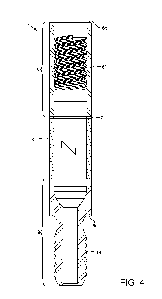
Figure 4 illustrates a drill rod having a second male coupling and a second
female
coupling, each coupling including a second wear resistant screw thread,
according to
another embodiment of the present disclosure;
Figure 5 illustrates the second male and female couplings screwed together;
RECTIFIED SHEET (RULE 91) ISA/EP
CA 03091534 2020-08-18
WO 2019/170437
PCT/EP2019/054455
-6-
Figure 6A illustrates male and female thread-forms of the second couplings
screwed
together in a new condition. Figure 6B illustrates the male and female thread-
forms in a
worn condition.
Detailed description
Figures lA and 1B illustrate a male coupling 1 and a female coupling 2 for a
percussion
drill string, each coupling including a wear resistant screw thread it, 2t,
according to one
embodiment of the present disclosure. The percussion drill string may be
formed by
.. screwing together a plurality of drill rods (Figure 4) together along with
a percussion drill
bit 3 at one end and a shank adapter (not shown) at the other end. The drill
rods may be
screwed together using the male 1 and female couplings 2. The drill string may
be used for
percussion rock drilling with a top hammer (not shown) or downhole hammer (not
shown).
If a downhole hammer is used, the hammer may have each of the wear resistant
screw
threads it, 2t for assembly as part of the drill string.
The male coupling I may be attached, such as welded, to an intermediate rod
body so as to
form a longitudinal end of a drill rod. The female coupling 2 may be formed
integrally
with the percussion drill bit 3. The male coupling 1 may have a tubular body
with an outer
.. diameter upper portion for connection to a lower end of the rod body, a
reduced diameter
lower portion having the external male thread it formed in an outer surface
thereof, and a
shoulder is connecting the upper and lower portions. The male thread it may
start at a
first standoff distance from the shoulder is. The male thread it may end at a
second
standoff distance from a bottom thereof. A guide portion, such as a conical
surface, may
.. be formed in the outer surface of the lower portion of the male coupling 1
between the end
of the male thread it and the bottom thereof. The upper portion of the male
coupling 1
may have a plurality of wrench flats (not shown) formed in an outer surface
thereof The
male coupling 1 may have a flow bore formed therethrough. An outer diameter of
the
couplings 1, 2 may range between two and 16 centimeters.
The female coupling 2 may serve as the shank of the percussion drill bit 3.
The percussion
drill bit 3 may further include a head. The head may have an outermost end
defining a
RECTIFIED SHEET (RULE 91) ISA/EP
CA 03091534 2020-08-18
WO 2019/170437 PCT/EP2019/054455
-7-
cutting face. The cutting face may have a plurality of sockets (only one
shown) formed
therein for receiving crushers (not shown). Each crusher may be a pre-formed
insert
mounted into the respective socket by interference fit or brazing. Each cutter
may be made
from a cermet material, such as a cemented carbide. The sockets and cutters
may be
spaced about the cutting face.
Figure 2 illustrates the male 1 and female 2 couplings screwed together. The
female
coupling 2 may have a tubular body. The female coupling 2 may have the
internal female
thread 2t formed in an inner surface thereof adjacent to the flow bore
thereof. The flow
bore may be sized to receive the reduced diameter lower portion of the male
coupling 1.
The male coupling 1 may be screwed into the female coupling 2 until the
shoulder is abuts
a top 2p of the female coupling, thereby creating a metal-to-metal seal for
isolating the
flow bore and fastening the two members together. The female thread 2t may
start at a
first standoff distance from the top 2p. The female thread 2t may end at a
second standoff
distance from a bottom of the female coupling 2. The flow bore of the female
coupling 2
may be in fluid communication with flow ports formed through the head of the
drill bit.
Each of the male it and female 2t threads may be single threads.
Figure 3A illustrates a thread-form 4f of the female thread 2t. Figure 3B
illustrates a
thread-form 4m of the male thread it. Each thread-form 4m,f may start at point
XB and
may include a root Ai. Each root Ai may be a concave arc with a respective
radius Ri and
may extend to a respective second arc A2. Each second arc A2 may be concave,
have a
respective radius R2, and may extend from the respective first crest Ai to a
respective
contact flank El. Each root radius Ri may be greater than the respective
second radius R2,
such as at least fifty percent greater than the respective second radius. Each
second radius
R2 may be greater than five percent of the outer diameter of the male coupling
1. This dual
arc configuration may significantly stress in the root region of the
respective thread-form
4m, 4f. Each contact flank Ei may be a straight line inclined at a respective
first flank
angle a relative to a respective baseline BL. The baseline BL may be
longitudinal and be
located at a respective major diameter DJ or minor diameter DN of the
respective thread it,
2t. Each first flank angle a may range between 15 and 50 degrees. Each contact
flank Ei
CA 03091534 2020-08-18
WO 2019/170437 PCT/EP2019/054455
-8-
may extend from the respective second arc A2 to a respective third arc A3.
Each third arc
A3 may be convex and have a respective radius R3.
Each third arc A3 may extend from the respective contact flank Ei to a
respective crest A4.
Each crest A4 may have a respective first height Hi adjacent to the respective
third arc A3
and a respective second height H2 adjacent to a respective fifth arc As. Each
height Hi,H2
may be measured from the respective baseline BL. Each crest A4 may be inclined
from the
respective contact flank Ei to the respective non-contact flank E2 such that a
respective
apex XA of the respective thread-form 4m, 4f defining the respective major
diameter DJ or
minor diameter DN is located adjacent to the respective non-contact flank.
Each thread-
form 4m, 4f may have a respective peak line PL which may be longitudinal and
be located
at the respective major diameter DJ or minor diameter DN of the respective
thread it, 2t.
Each diameter DN, DJ of the respective thread it, 2t may be constant. Due to
the
inclination of each crest A4, the respective second height H2 may be greater
than the
respective first height Hi. Each inclination may be accomplished by the
respective crest
A4 being a convex arc with a respective radius R4. Each crest radius R4 may be
greater
than ten percent of the outer diameter of the male coupling 1. Each crest A4
may extend
from the respective third arc A3 to a respective fifth arc As. Each second
height H2 may be
5 to 20 percent greater than the respective first height Hi.
Alternatively, each crest A4 may be linearly inclined.
Each fifth arc As may be convex, may have a respective radius Rs, and may
extend from
the respective crest A4 to a respective non-contact flank E2. Each non-contact
flank E2 may
be a straight line inclined at a respective second flank angle 0 relative to
the respective
baseline BL. Each second flank angle 0 may be greater than the respective
first flank angle
a, such as 5 to 30 degrees greater than the respective first flank angle,
thereby resulting in
an respective asymmetric thread-form 4m, 4f. Each non-contact flank E2 may
extend from
the respective fifth arc As to a respective sixth arc A6. Each sixth arc A6
may extend from
the respective non-contact flank E2 to a respective end point XE. Each sixth
arc A6 may be
concave and have a respective radius R6. Each thread-form 4m, 4f may have a
respective
pitch P defined by a longitudinal distance between the respective start point
XB and the
CA 03091534 2020-08-18
WO 2019/170437
PCT/EP2019/054455
-9-
respective end point XE. Each pitch P may be greater than the outer diameter
of the male
coupling 1.
An area of the male thread-from 4m may be at least two percent greater or even
at least
five percent greater than an area of the female thread-form 4f. This
enlargement of the
male thread-form 4m may increase the service life of the drill rods since the
male thread-
form is usually determinative.
Figure 4 illustrates a drill rod 5 having a female coupling 6 and a male
coupling 9, each
coupling including a respective wear resistant screw thread 6t, 9t, according
to another
embodiment of the present disclosure. The drill rod 5 may be made from a metal
or alloy,
such as steel. The drill rod 5 may also be case hardened, such as by
carburization. Each
coupling 6, 9 may be attached, such as welded 7, to an intermediate rod body 8
so as to
form longitudinal ends of the drill rod 5. The drill rod 5 may have a flow
bore formed
therethrough. The drill rod 5 may have a length of 6 meters. An outer diameter
of the
couplings 6, 9 may range between five and 15 centimeters.
A drill string may be formed by screwing together a plurality of drill rods 5
together
(Figure 5) along with a drill bit at one end and a shank adapter at the other
end. The drill
bit and shank adapter may also have either of the wear resistant screw threads
6t, 9t. The
drill string may be used for percussion rock drilling with a top hammer (not
shown) or
downhole hammer (not shown). If a downhole hammer is used, the hammer may have
each of the wear resistant screw threads 6t, 9t for assembly as part of the
drill string.
Alternatively, the drill rod 5 may have a pair of male couplings 9 and a
sleeve (not shown)
having a pair of female couplings 6 may be used to connect a pair of drill
rods together.
Alternatively, the drill bit may be connected to the bottom drill rod using
the couplings 1,
2. Alternatively, each coupling 6, 9 may be formed integrally with the rod
body 8 instead
of welded thereto.
The male coupling 9 may have a tubular body with an outer diameter upper
portion for
connection to a lower end of the rod body 8, a reduced diameter lower portion
having the
CA 03091534 2020-08-18
WO 2019/170437 PCT/EP2019/054455
-10-
external male thread 9t formed in an outer surface thereof, and a shoulder 9s
connecting
the upper and lower portions. The male thread 9t may start at a first standoff
distance from
the shoulder 9s. The male thread 9t may end at a second standoff distance from
a bottom
thereof A guide portion, such as a conical surface, may be formed in the outer
surface of
the lower portion of the male coupling 9 between the end of the male thread 9t
and the
bottom thereof The upper portion of the male coupling 9 may have a plurality
of wrench
flats (not shown) formed in an outer surface thereof. The flow bore in the
upper portion
may include a nozzle and a portion of a throat. The throat may extend through
the
shoulder 4s and the lower portion.
Figure 5 illustrates the male 9 and female 6 couplings screwed together. The
female
coupling 6 may have a tubular body with a lower portion for connection to an
upper end of
the rod body 8. The female coupling 6 may have the internal female thread 6t
formed in an
inner surface thereof adjacent to the flow bore thereof. The flow bore may be
sized to
receive the reduced diameter lower portion of the male coupling 9 of another
drill rod. The
male coupling 9 may be screwed into the female coupling 6 until the shoulder
9s abuts a
top 6p of the female coupling, thereby creating a metal-to-metal seal for
isolating the flow
bore and fastening the two drill rods together. The female thread 6t may start
at a first
standoff distance from the top 6p. The female thread 6t may end at a second
standoff
distance from a bottom of the female coupling 6. The flow bore of the female
coupling 6
may include a diffuser located adjacent to a lower end of the female thread
6t. Each of the
female 6t and male 9t threads may be double threads.
Alternatively, each of the female 6t and male 9t threads may be a single
thread or triple
threads. Alternatively, the male coupling 9 may be connected to an upper end
of the rod
body 8 and the female coupling 6 may be connected to a lower end of the rod
body. In this
alternative, the nozzle of the male coupling 9 would be a diffuser and the
diffuser of the
female coupling 6 would be a nozzle. Alternatively, any of the threads it, 2t,
6t, 9t may be
used to connect non-tubular members of the drill string.
Figure 6A illustrates the male 10m and female 10f thread-forms of the second
couplings 6,
9 screwed together in a new condition. Each thread-form 10m, 10f of the
respective
CA 03091534 2020-08-18
WO 2019/170437
PCT/EP2019/054455
- 1 1 -
second couplings 6, 9 may be similar to the respective thread-forms 4m, 4f
including the
root, the crest, the contact flank, the non-contact flank, and the various
arcs connecting the
members. Each second thread-form 10m, 10f may include the inclined crest and
asymmetry of the respective thread-form 4m, 4f within the parameters discussed
above.
The pitch of each second thread-form 10m, 10f may be less than that of the
respective
thread-form 4m,f and the height of the apex of each second thread-form 10m,
10f may be
greater than that of the respective thread-form 4m, 4f.
Figure 6B illustrates the male 10m and female 10f thread-forms in a worn
condition. Due
.. to the inclined crests of each second thread-form 10m, 10f, the contact
flanks Ei may
become enlarged in response to wear of the second couplings 6, 9. Further,
pitting formed
in regions G adjacent to the contact flanks Ei may be removed as a result of
the wear. The
enlarged flanks may decrease contact pressure and, in conjunction with the
removed pits,
may decrease risk of failure.