Note : Les descriptions sont présentées dans la langue officielle dans laquelle elles ont été soumises.
CA 03094158 2020-09-16
WO 2019/183069 PCT/US2019/022939
1
CLOSURE ARTICLE WITH AUXILIARY FASTENER
BACKGROUND
[0001] Plastic closure articles commonly known as "clip tags" are well
known, as
described in U.S. Patent 4,026,413 to Britt and U.S. Patent 4,911,293 to
Holmes, for example.
Such a clip tag is commonly used to close a flexible container such as a
plastic bag. An open end
of the bag is typically gathered and then inserted through a slit on the tag,
so that the gathered
bag is frictionally held in a hole of the tag.
SUMMARY
[0002] In one aspect, an article is configured to close a first product
and attach to a
second product. The article includes a tag and a fastener. The tag has a
perimeter. The tag
includes an aperture and a first cut connecting the aperture and the
perimeter. The aperture and
first cut are configured to accept a portion of the first product. The
fastener is connected to the
tag at a joint, wherein the fastener is configured to attach to the second
product.
[0003] This summary is provided to introduce concepts in simplified form
that are further
described below in the Detailed Description. This summary is not intended to
identify key
features or essential features of the disclosed or claimed subject matter and
is not intended to
describe each disclosed embodiment or every implementation of the disclosed or
claimed subject
matter. Specifically, features disclosed herein with respect to one embodiment
may be equally
applicable to another. Further, this summary is not intended to be used as an
aid in determining
the scope of the claimed subject matter. Many other novel advantages,
features, and
relationships will become apparent as this description proceeds. The figures
and the description
that follow more particularly exemplify illustrative embodiments.
BRIEF DESCRIPTION OF THE DRAWINGS
[0004] The disclosed subject matter will be further explained with
reference to the
attached figures, wherein like structure or system elements are referred to by
like reference
numerals throughout the several views. It is contemplated that all
descriptions are applicable to
like and analogous structures throughout the several embodiments.
CA 03094158 2020-09-16
WO 2019/183069 PCT/US2019/022939
2
[0005] FIG. 1 is a perspective view of a first exemplary embodiment of a
closure article
with a tag and an auxiliary fastener.
[0006] FIG. 2 is a front view of the article of FIG. 1.
[0007] FIG. 3 is a cross-sectional view, taken along line 3-3 of FIG. 2.
[0008] FIG. 4 is a back view of a second exemplary embodiment of a
closure article.
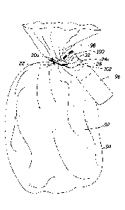
[0009] FIG. 5 is a cross sectional view, taken along line 5-5 of FIG. 4.
[0010] FIG. 6 is a back view of a third exemplary embodiment of a closure
article.
[0011] FIG. 7 is a cross sectional view, taken along line 7-7 of FIG. 6.
[0012] FIG. 8 shows a fourth exemplary embodiment of a closure article.
[0013] FIG. 9 shows a fifth exemplary embodiment of a closure article.
[0014] FIG. 10 shows a sixth exemplary embodiment of a closure article.
[0015] FIG. 11 is a partial cross-sectional view, taken along line 11-11
of FIG. 10.
[0016] FIG. 12 shows a first exemplary arrangement of a plurality of
closure articles.
[0017] FIG. 13 shows a second exemplary arrangement of a plurality of
closure articles.
[0018] FIG. 14 is a side cross-sectional view of a seventh exemplary
embodiment of a
closure article, taken along line 14-14 of FIG. 13.
[0019] FIG. 15 is a front view of an eighth exemplary embodiment of a
closure article.
[0020] FIG. 16 is a cross-sectional view taken along line 16-16 of FIG.
15.
[0021] FIG. 17 is a front view of a ninth exemplary embodiment of a
closure article.
[0022] FIG. 18 is a cross-sectional view taken along line 18-18 of FIG.
17.
[0023] FIG. 19 is a front view of a tenth exemplary embodiment of a
closure article.
[0024] FIG. 20 is a cross-sectional view taken along line 20-20 of FIG.
19.
[0025] FIG. 21 is a front view of an eleventh exemplary embodiment of a
closure article.
[0026] FIG. 22 is a side elevation view of the closure article of FIGS.
19 and 20 in a bent
configuration.
[0027] FIG. 23 is a partial front view of the closure article of FIGS.
19, 20 and 22 in the
bent configuration of FIG. 22.
[0028] FIG. 24 is a side elevation view, similar to that of FIG. 22, with
the closure article
expanded about a bundle of products.
[0029] FIG. 25 is a perspective view of the first exemplary embodiment of
a closure
article in use to close a first product bag and attach second product.
CA 03094158 2020-09-16
WO 2019/183069 PCT/US2019/022939
3
[0030] FIG. 26 is a perspective view of the fourth exemplary embodiment
of a closure
article in use to close a first product bag and attach second product.
[0031] FIG. 27 is a perspective view of the fifth exemplary embodiment of
a closure
article in use to close a first product bag and attach second product.
[0032] FIG. 28 is a perspective view of the sixth exemplary embodiment of
a closure
article in use to close a first product bag and attach second product.
[0033] FIG. 29 shows a third exemplary arrangement of a plurality of
closure articles, in
which each is a twelfth exemplary embodiment of a closure article.
[0034] FIG. 30 is a side view of the third arrangement, as viewed from
the right side of
FIG. 29.
[0035] FIG. 31 is a perspective view of the twelfth exemplary embodiment
of a closure
article, with the auxiliary fastener in a bent configuration.
[0036] FIG. 32 is a front view of the closure article of FIG. 31.
[0037] FIG. 33 is a top view of the closure article of FIG. 31.
[0038] FIG. 34 is a side view of the closure article of FIG. 31.
[0039] While the above-identified figures set forth one or more
embodiments of the
disclosed subject matter, other embodiments are also contemplated, as noted in
the disclosure. In
all cases, this disclosure presents the disclosed subject matter by way of
representation and not
limitation. It should be understood that numerous other modifications and
embodiments can be
devised by those skilled in the art that fall within the scope of the
principles of this disclosure.
[0040] The figures may not be drawn to scale. In particular, some
features may be
enlarged relative to other features for clarity. Moreover, where terms such as
above, below,
over, under, top, bottom, side, right, left, etc., are used, it is to be
understood that they are used
only for ease of understanding the description. It is contemplated that
structures may be oriented
otherwise.
DETAILED DESCRIPTION
[0041] The illustrations and written description depict and discuss
several embodiments
of closure articles having an auxiliary fastener. Components of the articles
are described and
shown with reference numbers. Such reference numbers, when used alone, refer
to the described
elements in general, such as with respect to one or more of the described
embodiments.
CA 03094158 2020-09-16
WO 2019/183069 PCT/US2019/022939
4
[0042] It is contemplated that many other changes in form and
configuration are possible
that fall within the scope of the present descriptions. In an exemplary
embodiment, closure
article 20 includes tag 22 and auxiliary fastener 24. As shown in FIGS. 1-7
and 25, auxiliary
fastener 24a, 24b, 24c is provided in the form of an elastomer loop. As shown
in FIGS. 8 and 26,
auxiliary fastener 24d is provided in the form of a twist tie article. As
shown in FIGS. 9-14, 27
and 28, auxiliary fastener 24e, 24f is provided in the form of a tin tie
article. As shown in FIGS.
15 and 16, auxiliary fastener 24g is provided in the form of an elastomer
sheet having a curved
cut. As shown in FIGS. 17 and 18, auxiliary fastener 24h is provided in the
form of an elastomer
band. As shown in FIGS. 19-24, auxiliary fastener 24i, 24j is provided in the
form of an
elastomer strap having a tab. However, in other embodiments, the auxiliary
fastener will take
other forms, being made in some cases of other materials in different
configurations than that
shown in the illustrated embodiments.
[0043] Typically, the closure articles 20 described in this disclosure
include the provision
of a tag 22 having a form and function similar to known clip tags. In an
exemplary embodiment,
tag 22 is formed of a polymer sheet having a perimeter and includes a cut or
slit 50 connecting
the perimeter and an aperture 52. Many configurations of tag 22 and
specifically of aperture 52
can be used. Articles 20 also provide an auxiliary fastener 24 that can be
used for attachment to
the same product that is attached to tag 22 or may be used to attach, bundle,
or otherwise connect
a second product to closure article 20.
[0044] As shown in FIGS. 1-3, closure article 20a is formed in an
exemplary
embodiment by cohesion of the materials for tag 22 and auxiliary fastener 24a,
resulting in a
joint 26a at an interface of tag 22 and auxiliary fastener 24a. In the
illustrated embodiment, joint
26a is a butt joint, in which tag 22 and auxiliary fastener 24a meet at a
single, substantially
planar interface. In an exemplary embodiment, auxiliary fastener 24 is formed
from a flexible
elastic layer that extends away from the tag 22 and is configured with an
elastic fastening loop
28. The entire article 20 is sheet-like in the sense that tag 22 is formed as
a sheet of a flat nature
and auxiliary fastener 24 is also formed as a sheet of flat character
(although auxiliary fastener
24 in particular may be drapeable and floppy and thus not always displayed in
flat form). The
tag 22 and auxiliary fastener 24 are joined so that the sheet character of
each extends onto the
sheet character of the other, giving a total unitary sheet-like character to
the entire article 20.
CA 03094158 2020-09-16
WO 2019/183069 PCT/US2019/022939
[0045] The flexible elastic fastening loop 28 has an inner perimeter edge
30 that defines
the boundary of an aperture 32 through the loop 28. While aperture 32 is
illustrated as circular, it
is contemplated that an aperture through a fastening loop can have any of a
variety of closed
shapes, including regular and irregular polygons, rounded shapes, and holes
having outlines with
segments that are curved, straight, and combinations thereof. In the exemplary
embodiments,
aperture 32 is spaced from joint 26a.
[0046] Dispersion zone 34 is defined between aperture 32 and joint 26.
Its function is to
disperse at least some of the in-line tension forces created as a result of
the stretching of elastic
loop 28 to allow the passage therethrough of a portion of a product, as
discussed below. Those
tension forces are called "in-line" tension forces because they are in the
line of stretching of the
loop 28. Dissipation of such tension forces is desirable at least to some
extent so as to reduce (or
sometimes even substantially eliminate) the stress of that tension passing
into the joint 26. In an
exemplary embodiment, a length dimension of dispersion zone 34 between
aperture 32 and joint
26 is at least about 50 mils (1.27 mm) and is more typically about 1/8 inch
(125 mils or 3.18
mm) or greater.
[0047] In exemplary embodiments, lateral shoulders 36 are located on both
sides of neck
38 and assist in relieving or dissipating tensioning forces within a stretched
loop 28 from being
transmitted into the joint 26 at its lateral edges. Thus, a relatively weaker
unification between
the tag 22 and the auxiliary fastener 24 at the joint 26 is sufficient as
compared to that required in
a structure without neck 38 and shoulders 36. However, other embodiments of an
auxiliary
fastener 24 may not have a narrowed neck region 38 or lateral shoulders 26.
[0048] In an exemplary embodiment, article 20 has a width between side
edges 42, 44
between about 0.25 inch (6.35 mm) and about 1 inch (25.4 mm). In an exemplary
embodiment,
article 20 has a length (substantially orthogonal to its width) between about
1 inch (25.4 mm)
and about 6 inches (152.4 mm). In exemplary embodiments, a length of auxiliary
fastener 24
extending away from joint 26 is between about 0.5 inch (12.7 mm) and about 5
inches (127 mm).
[0049] FIGS. 4 and 5 depict a second exemplary embodiment of a closure
article 20b.
Closure article 20b is similar to closure article 20a, except that auxiliary
fastener 24b is attached
to tag 22 at a joint 26 formed by an overlap of the flexible elastic material
of auxiliary fastener
24b and the typically more rigid material of tag 22. Joint 26b is disposed at
the bonded,
coextensive overlap of the tag 22 and an elastic layer of auxiliary fastener
24b. In the illustrated
CA 03094158 2020-09-16
WO 2019/183069 PCT/US2019/022939
6
embodiments, bond zone 44 has a generally rectangular configuration, due to
the shapes of the
overlapping portions of tag 22 and auxiliary fastener 24b. However, it is
contemplated that such
overlapping portions may have any shape, including those formed with irregular
edges. The
length of bond zone 44 is generally about 3/16 (4.76 mm) or 1/4 inch (6.35 mm)
or even 3/8 inch
(9.53 mm), but is usually not over about 1/2 inch (12.7 mm). Tag 22 interfaces
auxiliary fastener
24b along joint 26b so that a sheet character of each of tag 22 and auxiliary
fastener 24b extends
onto the sheet character of the other, giving a total unitary sheet-like
character to the entire
article 20b.
[0050] FIGS. 6 and 7 show a third exemplary embodiment of a closure
article 20c. In this
embodiment, auxiliary fastener 24c is attached to tag 22 at bond zone 26c,
which includes
adhesive layer 46. Accordingly, auxiliary fastener 24c may be produced
separately from tag 22,
rather than requiring all components of closure article 20c be manufactured in
a single
processing run. In an exemplary embodiment, auxiliary fastener 24c includes a
backer sheet 48
bonded to an elastic sheet material, wherein the backer sheet 48 is a
substantially non-stretchable
or inextensible structural support layer, which facilitates enhanced bonding
of the adhesive layer
46 to auxiliary fastener 24c. In an embodiment where tags 22 and auxiliary
fastener 24c are
provided separately to a user, a release liner (not shown) may be provided
over adhesive layer 46
to mask adhesive layer 46 until its exposure is desired for attachment to tag
22.
[0051] FIG. 8 shows a fourth exemplary embodiment of closure article 20d.
In this
embodiment, auxiliary fastener 24d is provided in the form of a twist-tie
fastener. Such fasteners
are commonly known as including a retention wire 54 sandwiched between
elongated strips of
sheet material 56, which form wings around the retention wire 54. Auxiliary
fastener 24d can be
attached to tag 22 by an adhesive similar to adhesive layer 46 described
above. Alternatively,
auxiliary fastener 24d can be formed with tag 22 in an in-line web-based
process. While
auxiliary fastener 24d is illustrated as extending past side edge 42 of tag
22, it is contemplated
that auxiliary fastener 24d may be positioned otherwise on tag 22, such as
extending past side
edge 40 but not side edge 42, or extending past both side edges 40, 42, for
example.
[0052] FIGS. 9 and 10 show embodiments of closure articles 20e and 20f.
These articles
are similar in that an auxiliary fastener 24e, 24f is provided in the form of
a tin-tie fastener
having two spaced apart retention wires 54 embedded in a strip 56. Closure
articles 20e, 20f
differ in the placement of the tin-tie fastener 24e, 24f with respect to tag
22. As shown in FIG. 9,
CA 03094158 2020-09-16
WO 2019/183069 PCT/US2019/022939
7
auxiliary fastener 24e of closure article 20e is offset (i.e., asymmetrically
positioned) with
respect to tag 22 so that auxiliary fastener 24e extends past only one side
edge 42 of tag 22. In
contrast, as shown in FIG. 10, auxiliary fastener 24f of closure article 20f
is substantially
centered to extend about equidistantly away from both side edges 40, 42 of tag
22. As shown in
FIG. 11, in closure article 20f, and also applicable to closure article 20e,
an adhesive layer 46
may be used to adhere the closure article 24e, 24f to tag 22. Alternatively,
closure article 24e,
24f could be formed integrally with tag 22 in an in-line web-based process.
[0053] FIG. 12 is a front view of a first exemplary arrangement 58 of a
plurality of
rupturably connected closure articles 20f', 20f". Each of these closure
articles is similar to
closure article 20f of FIG. 10, except that the placement of auxiliary
fastener 24f on tag 22 is
slightly different. For example, in closure article 20f', auxiliary fastener
24f' is spaced from a
bottom edge 60 of tag 22 to allow for the nesting of the auxiliary fastener
24f' of an adjacent
closure article 20f". In the illustrated embodiment, adjacent tags 22 are
rupturably connected to
each other via joints 62, which form breakable bridges between adjacent tags
22. Thus, a
plurality of closure devices 20f', 20f" can be presented to a user in a
connected arrangement 58,
which may be provided in a flat or rolled spooled form. While only three such
closure devices
20f', 20f' 'are illustrated, it is to be understood that the arrangement 58
can include any number
of closure articles 20f', 20f" alternately arranged along a length parallel to
bottom edge 60.
Moreover, an arrangement may include another row of rupturably connected
closure articles
attached at bottom edge 60 of each of tags 22 and/or top edge 64 of tags 22.
[0054] FIG. 13 is a front view of a second exemplary arrangement 66 of a
plurality of
rupturably connected closure articles. As illustrated, each closure article
20f" is formed so that
auxiliary fastener 24f is connected to tag 22 at a butt joint 26f. As shown in
FIG. 14, butt joint
26f joins wing 57 of auxiliary fastener 24f and tag 22. To accommodate for the
extension of
auxiliary fasteners 24f beyond the side edges 40, 42 of tags 22, a cut out
portion 68 of tag
material is provided between adjacent tags 22. In an exemplary manufacturing
method, material
of this cut-out portion 68 is recycled in a subsequent process for forming
additional tags 22.
Arrangement 66 can be formed by cohesion of the material for tag 22 and
auxiliary fastener 24f,
with the cut out portions 68 removed thereafter.
[0055] FIGS. 15 and 16 illustrate another exemplary embodiment of a
closure article 20g.
In this embodiment, auxiliary fastener 24g is provided in the form of an
elastic sheet bonded to a
CA 03094158 2020-09-16
WO 2019/183069 PCT/US2019/022939
8
surface of tag 22 underlying at least a portion of aperture 52 (such as, for
example, across
coextensive zone 29). In an exemplary embodiment, joint 26g is located at the
mutually bonded
overlap of tag 22 and the elastic sheet of auxiliary fastener 24g. In the
front view of FIG. 15, a
portion of the auxiliary fastener 24g is visible through slit 50 and aperture
52 of tag 22. Auxiliary
fastener 24g includes a cut or slit 70 provided in the flexible elastic
material of auxiliary fastener
24g. In use, a gathered neck of a flexible container such as a bag (such as
neck 98 of bag 94,
shown in FIG. 25) would be inserted into slit 70, which is coincident with
slit 50 and aperture 52
of tag 22. Accordingly, closure article 20g provides a more secure attachment
of tag 22 on a
product bag than would be accomplished by the simple fictional engagement of
aperture 52 with
the bag. The elastic material of auxiliary fastener 24g directly engages the
bag along slit 70,
which deforms and grips the bag. In an exemplary embodiment, auxiliary
fastener 24g is
attached at joint 26g to at least a portion of tag 22 that includes aperture
52 (as at coextensive
zone 29). While a particular curvilinear embodiment of slit 70 is illustrated
(e.g. a hook-shaped
slit), it is contemplated that such an opening in auxiliary fastener 24g can
be provided in other
configurations, including not only slits of other configurations, but also
barbed configurations,
apertures and combinations thereof.
[0056] FIGS. 17 and 18 illustrate another exemplary embodiment of a
closure article 20h,
in which an auxiliary fastener 24h is attached to tag 22 at joint 26h (such as
at coextensive zone
26h); the elastic sheet of auxiliary fastener 24h underlies at least a portion
of aperture 52. In this
embodiment, the elastic sheet material of auxiliary fastener 24h underlies
only a portion of
aperture 52 of tag 22. Auxiliary fastener 24h thus effectively reduces the
size of aperture 52 and
provides an elastic biasing force on a bag portion inserted therein to more
securely hold tag 22 of
closure article 20h on the product bag. Auxiliary fastener 24 may also enhance
the secure
closure of the bag via its contact with the elastic auxiliary fastener 24h.
[0057] FIGS. 19, 20 and 22-24 illustrate another exemplary embodiment of
a closure
article 20i, in which an auxiliary fastener 24i is attached to tag 22 at bond
zone 44i. In the
illustrated exemplary embodiment, auxiliary fastener 24i includes an elastic
sheet 78 joined to
tab 80i at bond zone 82. As shown in FIGS. 19 and 21, closure articles 20i and
20j are
substantially similar except for the shape of tabs 80i, 80j, respectively.
Accordingly, descriptions
with respect to one of the closure articles 20i, 20j apply to both embodiments
unless otherwise
indicated. In exemplary embodiments, tabs 80i, 80j may be formed of a material
that is similar to
CA 03094158 2020-09-16
WO 2019/183069 PCT/US2019/022939
9
a material used for tag 22. In other embodiments, the material for tab 80i,
80j is different from
that used for tag 22, but is relatively stiffer than a material of elastic
layer 78.
[0058] As shown in FIGS. 22 and 23, in an exemplary use of closure
article 20i, elastic
layer 78 is bent so that head 86i of tab 80i is twisted and inserted, via slit
50, into aperture 52 of
tag 22. In an exemplary embodiment, tab 80i is formed with a relatively narrow
neck 84 and a
larger dimensioned head 86i. The narrow neck 84 facilitates insertion through
slit 50, while the
larger dimensioned head 86i prevents unintentional removal of head 86i from
aperture 52 or slot
50. Thus, in an exemplary use, insertion of tab 80i into aperture 52 results
in a bent configuration
of closure article 20i that can be maintained despite tension placed by
articles inserted within
loop 88.
[0059] FIG. 23 shows a partial front view of closure article 20i in the
looped
configuration of FIG. 22. To enhance the engagement of tab 80 within tag 22,
other
configurations of tab 80 can be devised, such as the configuration illustrated
in FIG. 21 for tab
80j, for example. In the illustrated configuration, tab 80j includes neck 84
and a head 86j
including opposed barbs 92 extending from head 86j beyond neck 84. In a bent
configuration of
closure article 20j, similar to that shown for closure article 20i in FIG. 22,
barbs 92 facilitate
engagement and retention of head 86j at aperture 52 of tag 22.
[0060] As shown in FIG. 24, closure article 20i is shown with elastic
layer 78 in a
stretched or extended state about a bundle of a plurality of products 90. The
compressive force of
the elastic layer 78, as stretched about the products 90, helps to maintain
even irregularly shaped
product articles, such as broccoli stems, in a bundle. Moreover, as shown in
FIGS. 19-21 and 23,
indicia 72 may be provided on any or all of tag 22, elastic layer 78, or tab
80.
[0061] FIG. 25 is a perspective view of closure article 20a used with a
first product 92 to
close a bag 94 containing the first product 92 and to attach a second product
96. It is
contemplated that closure articles 20b and 20c may be used similarly and in
other manners as
desired to connect at least two products or bundled articles. As illustrated,
first product 92 is a
loaf of bread and second product 96 is a bottle of olive oil. It is
contemplated that any of a
variety of complementary or otherwise related products can be attached to each
other. For
example, the second product may be a sample offered by the same manufacturer
as the first
product. As shown in FIG. 25, the first product 92 is contained within a
flexible bag 94. To close
the bag 94, a user or machine cinches the bag 94 at a neck 98 and inserts the
gathered neck 98 of
CA 03094158 2020-09-16
WO 2019/183069 PCT/US2019/022939
the bag 94 into aperture 52 of tag 22 via slit 50. A user or machine inserts a
portion of second
product 96, such as cap 100 through aperture 32 of loop 28. In an exemplary
embodiment, loop
28 is dimensioned to stretch around cap 100 to allow its passage through
aperture 32 and then
conform to a relatively smaller dimension of neck 102 of second product 96 so
that compressive
forces of the elastic material of auxiliary fastener 24a maintains the
attachment of second product
96 to bag 94 and therefore to first product 92.
[0062] In an exemplary embodiment, retention wire 54 has dead fold
properties, by
which each of the auxiliary fasteners 24d, 24e, 24f can be maintained in a
bent or twisted
configuration. It is contemplated that auxiliary fastener 24d, 24e, 24f could
be bent or twisted
around a second product or a bundle of second products for attachment to tag
22 and its attached
first product.
[0063] FIG. 26 is a perspective view of closure article 20d in use with
first product 104
(contained in first bag 94) and second product 106 contained in second bag
108. In the illustrated
embodiment, each of first product 104 and second product 106 is a collection
of a plurality of
pieces. In the one example, first product 104 is a collection of candies and
second product 106 is
a collection of jelly beans. However, products 90, 92, 104 and 106 may be any
items of any
configuration.
[0064] In the illustrated embodiment, the second bag 108 containing the
second product
106 is attached to first product 104 via closure article 20d. As shown,
closure strip 56 is provided
in the form of a twist tie article. Closure strip 56 including retention wire
54 is tightened and
twisted about itself around the gathered neck 110 of bag 108. Thus, closure
article 20d
simultaneously closes bag 108 and attaches the bag 108 to the first bag 94,
which is closed by the
insertion of its neck 98 in a gathered configuration in aperture 50 of tag 22.
[0065] FIG. 27 is a perspective view of closure article 20e in use with
first product 104
(contained in first bag 94) and second product 106 contained in second bag
108. In the illustrated
embodiment, the second bag 108 containing the second product 106 is attached
to first product
104 via closure article 20e. As shown, closure strip 56 is provided in the
form of a tin tie article,
including two parallel retention wires 54. As illustrated, an end of closure
strip 56 is rolled or
folded around the gathered neck 110 of bag 108. Thus, closure article 20e
simultaneously closes
bag 108 and attaches the bag 108 to the first bag 94, which is closed by the
insertion of its neck
98 in a gathered configuration in aperture 50 of tag 22.
CA 03094158 2020-09-16
WO 2019/183069 PCT/US2019/022939
11
[0066] FIG. 28 is a perspective view of closure article 20f in use with
first product 104
(contained in first bag 94) and second product 106 contained in second bag
108. In the illustrated
embodiment, the second bag 108 containing the second product 106 is attached
to first product
104 via closure article 20f. As shown, closure strip 56 is provided in the
form of a tin tie article,
including two parallel retention wires 54. As illustrated, two opposite ends
of closure strip 56
are rolled or folded around the gathered neck 110 of bag 108. Thus, closure
article 20f
simultaneously closes bag 108 and attaches the bag 108 to the first bag 94,
which is closed by the
insertion of its neck 98 in a gathered configuration in aperture 50 of tag 22.
[0067] While the illustrations show that a product in a larger bag is
closed with tag 22
and a smaller product is attached with the auxiliary fastener 24, it is
contemplated that two
mutually connected products may be about the same size or that the product
attached to the
auxiliary fastener 24 may be larger than the product attached to tag 22.
Moreover, in FIGS. 26-
28, while strip 56 is illustrated as being fastened about the neck of a bag,
it is contemplated that
the strip 56 can be attached to other portions of products such as bottle
necks and other parts of
products having different configurations. In one example, if a second product
or its packaging
has a hanging aperture, strap or loop, the strip 56 can be inserted into or
about the hanging
structure to connect the second product to a first product attached to tag 22.
Other methods of use
can be devised, depending on product and packaging configurations.
[0068] In exemplary embodiments, tags 22 are formed of a stiffly
resilient sheet plastic
material that allows for deformation in use for ease of insertion of a portion
of a bag into aperture
52 and removal of the portion of the bag therefrom. As described, the present
disclosure
describes a closure article with an auxiliary fastener that can be used in
multiple manners to close
a product container such a flexible bag, attach a second product to the first
product and/or bundle
a plurality of products.
[0069] Rectangular style tags 22 are especially practical for economy
purposes, but tags
may take different forms such as octagonal shapes, triangular shapes,
rhomboidal shapes,
circular shapes, oval shapes, and irregular shapes. The tag material should be
flexible and
pliable but is preferably not elastic, and is therefore dimensionally stable,
for most applications.
In some embodiments, indicia 72 are provided on front surface 74 and/or back
surface 76 of tag
22. Such indicia 72 may be printed, embossed, or otherwise provided. In
exemplary
embodiments, indicia 72 are sufficiently water resistant to avoid
disintegration or destruction
CA 03094158 2020-09-16
WO 2019/183069 PCT/US2019/022939
12
when repeatedly subjected to water and washing operations (as is common for
produce displays
in supermarkets). The sheet material for the tag 22 also should be somewhat
tough in the sense
of being sufficiently tear resistant to deter damage to it during storage,
transport and display, or
by staff or customer handling.
[0070] Especially suitable materials for forming the tag 22 and/or tab 80
include woven
or non-woven fabrics, woven or non-woven films, paper, polymers, polystyrenic
thermoplastics,
polyolefinic thermoplastics, polyesters, and others that exhibit the
properties discussed (which
can vary depending on how the article is to be use). Suitable materials
include thermoplastic
materials and polymers of styrene, ethylene, propylene, as well as a variety
of other monomers
and mixtures of monomers (e.g., to make co-polymers and ter-polymers, etc.).
Suitable materials
also include PLA (poly lactic acid) resin materials. Any of a variety of
commercially available
inks compatible with, or accepted on, a tag sheet and retained thereon, and in
any desired color,
may be used to print indicia 72 on tag 22 if desired. Moreover, if it should
be desired to use
water-soluble ink markings, a thin film of water-insoluble plastic may be
applied over the ink to
enhance water resistance.
[0071] Exemplary materials for forming the elastic layer for auxiliary
fastener 24a, 24b,
24c, 24g, 24h, 24i, 24j are rubber-like in character in that they can bounce
back from a stretched
condition relatively quickly, but absolutely instantaneous retraction or
bounce back to an original
relaxed condition after stretching is not always critical for functional
elastic performance. A
variety of elastomers giving satisfactory elasticity and stretchability
include thermoplastic
elastomers that are at least heat softenable and even heat meltable to a
flowable or moldable
state. One of the more common families of thermoplastic elastomers include
styrenic block co-
polymers. This family includes styrene-butadiene styrene and styrene-ethylene-
butylene styrene.
Another family of useful thermoplastic elastomers include olefinic elastomers,
especially those
based on ethylene and polypropylene (e.g., where interposed different monomer
blocks are not
used but blocks of different tacticity -- atactic and isotactic -- are created
by using metallocene
catalysis polymerization). Yet another family of thermoplastic elastomers
include polyvinyl
chloride-based elastomers. Still other families of thermoplastic elastomers
can be based on
urethanes, nylon, and silicon, for example.
[0072] Selection of an elastomer material may take into account factors
such as cost and
bonding compatibility with a material of tag 22. Auxiliary fastener 24 is
bonded to tag 22 at
CA 03094158 2020-09-16
WO 2019/183069 PCT/US2019/022939
13
their mutual joint 26 using any suitable bonding technique, such as heat
sealing, adhesive
application, and the like. By "bonded," it is meant that the Auxiliary
fastener 24 and tag 22 are
cohered together so that they are integrated as parts of a single unit (e.g.,
closure article 20) and
do not mutually separate in use. Exemplary use applications are illustrated in
FIGS. 24-28.
Auxiliary fastener 24 and tag 22 remain connected to each other despite
tension forces placed on
joint 26 by the weight of attached products.
[0073] Generally, similar materials tend to bond together (as by polymer
bonding) better
than dissimilar materials; and materials of like polarity usually bond better
than materials of
unlike polarity. Thus, tag material selection can be made from polymers in the
same family as
the elastomer, such as those including at least some monomers related to, or
the same as those
present in, the elastomer chosen for the elastic layer of auxiliary fastener
24a, 24b, 24c, 24g, 24h,
24i, 24j. Surface treatments such as corona treatments also help to improve
bonding. Still
further, compatibilizers that adjust the polarity of material can be used to
improve bonding.
Additional information is described in U.S. Patent No. 8,635,795 to Ludlow et
al.; U.S. Patent
No. 9,105,205 to Ludlow et al.; and U.S. Patent Application Publication No.
2015/0239615 to
O'Donnell, et al., all of which are hereby incorporated by reference. A common
practice in
handling polymeric materials for tag 22 and an elastic layer for auxiliary
fastener 24a, 24b, 24c,
24g, 24h, 24i, 24j is to add compatible (i.e., readily blendable) ingredients
to achieve desired
properties such as coloration, opacification, resistance to degradation on
exposure to
environmental conditions, improved impact properties and adhesion properties,
for example.
[0074] Heat welding as by applying heat and pressure on overlapping
thermoplastic
polymeric materials forming the tag 22 and the elastic substrate of auxiliary
fastener 24a, 24b,
24c, 24g, 24h, 24i, 24j can be useful to form the bond therebetween at joint
26. Sonic welding is
another way to unify the layers and achieve a cohesive bond between compatible
parts. Bonds
can also be formed by interposing an intermediate layer at the joint 26 (e.g.,
a hot melt bonding
adhesive) to which both the tag material and the elastic layer material will
readily bond because
of their compatibility to the intermediate material. Still further, treatment
of the surface areas
where bonding is to be accomplished can be effective. Even mechanical bonding
can be
effective, as where the tag material is porous (e.g., paper and the porous
polymer product called
"Teslin"), and the elastomeric layer is applied in molten condition or at
least in a softened
condition and pressed into the voids or interstices of the porous tag layer.
Any useful bonding
CA 03094158 2020-09-16
WO 2019/183069 PCT/US2019/022939
14
technique and structure that joins the tag 22 with the elastic layer of
auxiliary fastener 24a, 24b,
24c, 24g, 24h, 24i, 24j in a manner forming a unifying flat joint 26 that can
withstand
delamination in expected use is suitable.
[0075] Those skilled in the art will recognize that any suitable process
for the
manufacture of closure articles 20 of the disclosure can be employed. Batch
processing is useful
for limited production runs. Conveyor processing with indexing from station to
station for
specific operations can be useful, especially for uniquely designed or shaped
tags or elastic or tie
substrates.
[0076] Web-based processing is especially suitable from the standpoint of
economy. For
example, for closure article 20b, a high impact polystyrene web is fed
simultaneously with
molten elastomer (e.g., a thermoplastic elastomer such as styrenic block
copolymer) through the
nip of chill rollers. The molten elastomer is applied to extend with a
sufficient overlap onto the
lateral edges of the web to create bond zone 44 as well as to extend
sufficiently laterally outward
from the bond zone (i.e, lateral edge of web) to provide material for
dispersion zone 34 and
elastic loop 28. The temperature of the chill rollers is adjusted to cool the
molten elastomer to an
at least partially cured state while simultaneously applying pressure (up to
about 500 psi) to form
the elastomer layer of auxiliary fastener 24b at the desired thickness and
also to bond tag 22 to
the elastomer layer of auxiliary fastener 24b at bond zone 44. Lateral and
longitudinal
positioning of the composite web (of tag and elastomer) is controlled as it is
passed in proper
registration between die cutting and anvil rollers to cut and score individual
article profiles that
are then severed into individual closure articles 20b.
[0077] FIGS. 29 and 30 show a third exemplary arrangement 112 of a
plurality of closure
articles 20k. In the illustrated embodiment, adjacent tags 22k are rupturably
connected to each
other via joints 62, which form breakable bridges between adjacent tags 22k.
Thus, a plurality of
closure devices 20k can be presented to a user in a connected arrangement 112,
which may be
provided in a flat or rolled spooled form. While only two closure articles 20k
are depicted, it is to
be understood that arrangement 112 may include any number of closure articles
20k similarly
connected in a strip at breakable joints 62. In an exemplary embodiment, tag
22k includes side
notches 114 to form a narrowed neck 116. In an exemplary embodiment, auxiliary
fastener 24k
in the form of strip 56 with retention wires 54 is centered on neck 116.
However, it is
CA 03094158 2020-09-16
WO 2019/183069 PCT/US2019/022939
contemplated that auxiliary fastener 24 of other configurations can be used,
such as an
elastomeric element or a strip with a single retention wire, for example.
[0078] FIGS. 31, 32, 33 and 34 are perspective, front, top and side
views, respectively, of
a single closure article 20k of arrangement 112, with the auxiliary fastener
24k in a bent
configuration. Such a bent configuration of auxiliary fastener 24k could be
useful for wrapping
around a portion of a product, for example. Though one configuration is shown,
it is
contemplated that auxiliary fastener 24k may be bent, rolled, twisted, or
otherwise configured.
As illustrated, because auxiliary fastener 24k bends around notches 114 of tag
22k, the notches
114 serve to offer a mechanical attachment means for auxiliary fastener 24k to
tag 22k, rather
than relying solely on an adhesive or other bonding of auxiliary fastener 24k
to tag 22k at joint
26.
[0079] Although the subject of this disclosure has been described with
reference to
several embodiments, workers skilled in the art will recognize that changes
may be made in form
and detail without departing from the scope of the disclosure. In addition,
any feature disclosed
with respect to one embodiment may be incorporated in another embodiment, and
vice-versa.