Note : Les descriptions sont présentées dans la langue officielle dans laquelle elles ont été soumises.
CA 03095798 2020-10-01
Laparoscope-Holding Robot System for Laparoscopic Surgery
Cross-reference to Related Application
The present disclosure claims the priority to the Chinese patent application
CN201810345131.1 filed on April 17, 2018 and entitled "Laparoscope-holding
Robot
System for Laparoscopic Surgery", and the priority to the Chinese patent
application
CN201810343711.7 filed on April 17, 2018 and entitled "Laparoscope-holding
Robot
System for Laparoscopic Surgery", the contents of the two applications above
are
incorporated herein by reference in entirety.
Technical Field
The present disclosure relates to the technical field of robot control, in
particular to a
laparoscope-holding robot system for laparoscopic surgery.
Background Art
Minimally invasive surgery has many advantages, such as rapid postoperative
recovery and small trauma, on the basis of conventional surgeries, and is
practiced and
rapidly developed. As a representative of minimally invasive surgery, the
laparoscopic
minimally invasive surgery has become a significant revolution for
conventional open
operations. With the extension of the minimally invasive surgical field, the
minimally
invasive surgical robot system provides a new approach for further perfecting
the
minimally invasive surgery against the limitations of conventional
laparoscopic
technology in clinical applications.
A common laparoscope-holding robot for laparoscopic surgery has certain
shortcomings in operation space and movement mode, and the endoscope position
also
needs to be adjusted by a doctor through manual operation, in particular, the
accuracy of
execution of complex actions is not high enough, and a relatively ideal degree
of
automation and intelligence cannot be achieved.
1
Date Recue/Date Received 2020-10-01
CA 03095798 2020-10-01
Summary
The present disclosure provides a laparoscope-holding robot system for
laparoscopic
surgery, for solving the technical problem in the prior art that the
laparoscope-holding
robot for laparoscopic surgery is inflexible in operation and also requires a
doctor to
assist in operation.
The present disclosure provides a laparoscope-holding robot system for
laparoscopic
surgery, including a trolley rack, a surgical tool and a mechanical arm
provided on the
trolley rack, wherein the surgical tool is fixed to a front end of the
mechanical arm,
wherein the mechanical arm has at least six degrees of freedom.
In one embodiment, the mechanical arm includes a terminal joint and an
intermediate
joint respectively connected to a first connecting arm and a second connecting
arm, and
the terminal joint includes a first joint connected to the trolley rack and a
sixth joint
connected to a mounting seat of the surgical tool.
In one embodiment, the intermediate joint includes a second joint rotationally
connected to the first joint, a third joint connecting the first connecting
arm and the
second connecting arm, a fourth joint rotationally connected to the second
connecting
arm and a fifth joint rotationally connected to the fourth joint and the sixth
joint,
respectively.
In one embodiment, when the second connecting arm rotates with an axis of the
third
joint as a rotation axis, a maximum rotation angle is 360 .
In one embodiment, when the first connecting arm rotates with an axis of the
second
joint as a rotation axis, a maximum rotation angle is 180 .
In one embodiment, the trolley rack includes a base and a post fixedly
provided on the
base, and the mechanical arm is provided on the post.
In one embodiment, an adapter flange is provided on a side surface of the
post, and
the mechanical arm is fixedly connected to the adapter flange.
In one embodiment, a top end of the post is provided with a mechanical
interface, and
the mechanical arm is fixedly connected to the mechanical interface.
2
Date Recue/Date Received 2020-10-01
CA 03095798 2020-10-01
In one embodiment, a wire pipe is provided on the first joint at a position
connected to
the trolley rack, and an axial direction of the wire pipe is perpendicular to
an axial
direction of the first joint and a height direction of the post, respectively.
In one embodiment, the bottom of the base is provided with two directional
casters
and two universal casters having a braking function, respectively.
The present disclosure further provides a laparoscope-holding robot system for
laparoscopic surgery, including a trolley rack, a surgical tool and a
mechanical arm
provided on the trolley rack, wherein a front end of the mechanical arm is
provided with
an extension plate having a quick-release device, and the surgical tool is
fixed on the
extension plate by the quick-release device, wherein the mechanical arm has at
least six
degrees of freedom.
In one embodiment, the mechanical arm includes a terminal joint and an
intermediate
joint respectively connected to a first connecting arm and a second connecting
arm, and
the terminal joint includes a first joint connected to the trolley rack and a
sixth joint
connected to a mounting seat of the surgical tool.
In one embodiment, the intermediate joint includes a second joint rotationally
connected to the first joint, a third joint connecting the first connecting
arm and the
second connecting arm, a fourth joint rotationally connected to the second
connecting
arm and a fifth joint rotationally connected to the fourth joint and the sixth
joint,
.. respectively.
In one embodiment, a rotation axis of the first joint is parallel to a height
direction of
the trolley rack, and perpendicular to the rotation axis of the second joint.
In one embodiment, a rotation axis of the fourth joint, a rotation axis of the
fifth joint
and a rotation axis of the sixth joint are perpendicular to each other.
In one embodiment, the trolley rack includes a base and a post fixedly
provided on the
base, and the mechanical arm is provided on the post.
In one embodiment, an adapter flange is provided on a side surface of the
post, and
the mechanical arm is fixedly connected to the adapter flange.
3
Date Recue/Date Received 2020-10-01
CA 03095798 2020-10-01
In one embodiment, a top end of the post is provided with a mechanical
interface, and
the mechanical arm is fixedly connected to the mechanical interface.
In one embodiment, a wire pipe is provided on the first joint at a position
connected to
the trolley rack, and an axial direction of the wire pipe is perpendicular to
an axial
direction of the first joint and a height direction of the post, respectively.
In one embodiment, the bottom of the base is provided with two directional
casters
and two universal casters having a braking function, respectively.
Compared with the prior art, the advantages of the present disclosure lie in
that: as the
mechanical arm has at least six degrees of freedom, the mechanical arm can
completely
simulate the movement range of the human arm, and has the same flexibility as
the
human arm, so as to accurately position the lesion position which actually
needs to be
operated without requiring a doctor to assist in operation.
Brief Description of Drawings
The present disclosure will be described in more detail below on the basis of
.. embodiments and with reference to the accompanying drawings.
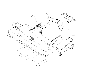
FIG. 1 is a schematic view of operation of a laparoscope-holding robot system
for
laparoscopic surgery in one embodiment of the present disclosure;
FIG. 2 is a schematic perspective structural view of the laparoscope-holding
robot
system for laparoscopic surgery in one embodiment of the present disclosure
(no
surgical tool is shown in the drawing);
FIG. 3 is a schematic structural view of a mechanical arm shown in FIG. 2;
FIG. 4 is a schematic view of a mechanical limit position of the mechanical
arm shown
in FIG. 1 (no surgical tool is shown in the drawing);
FIG. 5 is a schematic perspective structural view of a base shown in FIG. 1;
FIG. 6 is a schematic view of operation of the laparoscope-holding robot
system for
laparoscopic surgery in another embodiment of the present disclosure;
4
Date Recue/Date Received 2020-10-01
CA 03095798 2020-10-01
FIG. 7 is a schematic perspective structural view of the laparoscope-holding
robot
system for laparoscopic surgery in another embodiment of the present
disclosure (no
surgical tool is shown in the drawing);
FIG. 8 is a schematic perspective structural view of the base shown in FIG. 6;
FIG. 9 is a schematic perspective structural view of an extension plate shown
in FIG. 6;
and
FIG. 10 is an explosive view of an extension plate shown in FIG. 6.
Reference signs:
1-trolley rack; 2-surgical tool; 3-mechanical arm;
5-wire pipe; 6-adapter flange; 11-base;
12-post; 13-housing; 31-first joint;
32-second joint; 33-third joint; 34-fourth joint;
35-fifth joint; 36-sixth joint; 111-directional caster;
112-universal caster; 113-connecting plate.
Detailed Description of Embodiments
The present disclosure will be further described below in combination with the
accompanying drawings.
As shown in FIG. 1, the present disclosure provides a laparoscope-holding
robot
system for laparoscopic surgery, including a trolley rack 1, a surgical tool 2
and a
mechanical arm 3 provided on the trolley rack 1. In the laparoscopic surgery,
the surgical
tool 2 is an endoscope, and of course, the surgical tool 2 also may be other
instruments
required in minimally invasive surgeries.
The surgical tool 2 is fixed at a front end of the mechanical arm 3, wherein
the
mechanical arm 3 has at least six degrees of freedom. For example, the
mechanical arm
3 may have six degrees of freedom of rotation and more than one degree of
translational
freedom.
5
Date Recue/Date Received 2020-10-01
CA 03095798 2020-10-01
According to a first aspect of the present disclosure, the six degrees of
freedom of
rotation of the mechanical arm 3 are realized in a following manner.
The mechanical arm 3 includes a terminal joint and an intermediate joint
respectively
connected to a first connecting arm 37 and a second connecting arm 38, and the
terminal joint includes a first joint 31 connected to the trolley rack 1 and a
sixth joint 36
connected to a mounting seat 21 of the surgical tool 2.
Further, the intermediate joint includes a second joint 32 rotationally
connected to the
first joint 31, a third joint 33 connecting the first connecting arm 37 and
the second
connecting arm 38, a fourth joint 34 rotationally connected to the second
connecting arm
38 and a fifth joint 35 rotationally connected to the fourth joint 34 and the
sixth joint 36,
respectively. That is, two ends of the first connecting arm 37 are
respectively connected
to the second joint 32 and the third joint 33, and relative movement between
the first
connecting arm 37 and the second connecting arm 38 is realized by means of the
third
joint 33.
As shown in FIG. 2 (or FIG. 7), a rotation axis L1 of the first joint 31 is
parallel to a
height direction of the trolley rack 1, and perpendicular to a rotation axis
L2 of the
second joint 2. A rotation axis L4 of the fourth joint 34, a rotation axis L5
of the fifth joint
35 and a rotation axis L6 of the sixth joint 36 are perpendicular to each
other. Through
the rotation of the six joints above, the six degrees of freedom of rotation
of the
.. mechanical arm 3 can be realized, so that the action of the mechanical arm
3 can
completely simulate the movement of the human arm, so as to accurately
position the
lesion position which actually needs to be operated without requiring a doctor
to assist in
operation, so that the doctor's sight overlaps the lesion position that needs
to be
operated, avoiding increased operation risk caused by inconsistency of hands
and eyes
of the doctor.
Besides, each of the six joints above may be provided with a joint sensor, so
as to
measure an angle of rotation of each joint, thereby obtaining current posture
information
of the endoscope; moreover, all of the six joints above may be driven by a
motor.
Further, each of the above joints is an execution unit of action, and the
respective
execution units are connected in series, so that the respective joints have
relatively good
6
Date Recue/Date Received 2020-10-01
CA 03095798 2020-10-01
isotropy therebetween, without accumulated error, thus the whole machine of
robot is
enabled to have relatively high precision, and has the technical features such
as good
dynamic response.
When the second connecting arm 38 rotates with an axis of the third joint 33
as a
rotation axis, a maximum rotation angle is 360 0. As shown in FIG. 4, it shows
one
mechanical limit position of the second connecting arm 38.
When the first connecting arm 37 rotates with an axis of the second joint 32
as a
rotation axis, a maximum rotation angle is 180 .
In one embodiment of the present disclosure, the number of the above
mechanical
arms 3 may be two or more, the plurality of mechanical arms 3 may be fixed on
different
side portions of the trolley rack 1, and terminals of the mechanical arms 3
may be
mounted with different surgical tools 2, so as to satisfy requirements of
complex
surgeries.
As shown in FIG. 5 (or FIG. 8), the trolley rack 1 includes a base 11 and a
post 12
fixedly provided on the base 11, and the mechanical arm 3 is provided on the
post 12.
The base 11 and the post 12 are both provided inside the housing 13, and the
housing
13 not only integrate control components and mechanical components, but also
can give
a good appearance.
In the above, the base 11 is provided with a connecting plate 113, and the
connecting
plate 113 has one end fixedly connected to a bottom surface of the base 11,
and the
other end fixedly connected to the housing 13. Specifically, the connecting
plate 113 is
configured in an L shape, and a cable outlet is provided on the connecting
plate 113 at a
position connected to the housing. Besides, in order to enhance the strength
of the
connecting plate 113, reinforcing ribs are provided on the connecting plate
113.
In one embodiment of the present disclosure, the mechanical arm 3 is provided
on a
side surface of the post 12.
Optionally, an adapter flange 6 is provided on a side surface of the post 12,
and the
mechanical arm 3 is fixedly connected to the adapter flange 6. In the above,
the adapter
flange 6 is configured in an L shape, and has one end fixedly connected to a
side
7
Date Recue/Date Received 2020-10-01
CA 03095798 2020-10-01
surface of the post 12, and the other end fixedly connected to a bottom end of
the first
joint 31.
According to a second aspect of the present disclosure, one degree of
translational
freedom of the mechanical arm 3 is realized in a following manner.
The post 12 is provided with a sliding sleeve, and the mechanical arm 3 is
fixedly
connected to the sliding sleeve. The sliding sleeve can slide on the post 12,
so as to
realize one degree of translational freedom of the mechanical arm 3.
In one embodiment of the present disclosure, the mechanical arm 3 is provided
on a
top end of the post 12. In the above, the top end of the post 12 is provided
with a
mechanical interface, and the mechanical arm 3 is fixedly connected to the
mechanical
interface.
When the mechanical arm 3 is provided on the side surface of the post 12, and
an
upper end of the housing 13 is provided with an indicator light and/or a
control button, so
as to facilitate control over the mechanical arm 3.
Besides, the housing 13 further may be provided with a support plate, which
may be
used as a support platform, on the other side opposite to the mechanical arm
3.
As shown in FIG. 3, the first joint 31 is provided with a wire pipe 7 at a
position
connected to the trolley rack 1, and an axial direction of the wire pipe 7 is
perpendicular
to an axial direction of the first joint 31 and a height direction of the post
12, respectively.
Similarly, the six joint 36 is provided with a wire pipe at a position
connected to the
mounting base 21, so as to protect the wire led out from the joint.
The bottom of the base 11 is provided with two directional casters 111 and two
universal casters 112 having a braking function, respectively. Each universal
caster 112
may be provided with a brake device such as brake block, so as to realize the
function of
designated parking.
Besides, in order to facilitate operation, the directional casters 111 are
provided at a
front side of the post 12, and the universal casters 112 are provided at a
rear side of the
post 12.
8
Date Recue/Date Received 2020-10-01
CA 03095798 2020-10-01
In addition, it should be noted that an RCM point of the laparoscope-holding
robot
system for laparoscopic surgery in the present disclosure is ensured by the
algorithm of
control components.
In one embodiment of the present disclosure, the surgical tool 2 (i.e.,
endoscope) is
connected to the sixth joint 36 through the mounting base 21. In the above,
the mounting
base 21 is provided with a baseboard, the baseboard is provided with a quick-
release
device, and quick disassembling and mounting between the surgical tool and the
mechanical arm 3 can be realized by the quick-release device.
On the basis of the above embodiment, in another embodiment of the present
.. disclosure, as shown in FIG. 6, the present disclosure provides a
laparoscope-holding
robot system for laparoscopic surgery, including a trolley rack 1, a surgical
tool 2 and a
mechanical arm 3 provided on the trolley rack 1. A front end of the mechanical
arm 3 is
provided with an extension plate 4 having the quick-release device, and the
surgical tool
2 is fixed on the extension plate 4 by the quick-release device. A specific
fixing manner
will be described in detail below.
As shown in FIG. 10, a bottom end of the extension plate 4 is provided with a
mounting portion 47, the mounting portion 47 is provided on the mounting base
21, the
extension plate 4 has the quick-release device, and quick disassembling and
mounting
between the surgical tool and the mechanical arm 3 can be realized by the
quick-release
device.
Specifically, as shown in FIG. 9 and FIG. 10, the extension plate is provided
with an
upper connecting block 41 and a lower connecting block 42, the upper
connecting block
41 and the lower connecting block 42 are hinged, the upper connecting block 41
and the
lower connecting block 42 are each provided with a semicircular groove, and
when the
upper connecting block 41 and the lower connecting block 42 are put together,
the two
semicircular grooves form a mounting hole, the front end of the endoscope
extends into
the mounting hole, and a rear end of the endoscope is in contact with the
extension plate
4, so that two supporting points are formed on the extension plate 4, so as to
stably
support the endoscope.
9
Date Recue/Date Received 2020-10-01
CA 03095798 2020-10-01
When the endoscope is provided in the mounting hole, the upper connecting
block 41
and the lower connecting block 42 are locked by a first quick-release device,
i.e. a
locking pin shaft 43, so as to fix the endoscope in the mounting hole.
Specifically, the
locking pin shaft 43 can rotate in the upper connecting block 41 and the lower
connecting block 42, and be engaged with a boss on the bottom of the lower
connecting
block 42, to lock the upper connecting block 41 and the lower connecting block
42.
Besides, the lower connecting block 42 is provided with an adapter block 44 at
its
bottom, and the adapter block 44 and the extension plate 4 are fixed by a
second quick-
release device, i.e. an elastic fixture block. Specifically, the elastic
fixture block is
provided inside the extension plate 4, the extension plate 4 is provided with
a cover plate
46 at the bottom, and the elastic fixture block and the extension plate 4 can
generate
relative movement through a compression spring. An end of the elastic fixture
block is
inserted into the adapter block 44, and is snap-fitted with the adapter block
44, so that
the adapter block 44 is fixed on the extension plate 4. When disassembling is
needed,
the lock button 45 is pressed down, then the elastic fixture block moves
towards a
direction away from the adapter block 44, so that no snap-fit relationship is
generated
any more between the elastic fixture block and the adapter block 44, then the
adapter
block 44 can be taken away from the extension plate 4, thus achieving the
purpose of
quick disassembling.
Although the present disclosure has been described with reference to preferred
embodiments, various improvements can be made thereto and components therein
may
be replaced by equivalents, without departing from the scope of the present
disclosure.
In particular, various technical features mentioned in various embodiments may
be
combined in any manner as long as there is no structural conflict. The present
disclosure
is not restricted to specific embodiments disclosed herein, but covers all
technical
solutions falling within the scope of the claims.
Date Recue/Date Received 2020-10-01