Note : Les descriptions sont présentées dans la langue officielle dans laquelle elles ont été soumises.
CA 03096244 2020-10-05
PCT/NZ2019/050035
Received 05/02/2020
1
Remote Operated Vehicles and/or Autonomous Underwater Vehicles
FIELD
This invention relates to Remote Operated Vehicles and/or to Autonomous
Underwater Vehicles.
BACKGROUND
The present invention relates to remote operated vehicles or ROVs for use
underwater, and/or to autonomous underwater vehicles or AUVs.
ROVs typically comprise a "submarine" unit or vehicle (vehicle), a top-side
remote
control unit (topside unit), and an umbilical cable connecting the two units
together for transmitting control signals from the topside unit to the
vehicle, and
for transmitting information, video and signals from the vehicle to the
topside
unit. The umbilical cable may also transmit power for the vehicle or the
vehicle
may contain its own power source (batteries).
AUVs differ from ROVs in that they don't have an umbilical, always carry their
own
power source, and are instead programmed to accomplish a certain task on their
own using sensors and/or position information. AUVs may communicate without
a tether to the surface, but the amount of information that can be sent in
either
direction is limited.
ROV/AUV thrusters can disturb silt when operating near the bottom or within
submerged structures or wrecks. The silt can result in moderate to severe
visual
impairment and it can adversely affect measurements and sampling. The silt
disturbance is the result of thrust towards the bottom or silted surface or it
is the
result of turbulence or hydrodynamic effects of the vehicles motion. Avoiding
silt
disturbance is a common requirement of ROVs/AUVs working near silt.
AMENDED SHEET
IPE/k/ATur
CA 03096244 2020-10-05
PCT/NZ2019/050035
Received 05/02/2020
2
It is an object of the invention to provide a Remote Operated Vehicle or to at
least
provide the public or industry with a useful choice.
SUMMARY
According to one example embodiment there is provided an underwater vehicle
comprising:
a vehicle body, having a centre, a front, back, sides, top and bottom;
a plurality of thrusters aligned such that the thrusters are offset from the
vertical and horizontal relative to the centre of the vehicle, each of the
plurality of
thrusters being located at a corner of the vehicle, the offset of the
thrusters being
such that thrust from the thrusters is outside of an area defined by a front
frustoconical cone projecting from the front of the vehicle body and a rear
frustoconical cone projecting from the rear of the vehicle body, the front
frustoconical cone being centred on the centre of the front of the vehicle,
the front
frustoconical cone having a small end and a large end, the small end of the
front
frustoconical cone located at the front of the vehicle, the rear frustoconical
cone
being centred on the centre of the rear of the vehicle, the rear frustoconical
cone
having a small end and a large end, the small end of the rear frustoconical
cone
located at the rear of the vehicle; and
a controller operable to activate the thruster to move the vehicle in a
desired direction.
Preferably the vehicle further has a dome located at the front of the vehicle,
the
small end of the front frustoconical cone being substantially the size of as
the
dome.
Preferably a camera lens is located in the dome and substantially directed
horizontally to the front of the vehicle, the thrusters being located such
that the
AMENDED SHEET
IPE/k/ATur
CA 03096244 2020-10-05
PCT/NZ2019/050035
Received 05/02/2020
3
thrusters are located on the vehicle such that the thrusters are within a
vertical
plane at the front of the lens.
Alternatively the dome is replaced by a flat window.
Preferably the underwater vehicle has a centre of mass and a centre of
buoyancy
and the underwater vehicle is balanced such that the centre of mass and the
centre of buoyancy are the same.
Preferably the thrusters are offset between 40 and 50 degrees from vertical
and
horizontal.
More preferably the thrusters are offset between 44 and 46 degrees from
vertical
and horizontal.
Even more preferably the thrusters are offset 45 degrees from vertical and
horizontal.
Preferably the plurality of thrusters is 8 thrusters.
Preferably the controller is operable to move the vehicle with less than 8
thrusters.
Preferably controller is operable to detect inoperable thrusters.
Preferably the controller is operable to detect objects that may be disturbed
by
thruster operation and operate the thrusters to minimise disturbance.
Preferably the object that may be disturbed is silt.
Preferably the vehicle is remotely controlled.
Alternatively the vehicle is a Remote Operated Vehicle.
Alternatively the vehicle is autonomous.
AMENDED SHEET
IPE/k/ATur
CA 03096244 2020-10-05
PCT/NZ2019/050035
Received 05/02/2020
4
Alternatively the vehicle is an Autonomous Underwater Vehicle.
According to a further example embodiment there is provided an underwater
vehicle comprising:
a vehicle body, having a centre;
a plurality of thrusters aligned such that the thrusters are offset from the
vertical and horizontal relative to the centre of the vehicle, each of the
plurality of thrusters being located at a corner of the vehicle, the offset of
the thrusters being such that thrust from the thrusters is outside of an area
defined by a front frustoconical cone projecting from the front of the vehicle
body and a rear frustoconical cone projecting from the rear of the vehicle
body, the front frustoconical cone being centred on the centre of the front
of the vehicle, the front frustoconical cone having a small end and a large
end, the small end of the front frustoconical cone located at the front of the
vehicle, the rear frustoconical cone being centred on the centre of the rear
of the vehicle, the rear frustoconical cone having a small end and a large
end,
the small end of the rear frustoconical cone located at the rear of the
vehicle;
and
a controller operable to activate the plurality of thrusters to move the
vehicle in a desired direction, wherein the controller is operable to move the
vehicle with less than all the plurality of thrusters.
Preferably the controller is operable to detect inoperable thrusters.
Preferably the controller is operable to detect objects that may be disturbed
by
thruster operation and operate the thrusters to minimise disturbance.
Preferably the object that may be disturbed is silt.
Preferably the plurality of thrusters is 8 thrusters.
AMENDED SHEET
IPE/k/ATur
CA 03096244 2020-10-05
PCT/NZ2019/050035
Received 05/02/2020
Preferably wherein the vehicle is remotely controlled.
Alternatively the vehicle is a Remote Operated Vehicle.
Alternatively the vehicle is autonomous.
Alternatively the vehicle is an Autonomous Underwater Vehicle.
5 According to a yet further example embodiment there is provided an
underwater
vehicle comprising:
a vehicle body, having a centre;
a plurality of thrusters aligned such that the thrusters are offset from the
vertical and horizontal relative to the centre of the vehicle, each of the
plurality of thrusters being located at a corner of the vehicle, the offset of
the thrusters being such that thrust from the thrusters is outside of an area
defined by a front frustoconical cone projecting from the front of the vehicle
body and a rear frustoconical cone projecting from the rear of the vehicle
body, the front frustoconical cone being centred on the centre of the front
of the vehicle, the front frustoconical cone having a small end and a large
end, the small end of the front frustoconical cone located at the front of the
vehicle, the rear frustoconical cone being centred on the centre of the rear
of the vehicle, the rear frustoconical cone having a small end and a large
end,
the small end of the rear frustoconical cone located at the rear of the
vehicle;
and
a controller operable to activate the plurality of thrusters to move the
vehicle in a desired direction, wherein the controller is operable to detect
objects that may be disturbed by thruster operation and operate the
thrusters to minimise disturbance.
Preferably the object that may be disturbed is silt.
AMENDED SHEET
IPE/k/ATur
CA 03096244 2020-10-05
PCT/NZ2019/050035
Received 05/02/2020
6
Preferably the plurality of thrusters is 8 thrusters.
Preferably the vehicle is remotely controlled.
Alternatively the vehicle is a Remote Operated Vehicle.
Alternatively the vehicle is autonomous.
Alternatively the vehicle is an Autonomous Underwater Vehicle.
It is acknowledged that the terms "comprise", "comprises" and "comprising"
may,
under varying jurisdictions, be attributed with either an exclusive or an
inclusive
meaning. For the purpose of this specification, and unless otherwise noted,
these
terms are intended to have an inclusive meaning ¨ i.e., they will be taken to
mean
an inclusion of the listed components which the use directly references, and
possibly also of other non-specified components or elements.
Reference to any document in this specification does not constitute an
admission
that it is prior art, validly combinable with other documents or that it forms
part
of the common general knowledge.
BRIEF DESCRIPTION OF THE DRAWINGS
The accompanying drawings which are incorporated in and constitute part of the
specification, illustrate embodiments of the invention and, together with the
general description of the invention given above, and the detailed description
of
embodiments given below, serve to explain the principles of the invention, in
which:
Figure 1 is an isometric view of the vehicle of an example
embodiment;
Figure 2 is a view of an electronic topside unit of an example
embodiment;
Figure 3 is a front view of the vehicle of Figure 1;
AMENDED SHEET
IPE/k/ATur
CA 03096244 2020-10-05
PCT/NZ2019/050035
Received 05/02/2020
7
Figure 4 is an end view of the vehicle of Figure 1;
Figure 5 is a top view of the vehicle of Figure 1;
Figure 6 is a bottom view of the vehicle of Figure 1;
Figure 7 is a schematic diagram of one embodiment of a vehicle
showing the
thruster vectors;
Figure 8 is a schematic diagram of a further embodiment of a vehicle
showing the thruster vectors;
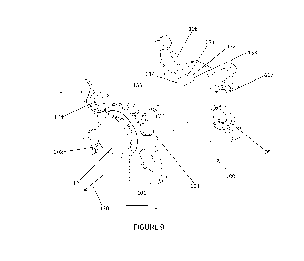
Figure 9 is an isometric view of the vehicle of Figure 1 showing a
frustoconical cone into which the thrusters do not direct any thrust;
Figure 10 is a top view of the vehicle of Figure 1 showing a frustoconical
cone
into which the thrusters do not direct any thrust;
Figure 11 a bottom view of the vehicle of Figure 1 showing a frustoconical
cone
into which the thrusters do not direct any thrust;
Figure 12 is a first side view of the vehicle of Figure 1 showing a
frustoconical
cone into which the thrusters do not direct any thrust; and
Figure 13 is a second side view of the vehicle of Figure 1 showing a
frustoconical cone into which the thrusters do not direct any thrust.
DETAILED DESCRIPTION
CONTROL
The vehicle 100 in one embodiment illustrated in Figures 1 and 3 to 6 contains
8
thrusters 101- 108 in the corners of an open rectangular design. The thrusters
101-108 are offset from the vertical and from the horizontal in the manner
shown
in Figure 1 and Figures 3 to 6. Preferably the offset is between 40 and 50
degrees
AMENDED SHEET
IPElk/ATur
CA 03096244 2020-10-05
PCT/NZ2019/050035
Received 05/02/2020
8
from vertical and horizontal. More preferably the offset is between 44 and 46
degrees from vertical and horizontal. Even more preferably the offset is 45
degrees from vertical and horizontal.
It should be noted that pitch control with this thruster configuration is
dependent
on the vehicle 100 having a length which differs reasonably from height.
The thrusters in this configuration allow independent control of the three
rotational axes (roll, pitch, and yaw), and the three translational axes being
x/Iongitudinal/surge; y/lateral/sway; and z/vertical/heave.
In use the vehicle 100 has a forward direction and a dome 121 is located at
the
front of the vehicle 100. The dome is typically transparent and can be
replaced
by a flat plate window. The vehicle 100 having a front, a back, sides, a top
and a
bottom. The dome 121 typically houses at least one camera having a lens 125.
The dome 121 may house more than one lens. The rear of the vehicle 100 may
also have a dome 122. Typically the dome 122 at the rear of the vehicle is
smaller
and may also house a camera.
Referring to Figures 7 and 8 two alignment options for the thrusters 101-108
are
illustrated. Referring to Figure 7 the vehicle 300 has 8 thrusters and a front
dome
321. The thrust angles are illustrated by arrows 301-308. The thrust angles
all
point away from the front dome and the rear. In a similar manner referring to
Figure 8 the vehicle 400 has 8 thrusters and a front dome 421. The thrust
angles
are illustrated by arrows 401-404 and 406-408. The thrust angles all point
away
from the front dome and the rear.
The thrusters 101-108 thus do not direct water in front of the dome. This can
be
seen in Figures 9 to 13 and which show a frustoconical cone 161 in dashed
lines
showing the area into which no thrust is directed. The frustoconical cone 161
being centred on the centre of the front of the vehicle 100 and having a
smaller
AMENDED SHEET
IPE/k/ATur
CA 03096244 2020-10-05
PCT/NZ2019/050035
Received 05/02/2020
9
end 162 and a larger end 163. The smaller end 162 of the frustoconical cone
161
being substantially the same diameter as the diameter of the dome. 121. This
allows the camera lens 125 in the dome 121 to be unobstructed. In a similar
manner a frustoconical cone area at the rear 122 of the vehicle 100 also has
no
thrust directed into it by the thrusters 101-108. The frustoconical cone being
centred on the centre of the front of the vehicle. The rear frustoconical cone
also
has the smaller end of the frustoconical cone being substantially the same
diameter as the diameter of the front dome 121.
The frustoconical cone angle in one embodiment being approximately 90 degrees
less the angle of the thrusters. For example if the thruster angle is 45
degrees the
cone angle is approximately 45 degrees, if the thruster angle is 50 degrees
the
cone angle is approximately 40 degrees. Other cone angles are also possible,
for
example the cone angle may relate to the angle of the lens.
This orientation of the thrust angles allows a camera with a fisheye lens to
be used
without the lens view being obstructed by the thrusters 101-108. Further
referring
to Figure 6 the thrusters 101-104 are located such that they are behind the
plane
of the lens 125. In a similar manner referring to Figure 6 the thrusters 105-
108 are
in front of the lens at the rear 122 of the vehicle.
A control system 135 uses orientation notation and magnitude to refer to the
thrust (of individual thrusters or the effect of combined output) which are
referred
to as thrust vectors below.
In an embodiment where the thrusters 101-108 used on the vehicle 100 have a
slight bias in maximum thrust output in the forward direction 120, the
thrusters
101-108 can be placed so that when the vehicle is moving forward the thrusters
are all driving forward to achieve maximum total thrust. This results in lower
maximum total thrust when moving laterally or vertically than forward.
AMENDED SHEET
IPE/k/ATur
CA 03096244 2020-10-05
PCT/NZ2019/050035
Received 05/02/2020
The vehicle 100 is preferably balanced such that the centre of mass and the
centre
of buoyancy are the same. This allows the vehicle 100 to expend the least
amount
of energy to hold an arbitrary position in the water. This is quite distinct
from the
vast majority of underwater vehicles which typically have the centre of
buoyancy
5 well above the centre of mass.
The vehicle 100 in an example embodiment contains an onboard 3-axis gyroscope
131 and 3-axis accelerometer 132. The sensor data from these two sensors
(which
may be combined into one device) are optionally fused using Kalman filters to
produce accurate and responsive roll, pitch, and yaw angles (Euler angles),
10 orientation quaternions, or any other orientation notation output and
representations of the rates of rotation (e.g. full quaternions for
orientation which
include rotation rate).
The vehicle 100 may contain an onboard 3-axis electronic compass 133 which may
optionally be fused with the gyroscope 131 output using a Kalman filter to
increase
the responsiveness of the compass. If the compass 133 is enabled, then it can
be
used instead of the yaw angle from the gyroscope to maintain a heading which
is
free from the drift present in gyroscope yaw data.
An electronic topside unit 201 sends commands to the vehicle 100 that indicate
the target Euler angles, orientation quaternions, or other orientation
notation.
These is referred to below as the Commanded Orientation.
A control system 135 is responsible for maintaining the attitude of the
vehicle 100
in the water both while stationary and moving.
The control system 135 uses control loop feedback mechanisms to maintain the
Commanded Orientation. The control loop may make use of both the orientation
and rate of change. The output of such feedback mechanisms is a vector which
AMENDED SHEET
IPE/k/ATur
CA 03096244 2020-10-05
PCT/NZ2019/050035
Received 05/02/2020
11
corresponds to the total thrust required to correct and maintain the Commanded
Orientation. We call this thrust vector the stabilisation thrust vector.
The topside unit 201 can also send commands to the vehicle 100 that indicate
the
target translational (x, y, z) thrust. If the vehicle is equipped with a means
or
determining the speed at which it is moving along any of the translational
axes or
its position along the axis with great accuracy, then the topside unit 201 may
send
commands to indicate the speed at which to move and/or the distance to move
along that axis.
A depth sensor 134 on the vehicle 100 allows the vertical (z) position (depth)
and
rate of change to be determined to great accuracy.
A Doppler velocity log may be used to determine speed and distance travelled
along the longitudinal and lateral (x and y) axes. Other speed sensors may
alternatively be used to measure speed along the longitudinal and lateral
axes.
For the translational axis where relative position data or rate of movement
data is
available (or can be reasonably calculated), the control system 135 may employ
control loop feedback mechanisms to maintain position, speed, depth or rate of
change.
The translational thrusts are placed in a thrust vector and added to which the
stabilisation thrust vector is added. The resulting thrust vector is the
target thrust
vector.
The control system 135 is configured with the position of each thruster 101-
108,
measured from the centre of mass, and the angles each thruster is offset from
the
longitudinal axis towards the lateral and vertical axes. This information is
used to
calculate the length of the lever arms and then using simple geometry to
calculate
the thrust vector that each individual thruster applies to the vehicle.
AMENDED SHEET
IPE/k/ATur
CA 03096244 2020-10-05
PCT/NZ2019/050035
Received 05/02/2020
12
While the individual thruster speeds can be calculated from the target thrust
vector using a linear algebra pseudoinverse, the solution, may only be locally
optimised and gimbal lock may result. In addition, there may be a high cost in
re-
calculating an optimal pseudoinverse when one or more thrusters fail.
The system instead converts the target thrust vector to a set of individual
thruster
101-108 speeds through an iterative method.
In order to reduce having to iterate through all possible forward and backward
speeds for each thruster 101-108, a process which could take an extremely long
time to complete, the problem is simplified by looking at only certain logical
groupings of thrusters 101-108.
Each grouping indicates whether each of the 8 thrusters 101-108 are to be run
(1)
forward, (-1) backward or not used (0), the thruster use status. Most of the
groupings are chosen so that they have particular goals, for instance running
all
thrusters forward will cause the vehicle to move forward without any lateral,
vertical or torque components. Other groupings using all 8 thrusters 101-108
allow for independent roll, pitch, yaw, lateral and vertical movements. In
addition,
there are groupings of 4 thrusters that can achieve the same independent
control.
And to this we add a small set of 4 thruster groupings which are not optimal ¨
for
example, they may largely cause the vehicle to roll, but will also cause some
other
(undesirable) movement. We also add all adjacent two thruster groups and all
individual thrusters.
In the Table 1 below thrusters are 101-108: bottom forward port, bottom
forward
starboard, top forward port, top forward starboard, bottom aft port, bottom
aft
starboard, top aft port, top aft starboard.
AMENDED SHEET
IPE/k/ATur
CA 03096244 2020-10-05
PCT/NZ2019/050035
Received 05/02/2020
13
Thruster Number
101 102 103 104 105 106 107 108 Description of resulting thrust vector *
1 1 1 1 1 1 1 1 all forward
-1 -1 -1 -1 -1 -1 -1 -1 all back
-1 -1 1 1 1 1 -1 -1 all up
1 1 -1 -1 -1 -1 1 1 all down
-1 1 -1 1 1 -1 1 -1 all port
1 -1 1 -1 -1 1 -1 1 all starboard
1 -1 -1 1 -1 1 1 -1 all roll ccw
-1 1 1 -1 1 -1 -1 1 all roll cw
1 1 -1 -1 1 1 -1 -1 all pitch down
-1 -1 1 1 -1 -1 1 1 all pitch up
-1 1 -1 1 -1 1 -1 1 all yaw port
1 -1 1 -1 1 -1 1 -1 all yaw starboard
1 1 1 1 0 0 0 0 front forward
-1 -1 -1 -1 0 0 0 0 front back
O 0 0 0 1 1 1 1 back forward
0 0 0 0 -1 -1 -1 -1 back back
O 0 1 1 0 0 -1 -1 top up
0 0 -1 -1 0 0 1 1 top down
-1 -1 0 0 1 1 0 0 bottom up
1 1 0 0 -1 -1 0 0 bottom down
-1 0 -1 0 1 0 1 0 port port
1 0 1 0 -1 0 -1 0 port starboard
O 1 0 1 0 -1 0 -1 starboard port
0 -1 0 -1 0 1 0 1 starboard starboard
1 0 0 1 -1 0 0 -1 odd roll ccw
-1 0 0 -1 1 0 0 1 odd roll cw
O -1 -1 0 0 1 1 0 even roll ccw
O 1 1 0 0 -1 -1 0 even roll cw
1 1 0 0 0 0 -1 -1 easy pitch down
-1 -1 0 0 0 0 1 1 hard pitch up
0 0 -1 -1 1 1 0 0 hard pitch down
O 0 1 1 -1 -1 0 0 easy pitch up
-1 0 -1 0 0 1 0 1 easy yaw port
1 0 1 0 0 -1 0 -1 hard yaw starboard
O 1 0 1 -1 0 -1 0 hard yaw port
O -1 0 -1 1 0 1 0 easy yaw starboard
1 1 0 0 0 0 1 1 alternate group forward (less ideal)
-1 -1 0 0 0 0 -1 -1 alternate group back (less
ideal)
0 0 1 1 1 1 0 0 alternate group forward (less ideal)
O 0 -1 -1 -1 -1 0 0 alternate group back (less
ideal)
-1 -1 0 0 0 0 -1 -1 alternate group up (less ideal)
1 1 0 0 0 0 1 1 alternate group down (less ideal)
O 0 1 1 1 1 0 0 alternate group up (less ideal)
O 0 -1 -1 -1 -1 0 0 alternate group down (less
ideal)
-1 0 -1 0 0 -1 0 -1 alternate group port (less
ideal)
1 0 1 0 0 1 0 1 alternate group starboard (less
ideal)
0 1 0 1 1 0 1 0 alternate group port (less ideal)
O -1 0 -1 -1 0 -1 0 alternate group starboard
(less ideal)
AMENDED SHEET
IPE/k/ATJ
CA 03096244 2020-10-05
PCT/NZ2019/050035
Received 05/02/2020
14
1 0 0 1 0 1 1 0 alternate group roll ccw (less ideal)
-1 0 0 -1 0 -1 -1 0 alternate group roll cw (less
ideal)
O -1 -1 0 -1 0 0 -1 alternate group roll ccw (less
ideal)
O 1 1 0 1 0 0 1 alternate group roll cw (less
ideal)
1 1 0 0 1 1 0 0 alternate group pitch down (less
ideal)
-1 -1 0 0 -1 -1 0 0 alternate group pitch up (less
ideal)
0 0 -1 -1 0 0 -1 -1 alternate group pitch down (less
ideal)
O 0 1 1 0 0 1 1 alternate group pitch up (less
ideal)
-1 0 -1 0 -1 , 0 -1 0 alternate group yaw port (less
ideal)
alternate group yaw starboard (less
1 0 1 0 1 0 1 0 ideal)
0 1 0 1 0 1 0 1 alternate group yaw port (less ideal)
alternate group yaw starboard (less
0 -1 0 -1 0 -1 0 -1 ideal)
1 1 0 0 0 0 0 0 two thruster matched pair
-1 -1 0 0 0 0 0 0 two thruster matched pair
1 0 1 0 0 0 0 0 two thruster matched pair
-1 0 -1 0 0 0 0 0 two thruster matched pair
1 0 0 0 1 0 0 0 two thruster matched pair
-1 0 0 0 -1 0 0 0 two thruster matched pair
1 0 0 0 0 0 0 1 two thruster matched pair
-1 0 0 0 0 0 0 -1 two thruster matched pair
O 1 0 1 0 0 0 0 two thruster matched pair
0 -1 0 -1 0 0 0 0 two thruster matched pair
O 1 0 0 0 1 0 0 two thruster matched pair
O -1 0 0 0 , -1 0 0 two thruster matched pair
0 1 0 0 0 0 1 0 two thruster matched pair
O -1 0 0 0 0 -1 0 two thruster matched pair
O 0 1 1 0 0 0 0 two thruster matched pair
O 0 -1 -1 0 0 0 0 two thruster matched pair
O 0 1 0 0 0 1 0 two thruster matched pair
0 0 -1 0 0 0 -1 0 two thruster matched pair
O 0 1 0 0 1 0 0 two thruster matched pair
O 0 -1 0 0 -1 0 0 two thruster matched pair
0 0 0 1 0 0 0 1 two thruster matched pair
O 0 0 -1 0 0 0 -1 two thruster matched pair
0 0 0 1 1 0 0 0 two thruster matched pair
O 0 0 -1 -1 0 0 0 two thruster matched pair
O 0 0 0 1 1 0 0 two thruster matched pair
0 0 0 0 -1 -1 0 0 two thruster matched pair
O 0 0 0 1 0 1 0 two thruster matched pair
O 0 0 0 -1 0 -1 0 two thruster matched pair
0 0 0 0 0 1 0 1 two thruster matched pair
O 0 0 0 0 -1 0 -1 two thruster matched pair
0 0 0 0 0 0 1 1 two thruster matched pair
O 0 0 0 0 0 -1 -1 two thruster matched pair
1 0 0 0 0 0 0 0 single thruster
-1 0 0 0 0 0 0 0 single thruster
O 1 0 0 0 0 0 0 single thruster
0 -1 0 0 0 0 0 0 single thruster
AMENDED SHEET
IPEA/ATJ
CA 03096244 2020-10-05
PCT/NZ2019/050035
Received 05/02/2020
O 0 1 0 0 0 0 0 single thruster
0 0 -1 0 0 0 0 0 single thruster
O 0 0 1 0 0 0 0 single thruster
O 0 0 -1 0 0 0 0 single thruster
0 0 0 0 1 0 0 0 single thruster
O 0 0 0 -1 0 0 0 single thruster
0 0 0 0 0 1 0 0 single thruster
_ _
O 0 0 0 0 -1 0 0 single thruster
O 0 0 0 0 0 1 _ 0 single thruster
0 0 0 0 0 0 -1 0 single thruster
O 0 0 0 0 0 0 1 single thruster
O 0 0 0 _ 0 0 0 -1 single thruster
Table 1 Thruster Groupings
* for the vehicle shown in figures 1-6 (only the description changes for
vehicle in
alternative orientation)
5 The thrust vector for each of these groups is calculated during
initialisation.
To do this the control system 135 initially sets a remaining thrust vector
equal to
the target thrust vector, and each thruster speed is initially set to zero.
The control system 135 then iterates through the thrust vectors associated
with
each of the groups to find the one where the unit vector has the best least-
squares
10 approximation to the unit target thrust vector (referred to as best
group). A small
bias towards using more thrusters is added as there can be 4 and 8 thruster
solutions which are equally optimal. The thrust vector for the best group is
scaled
by the dot product (or equivalent) of the remaining thrust vector and the
thrust
vector for the best group. This vector is the output vector.
15 The magnitude of the output vector multiplied by the thruster use status
(-1, 0, or
1) for each of the thrusters which is added to that thruster's thruster speed.
The remaining thrust vector is set to the difference between the remaining
thrust
vector and the output vector. The process continues onto the next iteration if
the
AMENDED SHEET
IPE/k/ATur
CA 03096244 2020-10-05
PCT/NZ2019/050035
Received 05/02/2020
16
magnitude of the remaining thrust vector is significant and the limit of
iterations
has not been reached.
The control system 135 can compensate for thruster 101-108 failures. A failed
thruster can be detected through several means: feedback of thruster RPMs,
which can be accomplished through the speed controllers of brushless DC
motors,
can be used to detect a stalled thruster or a thruster with a broken prop;
thrusters
101-108 can be disabled manually by the operator; and/or the stabilisation
thrust
vector can be analysed to see if it shows a bias consistent with a single (or
multiple)
thruster failure. In all cases the thruster(s) are flagged by the control
system 135
as failed.
When iterating to determine thruster speeds with one or more failed thrusters
101-108, groups which use any failed thruster are simply not evaluated.
These thruster groupings balance time to compute with solution accuracy,
different thruster groupings may be used with similar effect.
ANTI-SILT
The thrusters 101-108 of a vehicle 100 using vectored thrusters may have
elements of the thrust in undesirable directions (towards silt). For instance,
when
moving forward with the vehicle 100, if the lower aft thrusters 101, 102, 105,
106
are engaged they will direct water downwards. On the sea floor there is often
a
layer of fine silt which is easily stirred up. Inside a wreck not only can
silt be
present on the surfaces below the vehicle 100, but silt can be found on
surfaces in
front of or behind the vehicle 100. It's useful to minimise the disturbance of
water
away from the vehicle 100.
Not all thrusters 101-108 need to be used to achieve the desired movement ¨
thrusters 101-108 can be selected such that they minimise undesirable thrust
vectors (for instance when moving forward, if only the forward 4 thrusters 101-
AMENDED SHEET
IPElk/ATur
CA 03096244 2020-10-05
PCT/NZ2019/050035
Received 05/02/2020
17
104 are used, the downward component from the upper thrusters 103, 104 are
counteracted by an upward component from the lower thrusters 101, 102. And
when moving in reverse the aft 4 thrusters 105-108 can used to similar
effect). In
some instances thrusters further away from the silt can be used instead of the
thrusters closest to the silt (such as using only the top 4 thrusters 103,
104, 107,
108 to drive the vehicle up/down when near the bottom).
When evaluating the target thrust vector, any positive longitudinal component
(forward) only the forward 4 thrusters 101-104 are used. For a negative
longitudinal component (reverse), only the aft 4 thrusters 105-108 are used.
For
any vertical component in either direction only the upper 4 thrusters 103,
104,
107, 108 are used. For any lateral component to port, only the starboard 4
thrusters 102, 104, 106, 108 are used, and for any lateral component to
starboard,
only the port 4 thrusters 101, 103, 105, 107 are used. For yaw to starboard
only
the forward port thrusters 101, 103 and alt starboard thrusters 106, 108 are
used.
For yaw to port only the forward starboard thrusters 102, 104 and aft port
thrusters 105, 107 are used. For pitch down only, the top forward thrusters
103,
104 and aft bottom thrusters 105, 106 are used. For pitch up only, the bottom
forward thrusters 101, 102 and aft top thrusters 107, 108 are used. For roll
to
starboard (clockwise) only the bottom forward starboard 102, top forward port
103, bottom aft starboard 106, and top aft port 107 thrusters are used. And
for
roll to port (anticlockwise) only the bottom forward port 101, top forward
starboard 104, bottom aft port 105, and top aft starboard 108thrusters are
used.
In addition, the maximum thrust from any single thruster can be limited, both
for
movement and stability control to minimise disturbance of the water.
These mechanisms when applied individually or together, provide a mechanism to
minimise silt disturbance.
AMENDED SHEET
IPE/k/ATur
CA 03096244 2020-10-05
PCT/NZ2019/050035
Received 05/02/2020
18
While the present invention has been illustrated by the description of the
embodiments thereof, and while the embodiments have been described in detail,
it is not the intention of the Applicant to restrict or in any way limit the
scope of
the appended claims to such detail. Additional advantages and modifications
will
readily appear to those skilled in the art. Therefore, the invention in its
broader
aspects is not limited to the specific details, representative apparatus and
method,
and illustrative examples shown and described. Accordingly, departures may be
made from such details without departure from the spirit or scope of the
Applicant's general inventive concept.
AMENDED SHEET
IPE/k/ATur