Note : Les descriptions sont présentées dans la langue officielle dans laquelle elles ont été soumises.
1
CA 03098773 2020-10-29
TITLE
POLE HANDLE
TECHNICAL FIELD
The present invention relates to a pole handle, in particular for walking
sticks, trekking poles,
alpine ski poles, cross-country skiing poles, Nordic walking poles. The pole
handle has a
handle body with a hook-like device for attaching a hand holding device, in
particular in the
form of a hand strap or glove. Furthermore, the present invention concerns a
pole with such
a pole handle and a method for mounting such a pole handle.
STATE OF THE ART
In such a device, which is known for example from US 5,516,150, a hook is
provided on the
stick handle, and on the associated glove, in the area between thumb and
forefinger, a rigid
bracket-shaped device formed from a rigid metal arch is provided. The bracket
is inserted
with its long straight leg into a narrow slot of the hook, and the hook-like
device is used to
fix the bracket and thus the glove to the pole handle.
A slight widening of the slot is provided in the bottom of the hook, which
means that the
bracket first presses the two legs of the hook slightly apart when it is
inserted into the hook
(material deformation) and that the legs only return to their original
position when the
bracket has been pushed into the widening.
Thus an elastic deformation of the hook-like device is used to ensure easy
fixation of the
bracket in the hook and to prevent the bracket from slipping out of the hook.
From US 5,110,154 a pole handle is known, in which the connection between the
pole handle
and a hand holding device is established by inserting a stiff ring or bracket
attached to the
hand holding device into a recess in the form of a horizontal slot in the
surface of the handle
facing the hand holding device. This slot is perpendicular to the axis of the
handle and must
be narrow for good fastening. It is correspondingly laborious to insert the
hand holding
device or the stiff bracket attached to it into this slot for fastening to the
pole handle. For this
purpose, the bracket must be precisely positioned relative to the slot, which
is not practical
in practice.
From W02006/066423 a pole handle is known, in particular for walking sticks,
trekking
poles, alpine ski poles, cross-country ski poles, Nordic walking poles, with a
handle body
and with a hook-like device for fastening a hand holding device, in particular
in the form of
2
CA 03098773 2020-10-29
a hand loop or glove. In the region of the hook-like device, latching means
are arranged in
such a way that a loop-shaped, ring-like or eyelet-like device which is pushed
into the hook-
like device from above and is provided on the hand holding device is fixed in
the hook-like
device in a self-locking manner. For removing the loop-shaped, ring-shaped or
eyelet-shaped
device from the hook-like device, a push button is provided in the handle head
with which
the locking means can be moved or rotated in such a way that they release the
previously
enclosed area and the device can be removed again at the top. This self-
locking mechanism
with release mechanism facilitates handling, but is relatively complex and not
suitable for
all target groups.
A similar stick handle is known from the W02007/090310, but here the device
for self-
locking attachment comprises at least one recess for receiving a coupling
element provided
on the hand holding device, in particular preferably in the form of a bow or
loop, the device
having a clamping element and the recess of the device being exposed in such a
way in an
insertion position of the clamping element, in that the coupling element of a
hand holding
device not connected to the stick handle can be inserted into this recess, and
wherein the
device can be brought into a locking position in which the recess is closed
and the coupling
element is captured in the recess by tilting or sliding the clamping element.
Further handle constructions of other types are known from the following
documents: JP
S53 78174 U, WO 2016/037940, EP 2 046 158; EP 3 050 603; EP 1 970 105; US
2013/140803.
PRESENTATION OF THE INVENTION
It is the purpose of the present invention to provide an improved pole grip,
in particular for
walking sticks, trekking poles, alpine ski poles, cross-country skiing poles,
Nordic walking
poles. The stick handle should be improved in particular with regard to
operating safety, i.e.
reduce the risk of injury to the user, e.g. in the event of a fall, without
restricting the actual
functionality when used as intended without a fall situation or similar.
This task is solved by the stick handle defined in claim 1.
The present stick handle has a handle body and a hook-like device for
fastening a hand
holding device, in particular in the form of a hand loop or glove. In the area
of the hook-like
device, displaceable latching means are arranged in such a way that a loop-
shaped, ring-like
or eyelet-like device, which is provided on the hand holding device and is
pushed onto the
hook-like device substantially from above, is fixed on the hook-like device in
a self-locking
3
CA 03098773 2020-10-29
manner. Typically, the hook-like device is located on the upper part of the
stick handle on
the hand side.
The hook-like device comprises a holding mandrel or holding pin, which is set
off from the
handle body to the side of the hand, forming an insertion slot open at the
top, or is arranged
.. as an incision in the handle body. The latching means are typically
designed in the form of
a retaining lug, which, in the clamped position, defines a downwards area for
the loop-
shaped, ring-like or eyelet-like device which is restricted by the retaining
lug against a force.
In particular, such a pole handle is now characterized by the feature that an
upper area of the
holding mandrel or holding pin or the entire holding mandrel or holding pin,
viewed in the
direction of walking of the user, can be deflected laterally to both sides
against a restoring
force.
In a typical fall situation, a lateral load is applied to the attachment point
of the hand holding
device on the pole handle, sometimes in the sense of a rotational movement. In
concrete
terms, for example, the pole is released in a fall and the hand rests on the
ground, with the
pole lying laterally under or next to the hand of the user. In this situation,
a load is not exerted
downwards on the holding pin as in normal use, but a lateral load or, to a
certain extent, a
rotational movement takes place. In order to release the connection between
the hand holding
device in the sense of a safety release and to reduce the risk of injury
during such a rotational
movement or lateral loading, without at the same time facilitating
unintentional release
during intended use, i.e. under loading of the hand strap in a downwards
direction, it is
possible, as suggested by the invention, to design the retaining pin or
retaining mandrel
according to the characterizing part of the claim.
The proposed solution is on the one hand suitable in terms of functionality,
but on the other
hand sufficiently simple to be technically feasible at reasonable cost. In
addition, the
.. technical solution is capable of taking into account the different
conditions of the intended
use without limiting the functionality. Especially in the alpine area, such
stick handles are
used at very different temperatures, for example in a temperature window of -
30 C - +30
C, and the proposed solution allows, among other things, to adjust the release
force of the
safety mechanism so that it is essentially independent of temperature. It is
also possible to
.. prevent, for example, snow or water from entering and subsequently
freezing, which would
restrict functionality.
A first preferred embodiment of the proposed pole grip is characterised in
that the holding
mandrel is attached to or moulded onto a mandrel block, and the mandrel block
is mounted
4
CA 03098773 2020-10-29
directly or indirectly on the grip body so as to be rotatable about a rotation
axis against a
force or restoring force. The rotation axis is preferably substantially
perpendicular to the
stick axis and oriented substantially in the walking direction. The axis of
rotation need not
be exactly perpendicular to the stick axis and parallel to the walking
direction. Typically, it
is preferably arranged substantially exactly parallel to the plane spanned by
the walking
direction and the stick axis, or arranged in this plane, but it can also be
slightly inclined, for
example, to form an angle in the range of 70-1100, preferably in the range of
80-1000 with
the stick axis.
Another preferred embodiment is characterised in that the axis of rotation is
located below
the locking area for the loop, ring or eyelet shaped device, in particular
preferably 2-25 mm,
or 10-15 mm or 5-12 mm below this area. This ensures the optimum lever forces
for the
safety release mechanism, and the whole construction is housed in the ideal
location without
any disturbance and hardly noticeable when handling the handle according to
the intended
use not requiring safety release.
The mandrel block may comprise an upper portion formed by the holding mandrel
and a
lower portion, the lower portion having a front surface (facing in the
direction of travel) in
contact with a contact surface on the handle body or on a holding block
(typically mounted
in or on the handle body). Furthermore, preferably an axis passing through
these surfaces
can be provided. Preferably, these surfaces slide against each other in the
event of lateral
deflection of the mandrel block, at least during a portion of the rotary
movement of the block
which takes place when it is released. Preferably, the axial length of the
lower part is at least
as great as the axial length of the upper part formed by the holding mandrel,
in particular
preferably 1-2 times as great. In order to control the rotary movement or to
adjust the force
ratios, it is possible to structure the surfaces lying against each other in
such a way that the
surfaces slide against each other only in a first phase of rotation, and after
a certain deflection
angle has been reached, further rotation is only possible when the mandrel
block has
additionally been displaced slightly outwards from a corresponding recess in
the handle body
essentially along the axis of rotation.
In the handle body or in the holding block a horizontal first passage opening
in the walking
direction and in the mandrel block a coaxial second passage opening can be
provided, and a
fastening pin/screw can be arranged as a rotation axis passing at least
partially through the
first and second passage opening in order to technically realize such a
rotation. A contact
surface on the handle body or on the holding block and a front contact surface
on the mandrel
5
CA 03098773 2020-10-29
block can have corresponding locking contours which, via at least partial
positive locking,
define a basic position in which the holding mandrel is arranged vertically
(i.e. substantially
parallel to the shaft axis) and which allow lateral deflection only after a
release force has
been reached. A lateral maximum stop is preferably additionally provided for
rotation.
Furthermore, the fastening pin can preferably be fixed in the mandrel block,
for example by
being pressed in, glued in, screwed in or a combination of these. A free end
of the fastening
pin facing the handle body and protruding over the mandrel block can,
according to another
preferred embodiment, pass through the first through opening and be locked
against axial
displacement in an extension area behind it inside the handle head by means of
a fastening
element. The fastening pin can also be prevented from moving beyond the
intended position
by an appropriate shape corresponding to the expansion area of the mandrel
block.
Preferably, the fastening element has an at least partially hollow cylindrical
area located in
the first passage opening and an enlarged area behind it with a larger
diameter than the
diameter of the first passage opening.
In such a construction, it is also possible for the fastening element to be at
least partially self-
locking when the fastening pin is inserted. Furthermore, it is also preferably
possible for this
fastening element to be designed as part of the mandrel block, for example as
a hollow
cylindrical extension directed towards the handle head with one or a plurality
of axial slots,
the free ends of the axial segments thus formed having flange segments
directed outwards.
If, in such a construction, the mandrel block is inserted to a certain extent
into the opening
in the handle head, these flange segments can move flexibly inwards and thus
the mandrel
block can be inserted and fixed, and if the fixing pin is then inserted into
the central opening,
this fixing can no longer be released without removing the fixing pin.
According to another preferred design, a fixing block can be arranged in a
recess of the
handle body above the holding block, in which the locking pin is displaceably
mounted, and
which fixing block is mounted in the recess so as to be partially rotatable
against the force
of a spring. The mandrel block is preferably rotatably mounted on the holding
block, and the
fastening block has a downwardly directed, preferably V-shaped extension in
the area facing
the mandrel block. This engages in a preferably likewise V-shaped recess in
the mandrel
block, so that when the mandrel block is deflected sideways, the extension is
shifted upwards
and the fastening block is tilted in the recess against the force of the
spring.
Thus, in such a design, the mandrel block, holding block, fixing block and a
release button,
which is also arranged at least partially in the recess and is preferably
located at the upper
6
CA 03098773 2020-10-29
head end of the handle and can be actuated by the user to release the loop in
a controlled
manner, are designed as a connected unit which is preferably prefabricated and
can be
inserted as a whole into the recess and fixed therein.
The handle body may have a horizontal first through opening in the running
direction and a
coaxial blind hole opening in the mandrel block, and a bracing pin may be
arranged as an
axis of rotation passing at least partially through the first and second
openings. The bracing
pin can be designed to be movable against a spring force out of the handle
body.
Furthermore, preferably a contact surface on the handle body and a front
contact surface on
the mandrel block can have corresponding detent contours and/or also lateral
boundary
surfaces, which, via positive locking, specify a basic position in which the
holding mandrel
is arranged vertically and which allow lateral deflection only after a release
force is reached.
The latching contours can be provided, for example, in the form of depressions
and
corresponding elevations in the contact surfaces in contact in the basic
position, preferably
in the form of at least one calotte-shaped elevation and corresponding calotte-
shaped
depression. For example, these latching contours can be arranged vertically
below or above
the bracing pin.
Furthermore, the bracing pin can preferably be fastened in the blind hole
opening by means
of a fastening eyelet and a fastening pin, for example at the area projecting
into the handle
body it can be embraced at least in sections by a spiral spring loaded in
compression,
whereby for example the spiral spring can rest on an extension arranged behind
the first
passage opening, and preferably be limited at the free end by an end element.
According to another preferred embodiment, a mounting block is arranged in a
recess of the
handle body, in which the locking pin is slidably mounted.
According to another embodiment, the bracing pin can pass through a through-
hole in a
lower extension of the mounting block.
A lower portion of the holding mandrel may be formed according to another
preferred
embodiment on the handle body from a substantially non-flexible material, and
an upper
portion from a flexible material which can be deflected against a restoring
force, preferably
the lower portion reaching vertically above the lowest point of the area for
the attached
loop/eyelet, preferably ending 1-3 mm above. It is thus possible, for example,
to form the
lower portion from a material which is substantially rigid at the usual
temperatures of use,
while the upper portion, or at least a transition portion between the lower
portion and the
upper portion, consists of a material which is flexible at the usual
temperatures of use, in
7
CA 03098773 2020-10-29
other words a material which, at the release force, allows the entire upper
portion of the
retaining mandrel to deflect. Alternatively, the flexibility of the holding
mandrel, e.g. in such
a transition area, can also be produced by a flexurally elastic element, e.g.
by a leaf spring
or a helical spring, e.g. of spring steel, i.e. the flexible material can also
be such a flexurally
elastic element.
Typically, the material of the lower area has a greater Shore D hardness than
the material of
the upper area or transition area. If there is a flexible transition area, the
upper area can be
made of a material of the same hardness as the lower area.
Such a stick handle with a flexible holding mandrel can preferably be
characterized in that
in the transition region between the lower region and the upper region, the
material of the
lower region extends at least partially into the upper region in the form of
an extension
extending along the direction of the holding mandrel, and the material of the
upper region
surrounds this extension at least partially, preferably completely,
circumferentially around
this extension, wherein furthermore preferably the extension has a
cylindrical,
parallelepipedic shape, with or without rounded edges, with or without
additional extension
at the free end, with or without serrations.
Preferably, the safety mechanism is designed in all spatial directions with
the exception of
the intended downward loading of the hand strap. In other words, not only an
upward safety
release, which is already known from the state of the art, and a safety
release for lateral
loading as described above, is provided, but also an additional safety release
when the hand
strap is loaded to a certain extent to the rear, against the walking
direction. A further
preferred design is accordingly characterised by the fact that the holding
mandrel is attached
to a mandrel block or moulded onto it, and the mandrel block is mounted
directly or
indirectly on the handle body so as to be rotatable about a first axis of
rotation against a
restoring force. This first axis of rotation is substantially perpendicular to
the stick axis and
is oriented substantially in the walking direction. According to this further
aspect of the
invention, the mandrel block is now additionally mounted so as to be tiltable
about a second
axis of rotation, which is aligned substantially perpendicular to the stick
axis and
substantially perpendicular to the walking direction, i.e. quasi transverse to
the first axis of
rotation, by an angle of at most 30 , preferably of at most 15 or of at most
10 or 5 .
Preferably the second axis of rotation is located below the first axis of
rotation.
Furthermore, preferably during the tilting movement about the second axis of
rotation, the
restricted area for the loop, ring or eyelet shaped device is released,
whereby this can be done
8
CA 03098773 2020-10-29
at least partially by a displacement of the fastening block caused by the
tilting movement
with the locking pin retained. In particular, this can be technically realized
in such a way that
when the hand loop and thus also the mandrel block is pulled backwards, the
fastening block
is also displaced slightly backwards, but at the same time the locking pin is
held stationary
by the release button or the slotted link provided therein, and is therefore
retracted relative
to the fastening block, thereby releasing the restricted area for the loop-
shaped, ring-shaped
or eyelet-shaped device.
Another preferred design is characterised by the fact that a separate mounting
block with a
locking pin and guide of the locking pin is mounted in a recess of the handle
body, which is
preferably designed as a recess running in the direction of travel so that the
head area is
formed laterally by the handle body, and is preferably mounted so as to be
rotatable or
pivotable about an axis (preferably oriented perpendicular to the stick axis
and perpendicular
to the direction of travel). Furthermore, a release button can preferably be
provided,
preferably at the upper head end and to be actuated from above, with which
either the
fastening block as a whole can be tilted to release the loop and/or the
locking pin can be
pushed back into the interior of the fastening block to release the loop via a
corresponding
slotted link on the release button and a transverse pin preferably guided
transversely through
the locking pin.
The hook-like device preferably comprises a holding mandrel or holding pin
arranged
.. substantially parallel to the stick axis, which is set off from the handle
body to the hand side
by forming an insertion slot or is arranged as an incision in the handle body,
the depth of the
insertion slot preferably being greater than the width and the thickness of
the holding
mandrel or holding pin.
The hook-like device preferably has a width in the range of 3-15mm, preferably
in the range
of 4-8mm.
Preferably, the hook-like device has a substantially oval or lenticular cross-
section at least
in sections perpendicular to the stick axis, with the short main axis directed
towards the
handle body.
For example, the insertion slot has a depth in the range of 5-30 mm,
preferably in the range
of 10-15 mm.
Furthermore, the retaining lug is preferably designed in the form of a locking
pin, which is
displaceably mounted in the handle head or in a fastening block mounted in the
handle head
and is oriented in the walking direction and which is preferably oriented
substantially
9
CA 03098773 2020-10-29
horizontally or sloping in the walking direction, the front area of the
locking pin having a
concave depression, for example in the form of a groove running horizontally
and
transversely to the running direction, on the underside facing the area for
the fastened loop
or eyelet.
The pole grip can have a lower grip body area, which forms a lower grip area
of the pole
grip and has a recess for a pole tube at the lower end, and a head area, the
head area having
a front extension, which merges substantially without a step into the upper
grip area in the
front pole grip area, the extension in the front pole grip area being formed
with a projection
in the walking direction beyond the grip area.
The projection is preferably more than 50% of an average extension of the grip
area in the
direction of travel. A cut plane of the head region, which is defined by a
transverse axis of
the head region disposed transversely to the longitudinal axis of the stick
and transversely to
the direction of walking (the transverse axis being disposed where the head
region is widest
measured transversely to the direction of walking and transversely to the
longitudinal axis
of the stick) and a foremost tip of the extension, is preferably angled at an
obtuse angle of in
the range of 90-135 degrees from the longitudinal axis of the stick.
The head region preferably has a rounded contour in this sectional plane, the
front section of
which facing the direction of travel is preferably defined substantially by an
arc of a first
circle and the rear section of which, opposite the direction of travel, is
substantially defined
by an arc of a second circle, the centres of which are offset from one another
along the
direction of travel by an offset of 0.5-6 cm, the radius of curvature of the
first circle being
smaller than the radius of curvature of the second circle in the rear pole
grip region.
Furthermore, the present invention relates to a stick, in particular a walking
stick, trekking
stick, alpine ski stick, cross-country skiing stick or Nordic walking stick,
with a stick handle
as described above, a preferably one-piece stick tube or a stick which can be
adjusted
according to the requirements, alone or in combination with a hand holding
device, in
particular in the form of a hand loop or a glove, with a loop, ring or eyelet
shaped device
which is provided on the hand holding device.
Further embodiments are specified in the dependent claims.
BRIEF DESCRIPTION OF THE DRAWINGS
Preferred embodiments of the invention are described in the following on the
basis of the
drawings, which are for explanatory purposes only and are not to be
interpreted restrictively.
10
CA 03098773 2020-10-29
Show in the drawings:
Fig. 1 a first example, whereby in a) a perspective view from
diagonally rear top, in
b) a perspective view from diagonally front top, in c) a view from rear, in d)
an axial section along the line A-A in c, in e) the detail according to Z in
d),
in f) an exploded view, in g) a top view and in h) a bottom view is shown, and
in i)-p) detail views of the mandrel block of this example, whereby in i) a
view from below, in j) a view from the front, i.e. looking against the
direction
of travel, in k) a side view, in 1) a section along the line X-X in figure j),
in
m) a view from above, inn) a section along the line B-B in figure j), in o)
and
p) two perspective views from diagonally behind and diagonally in front
respectively;
Fig. 2 is a second example, where in a) a perspective view from
diagonally rear top,
in b) a perspective view from diagonally front top, in c) a view from rear, in
d) an axial section along the line A-A in c, in e) the detail according to Z
in
d), in f) an exploded view, in g) a top view and in h) a bottom view is shown,
and
in i)-p) detailed views of the mandrel block of this example, whereby in i) a
view from below, in j) a view from behind, i.e. looking in the direction of
travel from behind at the stick handle, in k) a side view, in 1) a section
along
the line X-X in figure j), in m) a view from above, in n) a section along the
line B-B in figure j), in o) and p) two perspective views from diagonally
behind and diagonally in front respectively;
Fig. 3 shows a third example, where in a) a perspective view from diagonally
back top, in
b) a perspective view from diagonally front top, in c) a view from back, in d)
an axial section along the line A-A in c, in e) the detail according to Z in
d),
in f) an exploded view, in g) - 1) different possibilities of implementing the
holding mandrel in 2K technology are shown;
Fig. 4a a fourth example, where in a) a perspective view from
diagonally rear top, in
b) a perspective view from diagonally front top, in c) a view from rear, in d)
an axial section along the line A-A in c, in e) the detail according to Z in
d),
in f) an exploded view, in g) the mounting block from diagonally above and
in h) from diagonally below, each in perspective view, in i)-k) the mounting
block from diagonally above, behind and in a section as indicated in j), as
11
CA 03098773 2020-10-29
well as
in 1)-r) detailed views of the mandrel block of this design, where in 1) a
view
from below, in m) a view from behind, i.e. looking in the direction of travel,
in n) a side view, in o) a section along the line X-X in figure m), in p) a
view
from above, in q) and r) two perspective views from diagonally behind and
diagonally in front respectively;
Fig. 5a fifth example, wherein in a) in a perspective view from
obliquely above in
front and in b) from obliquely above in the rear a stick handle with attached
cover is shown, in c) in a perspective view from obliquely above in front and
in d) from obliquely above in the rear a stick handle with inserted adapter
piece for the attachment of accessories is shown, in e) an exploded view of
the stick handle is shown, in f) a view from behind in the direction of
travel,
in g) an axial section along the line S-S according to Figure 5f), in h) a
view
from below, i) a view from above with cover, j) a view from above with
inserted adapter piece for attaching accessories, and
in k)-r) detailed views of the mandrel block of this example, where in k) a
view from below, in 1) a view from behind, i.e. looking with running
direction,
in m) a side view, in n) a section along the line S-S in figure 1), in o) a
view
from above, in p) and q) two perspective views from diagonally behind and
in r) a section along T-T in figure 1).
DESCRIPTION OF PREFERRED FORMS OF EXECUTION
Four different examples are shown in the figures: Figure 1 shows a first
example in which
the mandrel block 26 with the holding mandrel 14 can be swivelled around a
defined axis of
rotation 73. Figure 2 shows an example in which such a mandrel block, when
swivelled
about an analogous axis, is simultaneously also displaced to a certain extent
out of the stick
handle, Figure 3 shows an example in which not the holding mandrel as a whole
is
mechanically tilted about an axis, but only the upper area of the holding
mandrel 14 can be
elastically deformed/bent away, and Fig. 4 and 5 show further examples, in
which the
mandrel block 26 with the holding mandrel 14 can be swivelled around a defined
axis of
rotation 73.
In the various examples, analogue components are marked with the same
reference signs. In
order to maintain clarity, not all reference numerals are given for all design
examples/figures.
12
CA 03098773 2020-10-29
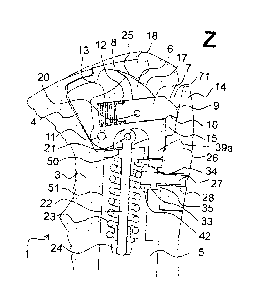
In the pole grip according to figure 1, the pole grip 1 is provided with a
blind hole from
below in the form of a cavity 5 for the pole tube 2. The handle body 3 has a
recess 4 in the
head area 31 in which a safety release for pulling upwards is provided on a
loop-shaped
device 70 attached to a hand holding device 69.
The loop-shaped device 70 is attached to the handle by means of the holding
mandrel 14,
which is located to a certain extent in a recess 16 in the handle body 3.
The holding mandrel 14 is not formed in one piece with the handle body 3, but
is part of a
mandrel block 26, which can be deflected sideways about a rotation axis 73 as
shown with
the arrow 72 in figure lc when pulling the loop.
To make this possible, the mandrel block 26 is provided with a through opening
28, which
runs essentially parallel to the running direction 30. In the handle body 3
there is a through-
opening 34. Furthermore, the mandrel block 26 has a hollow cylindrical
extension 33 in the
area of the through-opening 28, which has axial slots and which has a quasi-
circumferential
flange 42 directed outwards at the end projecting through the through-opening
34 into the
handle head 3. However, there is no really circumferential flange 42, but only
corresponding
segments separated from each other by the four distributed slots 43a.
Correspondingly, the mandrel block 26 can be pressed into the opening 34 in
the handle
body 3 during assembly with the elements 33/42, whereby the sections 42 facing
outwards
can be deflected inwards due to the flexibility of the sections 33. If the
outwardly directed
sections 42 have passed through the through-opening 34 into the inner cavity
51, they can
again deflect elastically radially outwards and then hook the mandrel block 26
in the opening
34.
In order to now fix the mandrel block 26 definitely in the opening 34 in the
handle body 3,
a fixing pin 27 is inserted from the outside through the opening 28 in the
mandrel block 26
until the inner end of this fixing pin 27 passes through the area 33. Once
this fastening pin
27 has been inserted, it is no longer possible to separate the fastening block
26 from the
handle body 3 without removing the fastening pin 27.
In the head area 31 of the handle body 3, a mounting block 6 is located in the
recess 4. This
can be rotated about a transverse axis of rotation 11 in a direction
perpendicular to the stick
axis and perpendicular to the running direction.
This fixing block 6 is braced downwards by the bracing pin / eye bolt 22,
which is attached
to the fixing block 6 by the transverse fixing pin 21. For this purpose, the
tensioning pin 22
projects downwards through a through-hole 50 into an axial receiving opening
51 and is
13
CA 03098773 2020-10-29
retained there by a spiral spring 23, at the free end of which the end nut 24,
possibly provided
with a spring end element, is retained at the free end of the tensioning pin
22.
In the mounting block 6, the locking pin 7 is also provided, which can be
moved against the
restoring force of a spiral spring 13, mounted in a recess 8. The locking pin
7 is braced with
its front tip 9 against the retaining pin 14, or strikes against a stop in the
fixing block 6 at a
slight distance from the retaining pin 14 in the rest position.
In recess 4, a release knob 18 is additionally provided, also rotatable around
the axle 11,
which is mounted in the axle hole 19. This release knob 18 has on the one hand
a round
sliding surface 25, which corresponds to the sliding surface 17. On the other
hand, this
release button 18 has two baffle openings 77 on the lateral flanks. The
transverse pin 20,
which is arranged in the locking pin through a transverse opening, is caught
in these baffle
openings.
If the release button is now pressed from above as shown in Figure 1 (e), it
deflects in a
clockwise direction and thereby swivels the mounting block slightly
counterclockwise
through the contacting surfaces 25/17 on the one hand and on the other hand
the locking pin
is pushed into the interior of the mounting block 6 through the links 77 via
the cross pin 20
against the spring force 13.
This opens the area 15, which is itself caught in the rest state by the front
area 9 of the locking
pin 7, and the loop 70, which was previously caught in the area 15, can be
removed upwards
from the slot through the area 71.
There are now two safety release mechanisms for such a grip head:
One safety release mechanism can be activated or comes into action if there is
a strong
upward pull on the loop, i.e. against the locking pin 7, for example by
placing the loop in the
concave area 10 on the lower surface of the locking pin. If a strong pull is
now exerted in
this direction, the fixing block 6 is swivelled upwards counter-clockwise
around the axis 11
against the spring force of the coil spring 23, as shown in Figure 1 (e), with
the tip 9 exposing
the area 15.
A second safety mechanism against lateral loads is provided by the fact that
the entire
mandrel block 26 can be swivelled as shown by the arrow 72 in Figure lc).
To ensure that this is done against a defined release force, there is, as
shown in Figure if)
and i)-p), a front surface 36 of the mandrel block, which is in contact with a
contact surface
37 on the handle head. A lower sliding surface 45 on the mandrel block 26
slides against a
sliding surface 46 on the handle body. A step projecting into the handle body
is now provided
14
CA 03098773 2020-10-29
in the contact surface 37. At the zenith, this step has a locking groove 39,
in which a
corresponding projection 39a of the fixing block 6 engages in the middle
position. In
addition, the projection 39a can project into an axial recess 40. On the
mandrel block 26
there are two projections 41 for engaging in the step of the surface 37. This
step 37 is
provided with two stop surfaces 44 each for a maximum rotational position of
the mandrel
block. On the one hand, the projections 41 each have an external stop surface
41b, which
comes into contact with the respective stop surface 44 at the maximum
rotational position of
the mandrel block 26, and on the other hand, they have a sliding surface 41a,
with which
they slide along surface 38 during rotation. Furthermore, the projections 41
have an inclined
stop surface 41c which, in the middle position, i.e. when the mandrel block 26
is not pivoted,
comes into contact with the two flanks of the V-shaped extension 39a of the
fixing block 6.
The contouring of the contact surface 37 together with the corresponding
surface structuring
of the front surface 36 of the mandrel block 26 means that the mandrel block
can only be
deflected sideways along the arrow 72 after a trigger force has been exceeded.
The force is
determined by the fact that the contact surface 41c, when the rotary movement
of the mandrel
block 26 begins, must first swivel the fastening block 6 upwards as a result
of the V-shaped
extension area 39a, which is to a certain extent in the way. This upward
pivoting movement
of the fixing block 6 is determined by the spring force of the spring 23. The
mandrel block
can be deflected until the corresponding contour 41b on the mandrel block 26
comes into
contact with the stop 44. This is typically an angular range of approx. 40 -
90 , measured to
both sides. However, a deflection of up to 180 may also be possible.
Once such a deflection has taken place and no more force is applied, the
mandrel block 26
is then returned to the vertical position due to the restoring force of the
spring 23, which is
transmitted to the mandrel block 26 via the range 39a and the corresponding
flank 41c, and
then, if necessary, engages again in this vertical position via corresponding
contours.
If the mandrel block 26 or the entire handle head is loaded as intended by the
loop 70 exerting
a downward pull, the proposed design prevents the mandrel block 26 from
inadvertently
swinging sideways into the safety deflection.
Figure 2 shows a second example. Parts that are equivalent or the same in
themselves are
marked according to the example in Figure 1, and not all parts are therefore
marked with
reference numerals again for clarity.
In this case, the mandrel block 26 does not have a through-hole, but a recess
or a blind hole
75. In this blind hole 75, a bracing pin 53, which runs essentially in the
running direction 30,
15
CA 03098773 2020-10-29
is pivotably mounted in the through-hole 61 in the mandrel block 26 via a
cross pin or
fastening pin 61.
This bracing pin 53 protrudes through a through-hole 56 into a cavity 58 in
the handle head.
In this cavity 58 a spiral spring 55 is provided, which circulates the tension
pin 53. At the
free end, an end nut is screwed onto the bracing pin 53 and secured against
unscrewing by
suitable means, whereby corresponding spring end elements are provided in
between both
on the side of the end nut 52 and on the stop on the back of the through-hole
56.
In this case, as can be seen in particular from Figures 2f) and i) - p), the
front surface 36 of
the mandrel blocks 26 and the corresponding contact surface 37 have a slightly
different
design than in the first design example. On the one hand, there are to a
certain extent two
lateral flanks 78 in the contact surface 37 on the body of the handle, so the
contact surface
37 is implemented as a vertical channel in which the mandrel block engages
with its surface
36. Likewise, there are two lateral bevelled flanks 78a in the front face 36
of the mandrel
block 26, which lie in contact with the flanks 78 in the contact face 37 when
the mandrel
block 26 is not laterally deflected.
In addition, there is a spherical-calotte-shaped recess 59 below the through-
opening 56 in
the handle body in area 37 of the handle body, and a corresponding spherical-
calotte-shaped
bulge 60 is provided in area 36 of the mandrel block 26.
In the central middle position for the intended use, i.e. when the fixing
mandrel 14 is directed
vertically upwards, the calotte 60 of the mandrel block 26 engages in the
recess 59 and,
together with the lateral flanks 78 and 78a respectively, stabilises the
fixing block 26 in the
middle position by means of a positive fit.
If, in this example, a lateral pull is exerted on the holding mandrel 14, a
force must be applied
on the one hand by the form fit in contours 59 and 60. However, the entire
mandrel block
must also be pulled out of the grip head against the spring force of the
spiral spring 55 slightly
along the axis of the bracing pin 53, so that the mandrel block can slide over
the flanks 78
or 78a in one or the other lateral direction and allow rotation. This ensures,
in this case by
means of the appropriate setting of the nut 52 or a corresponding end element
62, an
adjustable release force for the lateral rotation in the sense of the above-
mentioned second
safety release.
In order to ensure the most stable construction possible and a safety release
also at the top,
it is possible to provide a bottom extension 79 with a through-hole in the
mounting block.
This through-opening is also passed through by the bracing pin 53 and the end
nut 52 is in
16
CA 03098773 2020-10-29
the stop with the corresponding extension 79. This means that here the safety
release is not
implemented via an axial spring 23 for the fixing block when there is a pull
upwards, but
here, when a strong pull is exerted on a loop 70 upwards and a torque is
correspondingly
initiated/exerted via the locking pin, in the illustration according to Figure
2e the fixing block
6 is turned away/released around the axis of rotation 11 in an anti-clockwise
direction and
against the compressive force of the spiral spring 55 analogous to the first
safety solution
mentioned above, while releasing the range 15.
The intended release of the loop 70 from the holding mandrel is again ensured
by a release
button 18 with corresponding links (grooves) 77, which is connected to the
locking pin 7 via
the transverse axis 20, which can be moved in the slotted hole 48.
A third example is shown in Figure 3. Here at least the lower section 65 of
the holding
mandrel is made in one piece and from the same material as the handle body.
The first safety
release and the design of the mounting block 6, locking pin 7 including
bracing pin 22 and
spiral spring 23 is analogous to the design example 1 described above.
Here, however, an upper area 66 of the holding mandrel 14 is formed from a
soft and
elastically deformable/flexible plastic. There is a transition area 67 between
the lower area
65 and the upper area 66.
Typically, such a grip head is produced in a two-component injection moulding
process,
using a different material for the 66 area than for the 65 area.
If in this case, a lateral load is now applied to the loop or a rotation is
applied, the loop is
moved slightly upwards on one side and then comes into the area of the upper
soft and
bendable area 66. As the upper area 66 is bendable, the hook can then also be
made without
a mechanical safety release with coil springs by rotating the fixing block 6
around the axis
11.
The transition area can be designed differently, different possibilities are
shown in figures
3d-l.
Thus, it is possible to provide a somewhat rounded cuboid axial extension 68
according to
figure 3g. Alternatively, it is possible to provide a bridge-like extension
made of hard
material 68 as shown in Figure 3h. The advantage of such a design is that the
softer material
can flow into the bridged area of the clamp 46 and thus ensure good adhesion
between the
hard area 65 and the upper area 66.
Another variant is shown in Figure 3i, where extension area 68 is an
essentially circular
cylindrical trunnion.
17
CA 03098773 2020-10-29
In order to ensure a better connection between the upper area 66 and the lower
area 65, as
shown in Figure 3j, a somewhat spherical extension can also be provided at the
free end of
extension 68.
Also for a better connection between the upper area 66 and the hard lower area
65 it is
possible to provide a through opening in the extension 68, as shown in figure
3k.
Alternatively, as shown in Figure 31, or in addition, it is possible to
provide 68 ribs or
serrations on such an extension so that the soft material in the two-component
injection
moulding process not only flows around but also partially flows into this
extension 68.
A further example is shown in Figure 4. As a significant difference compared
to the example
shown in Figure 1, it should be emphasized that here essentially the entire
mechanism for
the holding mandrel is combined in one unit, which can be assembled beforehand
and then
inserted into recess 4 in the stick handle 1 and fixed in this recess 4.
An essential element of this design is an additional retaining block 82, which
is shown
separately in two perspective views, especially in Figures 4 g) and h). This
retaining block
82 is intended as a support for the mandrel block 26. On a surface 87 of the
retaining block
82 facing the mandrel block 26, a hollow circular cylinder extension 85 with
an axial opening
86 is provided. The mandrel block 26 has a corresponding recess 28, which can
be pushed
onto the hollow cylinder extension 85. The mandrel block 26 can then be
attached to the
holding block 82 with a screw 88. Due to the design with the hollow
cylindrical extension
85, the mandrel block 26 can then be rotatably mounted on the retaining block
82.
Furthermore, the retaining block 82 has two arms 84, at the ends of which two
through
openings 83 are provided. With a retaining pin 81, this retaining block 82 can
be connected
to the mounting block 6 and the release button 18. This is done by first
pushing the release
button 16 from above over the mounting block 6, into which the locking pin 7
with the spring
13 with the cross pin 20 can already be captured and inserted. Likewise, the
holding block
82 with the two arms 84 is pushed on from below until the through openings 92,
83 and 98
are aligned and the holding pin 81 can be inserted. In doing so, the V-shaped
extension 39a
of the holding block 6 engages in a receiving pocket 94 in the mandrel block
26. The unit
formed in this way from the elements 6, 18, 26 and 82 can be prefabricated and
then inserted
into the recess 4 in the stick handle 1 and fastened in this recess 4 via the
fastening cross pin
99. After inserting the unit into the handle head and mounting the cross pin,
the compression
spring 23 with the two spring end caps is pushed from below through the handle
bore onto
the eye bolt 22 and fixed by means of the hexagon nut 24. In doing so, the
compression
18
CA 03098773 2020-10-29
spring 23 is pretensioned and thus the desired release force is also adjusted.
The curved slot
91 in the release button 18 also fixes this unit in the recess 4, yet its
elements can still move
to the required mass for the release and locking functions.
With regard to the engagement of the loop-shaped device 70 behind the holding
mandrel 14,
this fourth example functions in essentially the same way as the first
example: if the loop 70
is pushed over the holding mandrel 14 from above, the locking pin 7 moves into
the fastening
block 6 against the force of the coil spring 13, and after the loop 70 has
reached the holding
area 15, the locking pin 7 pushes against the holding mandrel 14 again and
thus locks the
loop 70 in the area 15.
Like the first example, the safety release also works in the same way when the
loop 70 is
pulled upwards: In this case, the force from below on the concave area 10 of
the locking pin
7 swivels the fixing block 6 around the axis 81 against the force of the
spring 23 (compare
in particular Figure 4e, there movement of block 6 counterclockwise), so that
loop 70 is
released.
The possible lateral safety deflection of the holding mandrel 14 against a
controlled release
force is ensured here by the engagement of the V-shaped extension 39a of the
fixing block
6 in the receiving pocket 94 in the mandrel block 26. This receiving pocket 94
has two
correspondingly V-shaped flanks 95, and if the mandrel block 26 is turned
around the axis
88 by e.g. lateral pulling on the loop, this can only be done by the flanks 95
of the receiving
pocket 94 in the mandrel block 26 sliding on the flanks of the extension 39a
of the fastening
block 6, thus deflecting the fastening block 6 upwards against the force of
the spring 23.
This also allows the lateral deflection of the mandrel block 26 against this
spring force and
after loading, the mandrel block 26 jumps back into its original vertical
starting position also
because of this spring force.
A further example is shown in Figure 5. It has a release mechanism similar to
the example
shown in Figure 4, but additionally has a safety release around a second axis
of rotation.
Specifically, the mandrel block 26 cannot be tilted downwards as intended when
the hand
strap is loaded, but can be tilted backwards slightly when the hand strap is
loaded, so that
the eye of the hand strap can slide out just between the locking pin and the
retaining mandrel
14. In this way, a safety release around all three axes can be guaranteed to a
certain extent.
In this example, an additional exchangeable cover is provided, which allows
111 accessories
made of hard plastic, for example a protector for the hand (so-called gate
guard, for example
for slalom competition and training), to be attached to the pole handle using
an adapter piece.
19
CA 03098773 2020-10-29
In perspective views in a) and b) the stick handle is shown with a closing
cover 114 according
to this design example, while in the perspective views in c) and d) this cover
is replaced by
an insert or adapter piece 111, typically made of metal, which has an internal
thread 120 for
a fastening screw, for example for a (not shown) hand guard. Typically, the
hand guard is
attached with its other free end at the bottom of the pole tube directly below
the handle body.
The cover 114 can be seen better in the exploded view according to figure 5e.
The cover
inserted in figures a) and b) is cover 106. This cover 106 has a cover plate
114 which, when
inserted, forms the surface of the upper part of the handle. This cover plate
114 is attached
to the cane handle by means of a mounting stub 107 which engages in a
corresponding blind
hole or exposed area in the handle body and/or mounting block 7. At the lower
end of this
mounting stub 107 there is a transverse through-hole. The cover 106 can be
fixed in the
handle body with the cross pin 11 when inserted. Typically, a stick handle is
sold with cover
160 inserted in this way. If a user now wishes to attach a hand protector to
such a handle, for
example, only the cross pin 11 needs to be removed, the cover 106 can be
removed from the
handle head, and the adapter piece 111 for the hand protector can now be
inserted into the
recess that is now released. This insert also has a mounting stub 107, at the
lower end of
which a transverse through-hole 113 is provided for the cross pin 11. The
adapter piece 111
can thus be fixed in the handle head in the same way as the cover 106.
However, the adapter
piece 111 now has a collar or circumferential flange 112 at the top, and the
fastening stub
107 is designed as a blind hole open at the top with an internal thread. The
fastening screw
of an accessory can now be screwed into this internal thread 120 without
further ado, and
the accessory is thus firmly fastened to the handle head without further
manipulation.
In Figure 5 e), particularly in a general view with g), it can now also be
seen how in this
example the retaining mandrel 14 is mounted around two rotary axes in the
sense of a further
improved safety release. The mandrel block 26 is in turn rotatably attached to
a retaining
block 82 by means of a screw 88. Here, too, the retaining block 82 has a
hollow cylinder
extension 85 provided for this purpose. The opening in this extension serves
as a receiving
opening for the screw 88 and is then also the axis of rotation for the mandrel
block 26 about
the first axis 86. Here, too, the retaining block 82 has two fork arms 84, at
the free ends of
which two aligned through-openings 83 are provided. Via these openings in 83,
the retaining
block 82 can be attached to the mounting block 6 with the retaining pin 81.
For this purpose,
the mounting block 6 has two lateral recesses and a through opening 92 in
these. The two
fork arms 84 of the retaining block 82 can be pushed into or onto these
recesses until the
20
CA 03098773 2020-10-29
through openings 83 are aligned with the through opening 92, then the cross
pin 81 can be
inserted. Here too, the eyebolt 22 is hinged to the mounting block 6 with the
fixing pin 21.
In the mounting block 6, the locking pin 7 is also mounted in the recess 8 in
this case so that
it can be moved against the return of the spiral spring 13. The locking pin 7
is captured by
the cross pin 20, which passes through the cross hole 64, protrudes beyond it
on both sides,
and engages in the guide slot 48 in the mounting block 6. Accordingly, the
locking pin 7 can
only be moved in the recess 8 within the limits defined by the oblong hole 48.
The locking
pin 7 braces the eye of the hand strap with its tip, for this purpose a
concave area 10 is also
provided here, which limits the area 15.
The unit thus formed, consisting of holding block 82, mandrel block 26 and
fixing block 6,
is held in the recess 4 in the handle head by the bracing pin (eyebolt) 22
fixed by the fixing
pin 21, which is braced from below via cavity 5 with the spiral spring 23 and
fixed with the
end nut 24.
On the other side, the release button 18 on this unit is also caught by the
cross pin 21. The
cross pin protrudes with its two free ends beyond the lateral surface of the
mounting block
6 and engages in the two curved oblong holes 101 of the release button 18. The
release knob
18 has a transverse through-hole 100, and is mounted in the handle head so
that it can be
tilted around the axis of this transverse pin 11 via the transverse pin 11,
which passes through
the through-hole 109 in the handle body. If the release button 18 is pressed
down in the rear
area, i.e. at the holding mandrel 14, the cross pin 21 is displaced in the
running direction due
to the slotted link 101 and thus the locking pin 7 is pushed further into the
recess 8 against
the force of the spring 13, thus releasing the area 15. This is the
manipulation that is carried
out when the user wants to release the hand strap from the grip body as
intended.
As far as the release around the first axis of rotation is concerned, this
functions in the
example shown in Figure 5 in the same way as in the example in Figure 4.the
mandrel block
is mounted so that it can rotate around axis 88 on the retaining block 82,
whereby here too a
V-shaped extension 39a on the retaining block 82 engages in a receiving pocket
94 in the
mandrel block 26. When the mandrel block is rotated about the first axis of
rotation, the
extension 39a moves along the inclined flanks 95 and moves the mounting block
6 upwards
against the return of the spring 23.
In addition, this design example now includes a release around the second
rotation axis 121
perpendicular to the direction of travel and perpendicular to the stick axis.
This slight tilting
possibility as a safety release is realized by the saddle 119, on which the
unit consisting of
21
CA 03098773 2020-10-29
holding block 82 and mandrel block 26 is placed. On the one hand, with a
downward
extension 103 of the holding block 82, and on the other hand with the contact
area 105,
which is formed by the lower part of the front surface 36 of the mandrel block
26. Pulling
on the retaining mandrel 14 in the illustration in Figure 5 g) now causes the
unit formed by
retaining block 82 and mandrel block 26 to tilt clockwise to the right about
the second axis
121. At the same time, the fixing block 6 moves around the axis 81 slightly
counter-
clockwise, so that the area 15 is opened slightly, and the fixing block 6
moves slightly to the
right. This is possible because the cross pin 11 can be moved in an elongated
recess 110 of
the mounting block 6, which is open at the top. During this displacement, the
release button
18 remains in its normal position. This now causes the cross pin 21 to move
upwards in the
curved slot 101, thus pushing the cross pin to the left and the locking pin 7
into the fixing
block 6. In other words, the fastening pin 7 does not follow the displacement
of the fastening
block 6 to the right as shown in Figure 5 g) and thus the eyelet is released
from the area 15.
Another feature that distinguishes the example in Figure 5 from that in Figure
4 is the cover
102, which has two opposite transparent or even through-opening areas 115 on
either side
of the handle body, through which the coil spring 23 is visible. The cover
102, which may
be made of transparent or translucent material, for example, and may be
decorated in whole
or in part, can now be snapped onto the handle body from behind, covering the
areas 115. In
this design example the cover 102 is to a certain extent in the shape of a
saddle, but it is also
possible to provide two such covers for each side individually. Furthermore,
it is possible to
replace the aforementioned transparent or semi-transparent covers with covers
that are
provided with a non-slip surface to increase the non-slip surface of the
handle and thus create
more grip. The non-slip surface can be created, for example, by a sprayed-on
skin of a softer
plastic material or by a structured, roughened surface.
LIST OF REFERENCE SIGNS
1 pole handle 8 recess in 6 for 7
2 cane pipe 9 front area of 7
3 handle body 10 concave area at tip of 7
4 recess in 3 11 rotation axis of 18,
cross pin
5 cavity in 3 for stick pipe 12 rear area of 7
6 mounting block 13 spiral spring
7 locking pin 14 holding mandrel
22
CA 03098773 2020-10-29
15 area for attached loop/eyelet 40 axial recess
16 recess in 3 for 14 41 projection on 26
17 round sliding surface at 6 41a siding surface of 41 to 38
18 release button 41b stop surface of 41 to 44
19 axle hole for 11 41c stop surface of 41 to 39a
20 cross pin of 7 42 extendedarea, snap-in range
21 fixing pin of 33
22 tension pin, eye bolt 43 cylinder area of 33
23 spiral spring 43a slots in 33
24 trap nut 44 abutment surface
25 round sliding surface at 18 45 lower sliding surface at 26
26 mandrel block 46 sliding surface on handle
27 fixing pin from 26 body corresponding to 45
28 through opening in 26 for 27 47 fastening eyelet of 22
29 pole axis 48 guide slot
30 walking direction 49 opening in 18 for 11
31 head area of 1 50 opening from 4 to 51
32 front extension of 1 in the 51 axial location hole for axial
head area spring from mounting block
33 fastening element for 27, 52 trap nut
detent and turning extension 53 eyebolt, tension pin of 26
at 26 5 fastening eyelet of 53
34 opening in handle body for 55 coil spring
26/27 56 opening for 53 in stick
handle
35 cylinder extension range from 57 spring end element
33 58 cavity for 53/55
36 front area of 26 59 concave-calotte-shaped recess
37 contact surface on handle in the handle body
body 60 dome shaped projection at 26
38 sliding surface for contour at 61 fixing pin for 53 to 26
26 on handle body 61a cross hole for 61 in 26
39 groove in 38 62 completion element
39 V-shaped extension at 6 63 washer
23
CA 03098773 2020-10-29
64 cross hole in 7 for 20 93 opening for 21
65 lower mandrel area 94 receptacle for 39a
66 upper mandrel area 95 sloping flanks of 94
67 contact range between 65 and 96 front boundary wall of 94
66 97 expansion 1n28 for head of
68 expansion of 65 88
69 hand holding device 98 opening for 81 of 16
70 loop, ring or eyelet shaped 99F fixing cross pin
device 100 through opening for 11
71 insertion slot through 18
72 lateral deflection 101 curved oblong hole in 18 for
73 rotary axis 21
74 lower range of 26 102 cover
75 back hole in 26 103 continuation on 82
77 guide slot for 20 in 18 104 abutment surface for 105
78 sided flanks/raises of 37 105 abutment area of 26
78a side edges from 36 at 26 to 106 cover
the system at 78 107 fixing butt
79 bottom side extension of 6 108 opening in 107 for 11
80 opening in 79 for 53 109 opening in 3 for 11
81 holding pin 110 long recess in 6 for 11
82 holding block 111 adapter piece
83 opening in 84 112 circumferential flange of 111
84 fork arm of 82 113 opening in 111 for 11
85 hollow circle cylinder 114 cover plate of 106
extension 115 viewing opening or viewing
86 axis opening in 85 window in 3
87 front area of 82 116 abutment for 103
88 screw 117 upper attachment point of 6
89 passage for pin 22 118 slide gate on underside of 18
90 opening for 87 for 117
91 slot for 87 119 saddle
92 opening in 6 for 81 120 female threaded hole in 111
24
CA 03098773 2020-10-29
121 Second axis of rotation