Note : Les descriptions sont présentées dans la langue officielle dans laquelle elles ont été soumises.
CA 03098800 2020-10-29
WO 2019/211681
PCT/IB2019/052952
THREADED LOCKING STRUCTURES FOR AFFIXING
BONE ANCHORS TO A BONE PLATE
CROSS REFERENCE TO RELATED APPLICATIONS
[0001] This application is related to U.S. Patent Application Serial Nos.
15/926,390,
filed on March 20, 2018, in the name of Bosshard, et al.; and 15/940,761,
filed March 29, 2018,
in the name of Bosshard, et al., the disclosures of each of which are hereby
incorporated by
reference as if set forth in their entireties herein.
TECHNICAL FIELD
[0002] The present invention relates to bone plates and bone anchors for
coupling to the
bone plates, and particularly relates to threaded locking structures defined
within a fixation hole
of a bone plate for locking with a head of a bone anchor.
BACKGROUND
[0003] Bone plate systems for the internal fixation of bone fractures are well
known.
Conventional bone plate systems are particularly well-suited to promote the
healing of a fracture.
A bone anchor, such as a bone screw, is inserted through a fixation aperture
or hole in a bone
plate and is threaded into bone to compress, neutralize, buttress, tension
bend, and/or bridge the
fracture ends together. Bone screws that are capable of locking with the bone
plate can be
employed to transfer loads from one fractured bone part, over a plate, and
onto another fractured
bone part without drawing the bone against the plate, and to avoid loosening
or backing out the
bone screws with respect to the plate (which can lead to poor alignment and
poor clinical
results). One known embodiment of such a screw employs a screw head with
external threads
for engaging with a corresponding thread on the inner surface of a fixation
hole to lock the screw
to the plate. These screws, which are hereinafter referred to as "locking
screws" or "locking
compression screws", and which can include standard-type locking screws that
are configured to
lock within fixation hole substantially only at a "nominal" orientation
whereby the central screw
axis is substantially aligned with the central hole axis, as well as "variable-
angle" (VA) locking
screws that are configured to lock within a fixation hole at either a nominal
orientation or an
- 1 -
CA 03098800 2020-10-29
WO 2019/211681
PCT/IB2019/052952
"angulated" orientation whereby the central screw axis is oriented at an acute
angle with respect
to the respective central hole axis.
SUMMARY
[0004] According to an embodiment of the present disclosure, a bone plate
includes at
least one hole extending through the bone plate from an upper plate surface to
a lower plate
surface along a central hole axis that is oriented along an axial direction.
The at least one hole
defined by an interior surface of the bone plate. The interior surface further
defining a plurality
of columns sequentially located about a circumference of the interior surface
and a plurality of
recesses located circumferentially between the columns. Each of the columns
defines a plurality
of thread segments each defining a root, a first thread surface extending from
the root to a first
crest, and a second thread surface extending from the root to a second crest.
At least a portion of
the first and second thread surfaces are offset from one another at a thread
angle. The thread
angle of at least one of the thread segments is in a range of about 5 degrees
to about 59 degrees.
BRIEF DESCRIPTION OF THE DRAWINGS
[0005] The foregoing summary, as well as the following detailed description of
illustrative embodiments of the present application, will be better understood
when read in
conjunction with the appended drawings. For the purposes of illustrating the
locking structures
of the present application, there is shown in the drawings illustrative
embodiments. It should be
understood, however, that the application is not limited to the precise
arrangements and
instrumentalities shown. In the drawings:
[0006] Fig. 1 is a perspective view of a bone fixation system that includes a
bone plate
and a plurality of locking screws disposed within locking holes of the bone
plate, according to an
embodiment of the present disclosure;
[0007] Fig. 2 is a sectional side view of the bone fixation system taken along
section
line 2-2 in Fig. 1 affixed to a plurality of bone segments;
[0008] Fig. 3 is a sectional perspective view of a locking hole of the bone
plate
of Figs. land 2;
[0009] Fig. 4 is another sectional perspective view of the locking hole of
Fig. 3;
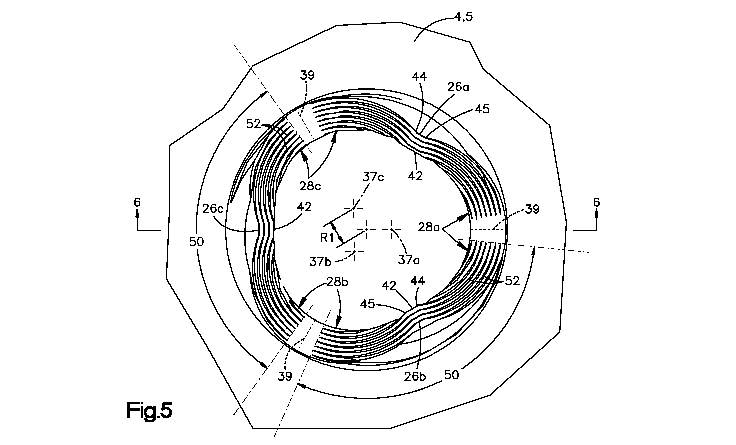
[0010] Fig. 5 is atop view of the locking hole of Fig. 3;
[0011] Fig. 6 is a side sectional view of the locking hole taken along section
line 6-6 in
Fig. 5, showing a threaded locking structure defined by an interior surface of
the locking hole,
wherein the threaded locking structure is configured to lock with a locking
bone screw;
- 2 -
CA 03098800 2020-10-29
WO 2019/211681
PCT/IB2019/052952
[0012] Fig. 7 is an enlarged sectional view of the threaded locking structure
shown in
Fig. 6;
[0013] Fig. 8 is a side view of a head of a variable-angle (VA) locking screw
configured to be locked to the bone plate of Fig. 1 within one of the locking
holes;
[0014] Fig. 9 is a sectional side view showing threaded engagement and "timing-
error"
compensation between external threads on the head of the VA locking screw
shown in Fig. 8 and
internal threads of the locking structure shown in Fig. 6 during locking;
[0015] Fig. 10 is a sectional side view showing another threaded engagement
and
plastic and elastic deformation between the external threads on the head of
the VA locking screw
and internal threads of the locking structure shown in Fig. 6 after locking;
[0016] Fig. 11 is a sectional side view of the head of the VA locking screw of
Fig. 8
during locking at a nominal orientation within the locking hole shown in Fig.
6;
[0017] Fig. 12 is an enlarged view of region N in Fig. 11, showing deformation
of the
internal threads of the locking structure against the external threads on the
head of the VA
locking screw during locking at a nominal orientation;
[0018] Fig. 13 is a sectional side view of the head of the VA locking screw of
Fig. 8
during locking at an angulation of 15 degrees within the locking hole shown in
Fig. 6;
[0019] Fig. 14 is an enlarged view of region N in Fig. 13, showing deformation
of the
internal threads of the locking structure against the external threads on the
head of the VA
locking screw during locking;
[0020] Fig. 15 is a sectional side view of the head of the VA locking screw of
Fig. 8
during locking at an opposite angulation of 15 degrees within the locking hole
shown in Fig. 6;
[0021] Fig. 16 is an enlarged view of region N in Fig. 15, showing deformation
of the
internal threads of the locking structure against the external threads on the
head of the VA
locking screw during locking;
[0022] Fig. 17 is a side sectional view of a locking hole, according to
another
embodiment of the present disclosure;
[0023] Fig. 18 is a sectional profile view of internal threads of the locking
hole shown
in Fig. 17;
[0024] Fig. 19 is a partial sectional side view of the head of the VA locking
screw of
Fig. 8 locked at a nominal orientation within the locking hole shown in Fig.
17;
[0025] Fig. 20 is a partial sectional side view of the head of the VA locking
screw
locked at an angulation of 15 degrees within the locking hole shown in Fig.
17;
- 3 -
CA 03098800 2020-10-29
WO 2019/211681 PCT/IB2019/052952
[0026] Fig. 21 is a partial sectional side view of the head of the VA locking
screw
locked at an opposite angulation of 15 degrees within the locking hole shown
in Fig. 17;
[0027] Fig. 22 is a sectional profile view of internal threads of a locking
hole,
according to another embodiment of the present disclosure;
[0028] Fig. 23 is a sectional profile view of internal thread of a locking
hole, according
to another embodiment of the present disclosure;
[0029] Fig. 24 is a top plan view of a locking hole, according to another
embodiment of
the present disclosure, wherein a thread path of the roots of the internal
threading is shown;
[0030] Fig. 25 is a perspective view of a bone plate having a combination hole
that
includes a variable angle locking hole as illustrated in Fig. 3 and a
compression hole that is open
to the variable angle locking hole portion; and
[0031] Fig. 26 is a perspective view of a bone plate having a combination hole
that
includes a variable angle locking hole as illustrated in Fig. 17 and a
compression hole that is
open to the variable angle locking hole portion.
DETAILED DESCRIPTION OF ILLUSTRATIVE EMBODIMENTS
[0032] The present disclosure can be understood more readily by reference to
the
following detailed description taken in connection with the accompanying
figures and examples,
which form a part of this disclosure. It is to be understood that this
disclosure is not limited to
the specific devices, methods, applications, conditions or parameters
described and/or shown
herein, and that the terminology used herein is for the purpose of describing
particular
embodiments by way of example only and is not intended to be limiting of the
scope of the
present disclosure. Also, as used in the specification including the appended
claims, the singular
forms "a," "an," and "the" include the plural, and reference to a particular
numerical value
includes at least that particular value, unless the context clearly dictates
otherwise.
[0033] The term "plurality", as used herein, means more than one. When a range
of
values is expressed, another embodiment includes from the one particular value
and/or to the other
particular value. Similarly, when values are expressed as approximations, by
use of the antecedent
"about," it will be understood that the particular value forms another
embodiment. All ranges are
inclusive and combinable.
[0034] The terms "approximately" and "substantially", as used herein with
respect to
dimensions, angles, and other geometries, takes into account manufacturing
tolerances. Further,
the terms "approximately" and "substantially" can include 10% greater than or
less than the stated
- 4 -
CA 03098800 2020-10-29
WO 2019/211681
PCT/IB2019/052952
dimension or angle. Further, the terms "approximately" and "substantially" can
equally apply to
the specific value stated.
[0035] Standard-type locking screws and VA locking screws can both be
susceptible to
a phenomenon referred to herein as "timing error," whereby factors relating to
a bone plating
procedure can cause an axial misalignment between external threads on the head
of the bone
screw relative to corresponding internal threads of a locking hole extending
through the bone
plate. Moreover, VA locking screws have a tendency to cause cross-threading
within a locking
hole in which they are inserted, particularly when the VA locking screw is
inserted in the locking
hole at an angulated orientation. Cross-threading can be caused by the
external threads on the
screw head not fitting within and thus cross-threading the internal threads of
the locking hole.
Regions of contact between the crests of the screw head threads and portions
of the internal
threads, particularly at or near the crests of the internal threads, can be
particularly susceptible to
cross-threading. Timing error and cross-threading are problematic because they
reduce the
interference fit (also referred to as the "form-fit") between the internal
threads of the aperture
and the screw head threads, which can reduce stability between the screw head
and the locking
hole. The embodiments disclosed herein pertain to locking structures employed
within a locking
hole, which locking structures define internal threads having geometries that
can avoid or at least
reduce contact with the screw head crests. The internal threads can also
deform in a direction
along a central axis of the hole responsive to timing error. In this manner,
the threaded locking
structures described herein can lock with the heads of both standard-type and
VA locking screws
in a manner inhibiting or at least reducing cross-threading.
[0036] Referring to Fig. 1, a bone fixation system 2 includes a bone plate 4
having a
plate body 5 that defines therein one or more fixation holes, such as variable-
angle (VA) locking
holes 6. The VA locking holes 6 are configured to receive anchor members, such
as locking
screws 8, for example, that are configured to affix the bone plate 4 to one or
more portions of
bone. The plate body 5 defines internal threads 9 within the VA locking holes
6. Accordingly,
the internal threads 9 can also be referred to as "plate hole threads" or
simply "plate threads" or
"hole threads." The hole threads 9 traverse locking structures, such as
columns 26, defined
within the VA locking holes 6. Thus the locking structures and columns 26 can
be referred to as
"threaded locking structures" and "threaded columns", respectively. The
threaded columns 26
are configured such that, during insertion of a locking screw 8 within the VA
locking hole 6, a
screw shaft 25 of the locking screw 8 bypasses the columns 26, which in turn
engage external
threads 29 on the screw head 27 of the locking screw 8 in a manner providing
enhanced locking
engagement between the locking screw 8 and the bone plate 4, as set forth in
more detail below.
- 5 -
CA 03098800 2020-10-29
WO 2019/211681
PCT/IB2019/052952
[0037] The bone plate 4 can be a bridge plate, as shown, although other bone
plate
types and configurations are within the scope of the present disclosure. The
plate body 5 can
define a first end 10 and a second end 12 spaced from each other along a
longitudinal direction X
and a first lateral side 14 and a second lateral side 16 spaced from each
other along a lateral
direction Y that is substantially perpendicular to the longitudinal direction
X. The bone plate 4
can also define an upper plate surface 18 configured to face away from the
bone and an opposed
lower plate surface 20 configured to face the bone. The upper and lower plate
surfaces 18, 20
are spaced from each other along a vertical direction Z substantially
perpendicular to each of the
longitudinal direction X and the lateral direction Y.
[0038] It is to be appreciated that, as used herein, the terms "longitudinal",
"longitudinally", and derivatives thereof refer to the longitudinal direction
X; the terms "lateral",
"laterally", and derivatives thereof refer to the lateral direction Y; and the
terms "vertical",
"vertically", and derivatives thereof refer to the vertical direction Z.
[0039] The VA locking holes 6 extend axially from the upper plate surface 18
to the
lower plate surface 20 along a central hole axis 22. In the depicted
embodiment, the central hole
axis 22 is oriented along the vertical direction Z, although in other
embodiments the central hole
axis 22 of one or more of the VA locking holes 6 can be oriented at an oblique
angle with respect
to the vertical direction Z. As used herein, an "axial direction" is defined
as the direction along
which the central hole axis 22 extends. Moreover, the directional terms
"axial", "axially", and
derivatives thereof refer to the axial direction. Thus, as used herein, the
directional term "axially
upward" and derivatives thereof refers to the axial direction from the lower
plate surface 20
toward the upper plate surface 18. Conversely, the term "axially downward" and
derivatives
thereof refers to the axial direction from the upper plate surface 18 toward
the lower plate surface
20. Thus, "axially upward" and "axially downward" are each mono-directional
components of
the "axial direction", which is bi-directional.
[0040] The plate body 5 and the locking screws 8 can each comprise one or more
biocompatible materials, such as titanium, titanium alloys (e.g., titanium-
aluminum-niobium
(TAN) alloys, such as Ti-6A1-7Nb), stainless steel, cobalt base alloys,
composite materials, and
polymeric materials and/or ceramic materials, by way of non-limiting examples.
Preferably, the
plate body 5 material is less hard than the locking screw 8 material. This
parameter contributes
to the locking characteristics described below. In one example embodiment, the
plate body 5
primarily or entirely comprises titanium and the locking screws 8 primarily or
entirely comprise
TAN.
- 6 -
CA 03098800 2020-10-29
WO 2019/211681
PCT/IB2019/052952
[0041] Referring now to Fig. 2, the VA locking holes 6 can be configured to
provide
enhanced affixation with multiple types of locking screws 8, including
standard-type locking
screws 8a and VA locking screws 8b, each optionally having various lengths, so
as to allow a
physician to implant the bone plate 4 to one or more bones or bone segments as
desired. By way
of non-limiting example, as shown, the bone plate 4 can be coupled to a long-
bone 100 via
locking screws 8a, 8b in a manner affixing fractured segments 101, 102 of the
bone together.
The VA locking holes 6 described herein can lock with standard-type locking
screws 8a at a
nominal orientation whereby a central screw axis 23 thereof is substantially
aligned with the
central hole axis 22. The VA locking holes 6 can also lock with VA locking
screws 8b at either
a nominal orientation or an "angulated" orientation whereby the central screw
axis 23 is oriented
at an acute angle Al with respect to the respective central hole axis 22.
Acute angle Al can also
be referred to as the "angle of angulation" or simply the "angulation." Both
types of locking
screws 8a, 8b and their locking functionalities are described more fully in
U.S. Patent 9,314,284,
issued April 19, 2016, in the name of Chan et al. (the "Chan Reference"), the
entire disclosure of
which is incorporated by reference herein, as well as U.S. Patent Application
Serial Nos.
15/926,390 and 15/940,761, referenced above.
[0042] During a bone plating operation, the screw shaft 25 of a locking screw
8 can be
inserted through one of the VA locking holes 6 and driven into the underlying
bone 100. In
particular, rotation of the locking screw 8 causes its threaded screw head 27
to threadedly mate
with the VA locking hole 6. As a result, the screw head 27 fastens the bone
plate 4 to the
underlying bone 100 substantially without applying a compressive force onto
the bone plate 4
against the underlying bone 100. The bone plate 4 can be spaced from the
underlying bone 100
when locked to the threaded screw head 27. Alternatively, the bone plate 4 can
abut the
underlying bone 100 when locked to the threaded screw head 27.
[0043] It is to be appreciated that, during a plating operation, the first
locking screw 8
inserted through one of the VA locking holes 6 and into underlying bone 100
has the benefit of
being able to generally mate with the hole threads 9 so that crests of the
screw head thread 29
advance helically substantially along the troughs of the hole threads 9.
However, once the first
locking screw 8 is locked to the bone plate 4 thereby fastening the plate 4 to
the underlying bone
100, the subsequent locking screws 8 often lack the ability to have their
external thread crests
advance helically along the hole thread 9 troughs. This results because, once
the screw shafts 25
of these subsequent locking screws 8 advance through the VA locking holes 6
and threadedly
purchase into the underlying bone 100, the relative axial positions of the
screw head threads 29
and the hole threads 9 are substantially a function of the screw's threaded
purchase with the
- 7 -
CA 03098800 2020-10-29
WO 2019/211681
PCT/IB2019/052952
underlying bone 100. This axial misalignment of the screw head threads 29
relative to the hole
threads 9 is referred to herein as "timing error." As described in more detail
below, the threaded
columns 26, and thus the hole threads 9, can be configured to deform axially
to accommodate the
timing error associated with locking screws 8. Such deformation can inhibit or
at least reduces
cross-threading within the VA locking holes 6.
[0044] Referring now to Figs. 3 and 4, each of the VA locking holes 6 can be
defined
by an interior surface 24 of the plate body 5. Alternatively, the interior
surface 24 can be defined
by an insert fitted within an axial aperture of the plate body 5. Typically,
at least a portion of the
interior surface 24 is tapered as it extends axially downward. Thus, the
interior surface 24 is
configured to prevent the screw head 27 from passing completely through the VA
locking hole 6.
[0045] The interior surface 24 can define the columns 26. The columns 26
extend
axially between the upper and lower plate surfaces 18, 20. Within each (or at
least some of) the
VA locking holes 6, the columns 26 are sequentially located about a
circumference of the interior
surface 24. The interior surface 24 also defines a plurality of recesses 28
sequentially located
circumferentially between the columns 26. The recesses 28 extend axially
between the upper
and lower plate surfaces 18, 20. The columns 26 and recesses 28 can be evenly
spaced about the
circumference of the interior surface 24 within the VA locking hole 6.
However, in other
embodiments, the columns 26 and/or recesses 28 can be un-evenly spaced about
the
circumference of the VA locking hole 6.
[0046] The interior surface 24 can define an upper perimeter 30 of the VA
locking hole
6 at an interface with the upper plate surface 18 and a lower perimeter 32 of
the VA locking hole
6 at an interface with the lower plate surface 20. The upper and lower
perimeters 30, 32 can
each be circular in shape, although other shapes are within the scope of the
present disclosure.
The interior surface 24 can also define a lead-in surface 34 that tapers
axially downward from the
upper perimeter 30 to one or more of the columns 26. As shown, the lead-in
surface 34 can be
circumferentially interrupted by one or more of the recesses 28.
Alternatively, the lead-in
surface 34 can extend circumferentially continuously and uninterrupted along a
full revolution
about the central hole axis 22. The interior surface 24 can also define an
undercut surface 36 that
tapers axially upward from the lower perimeter 32. The undercut surface 36 can
extend
circumferentially continuously and uninterrupted along a full revolution about
the central hole
axis 22. Alternatively, the undercut surface 36 can be circumferentially
interrupted by one or
more of the recesses 28.
[0047] Referring now to Figs. 5 and 6, in an example embodiment, the VA
locking hole
6 can include three (3) columns 26 and three (3) recesses 28 evenly spaced
about the central hole
- 8 -
CA 03098800 2020-10-29
WO 2019/211681
PCT/IB2019/052952
axis 22. The columns 26 can include a first column 26a, a second column 26b,
and a third
column 26c evenly spaced about the central hole axis 22. The recesses 28 can
include: a first
recess 28a located circumferentially between the first and second columns 26a,
26b; a second
recess 28b located circumferentially between the second and third columns 26b,
26c; and a third
recess 28c located circumferentially between the third and first columns 26c,
26a. It is to be
appreciated that in other embodiments there can be fewer than three (3) or
more than three (3)
columns 26 and recesses 28, respectively.
[0048] As shown in Fig. 5, the first recess 28a can define a first recess axis
37a, the
second recess 28b can define a second recess axis 37b, and the third recess
28c can define a third
recess axis 37c. Each recess axis 37a-37c can be parallel with the central
hole axis 22, although
other recess axis 37a-37c orientations are possible. Each recess axis 37a-37c
can also be radially
spaced from the central hole axis 22 by radial distance Rl. Each of the
recesses 28a-28c can
define a portion of a downward-tapering frusto-conical shape that defines a
central cone axis
coincident with the respective recess axis 37a-37c. The frusto-conical shapes
of the recesses
28a-28c can be substantially identical. In the illustrated embodiment, the
frusto-conical shapes
are each a frustum of a right circular cone; however other recess geometries
can be employed.
Each recess 28 defines a radially-outermost region or trough 39. Each trough
39 can lie in a
plane that also includes the central hole axis 22. As shown in one such plane
in Fig. 6, the
troughs 39 can be oriented at an acute angle A2 in a range of about 5 degrees
to about 30 degrees
relative to the central aperture axis 22. The recesses 28 can be configured
such that the troughs
39 define the radially outermost locations of the VA locking hole 6, as
measured in any reference
plane that extends through the VA locking hole 6 and is orthogonal to the
central hole axis 22.
[0049] Each column 26 can define a first surface 42 substantially facing the
central hole
axis 22. The first surface 42 can also be referred to as an "innermost
surface" of the column 26.
The first surfaces 42 of the columns 26 can extend generally axially between
the upper and lower
plate surfaces 18, 20. The first surface 42 of each column 26 can also extend
between a first side
44 and a circumferentially opposed second side 45 of the column 26. The first
and second sides
44, 45 of each column 26 can define interfaces between the column 26 and the
circumferentially
adjacent recesses 28. For example, the first side 44 of the first column 26a
can define an
interface between the first column 26a and the third recess 28c; the second
side 45 of the first
column 26a can define an interface between the first column 26a and the first
recess 28a; the first
side 44 of the second column 26b can define an interface between the second
column 26b and
the first recess 28a; and so forth along the circumference of the interior
surface 24. The first
- 9 -
CA 03098800 2020-10-29
WO 2019/211681
PCT/IB2019/052952
surfaces 42 of the columns 26 can collectively define segments of another
downward-tapering
frusto-conical shape that defines a central cone axis coincident with the
central hole axis 22.
[0050] The hole threads 9 extend through the columns 26 and at least portions
of the
recesses 28 along one or more thread paths between the upper and lower plate
surfaces 18, 20.
The one or more thread paths can be a single thread path (i.e., single-lead),
a pair of non-
intersecting thread paths (i.e., double-lead), or three or more thread paths
(e.g., triple-lead, etc.).
The thread paths can be helical. Portions of the recesses 28 can optionally
circumferentially
interrupt the hole threads 9 so as to define a plurality of threaded regions
50 spaced about the
circumference of the VA locking hole 6, as shown. Each threaded region 50
carries one or more
thread segments 52 extending along the thread path(s). Axially aligned ones of
the thread
segments 52 can traverse a respective one of the columns 26 so as to define
column threads 54.
[0051] With reference to Fig. 6, the first surface 42 of each column 26 can
define a
column centerline 46 that is disposed circumferentially equidistantly between
the first and
second sides 44, 45 of the column 26. The column centerlines 46 of the columns
26 can lie in
respective planes that also include the central hole axis 22. In each column,
the column
centerline 46 can extend along the crests 56 of the column threads 54. Thus,
the column
centerline 46 can also be referred to as the "crest centerline" of the
respective column threads 54.
A root centerline 48 can extend along the roots 58 of the column threads 54.
In each column 26,
the crest centerline 46 and the root centerline 48 can both lie in a single
plane that includes the
hole axis 22. The crest centerline 46 can be oriented at an acute angle A3 in
a range from about
degrees to about 30 degrees relative to the central aperture axis 22. The root
centerline 48 can
also be oriented at an acute angle A4 in a range from about 5 degrees to about
30 degrees relative
to the central aperture axis 22. The crest and root centerlines 46, 48 can be
parallel, as shown.
The column threads 54 can also define a thread midline 60, which can lie in a
common plane
with the crest and root centerlines 46, 48 and the central hole axis 22. The
thread midline 60 can
define an acute angle AS in a range from about 5 degrees to about 30 degrees
relative to the
central aperture axis 22. In the illustrated embodiment, the thread midline 60
is parallel with,
and equidistantly spaced between, the crest centerline 46 and the root
centerline 48. It is to be
appreciated that, in other embodiments, the crest and root centerlines 46, 48
of a column 26 can
be oriented at an oblique angle relative to one another.
[0052] The crest centerline 46 can be radially spaced from the central hole
axis 22 by a
radial distance R2 measured along a reference plane M that is orthogonal to
the central hole axis
22 and located at the vertical center of the VA locking hole 6. Thus, the
reference plane M can
be characterized as the axial "mid-plane" of the VA locking hole 6. The thread
midline 60 can
- 10 -
CA 03098800 2020-10-29
WO 2019/211681
PCT/IB2019/052952
be radially spaced from the central hole axis 22 by a distance R3 measured
along the hole mid-
plane M. The root centerline 48 can be radially spaced from the central hole
axis 22 by a
distance R4 measured along the hole mid-plane M. Distance R2 can be
characterized as the
mean crest radius of the column threads 54. Distance R3 can be characterized
as the mean radius
of the column threads 54. Distance R4 can be characterized as the mean root
radius of the
column threads 54.
[0053] Referring now to Fig. 7, each of the thread segments 52 can define a
root 58, a
first thread surface 55 extending from the root 58 to a first, axially upper
crest 56. Each thread
segment 52 can also define a second thread surface 57 extending from the root
58 to a second,
axially lower crest 56. The first and second thread surfaces 55, 57 are offset
from one another at
an angle A6, which defines the thread angle of the column threads 54. The
thread angle A6 can
be in a range of about 20 degrees to about 40 degrees, preferably in a range
of about 25 degrees
to about 35 degrees, and more preferably about 30 degrees.
[0054] In embodiments where the hole threads 9 are double-lead threads, the
column
threads 54 can define a thread pitch P in a range of 0.2 mm to about 0.6 mm
and preferably about
0.4 mm and a thread lead L in a range of about 0.4 mm to about 1.2 mm and
preferably about
0.8 mm, each measured along the axial direction. The column threads 54 can
also define a
thread depth D measured from the crest centerline 46 to the root centerline 48
along the radial
direction R. The pitch P and lead L of the hole threads 9 are preferably
equivalent to the pitch
and lead of the screw head threads 29.
[0055] Referring now to Fig. 8, the VA locking hole 6 described above can be
configured to provide beneficial mating characteristics with the screw head 27
of the standard-
type locking screw 8a (Fig. 2) and the VA locking screw 8b. The screw head 27
of the VA
locking screw 8b can have a generally spherical outer surface 66 that defines
the external screw
head threads 29. The external screw head threads 29 of the VA locking screw 8b
define a first
thread profile 74 measured at the thread roots 75 and a second thread profile
76 measured at the
thread crests 77. As depicted, the threads profiles 74, 76 of the VA locking
screw 8b are
generally spherical, which provides the screw head 27 with a locking
functionality as it advances
within the VA locking hole 6. The external screw head threads 29 have a thread
angle of about
60 degrees.
[0056] With reference to Figs. 9 through 17, threaded engagement between the
VA
locking holes 6 and the VA locking screw 8b will now be described. Although
the following
description of threaded engagement between the screw head threads 29 and the
hole threads 9 is
made in reference to a single threaded column 26, it is to be appreciated that
the other columns
-11-
CA 03098800 2020-10-29
WO 2019/211681
PCT/IB2019/052952
26 in the VA locking hole 6 can engage with the screw head threads 29 in a
similar, cooperative
manner.
[0057] Referring now to Fig. 9, axial deformation of the column threads 54 is
shown,
which can compensate for timing error between the VA locking hole 6 and the VA
locking screw
8b. In this example, the timing error causes the screw head threads 29 to
transmit axially
downward forces to the column threads 54. The column threads 54 disclosed
herein are
configured to have axial flexibility, particularly at the crests 56 thereof
This allows the column
threads 54 to deform axially responsive to the transmitted axially downward
forces. One or more
of the crests 56 of the column threads 54 can be configured to deform downward
or upward, and
non-destructively, at a maximum axial deformation distance Z1 that is at least
substantially
equivalent to one half of the thread pitch P or to one half of the thread lead
L divided by the
number of leads. Accordingly, the maximum axial deformation distance Z1 can be
expressed by
the equation: Z1 = 0.5(P) = 0.5(L)/(N ) According to one example
embodiment, the lead L is
=
0.8 mm, the pitch P is 0.4 mm, the column threads 54 are double-lead (N = 2),
and the resultant
maximum axial deformation Z1 of the thread crest 56 is 0.2 mm. The axial
deformability of the
column threads 54 can avoid, or at least reduce the timing-error and thus,
avoid or at least reduce
the occurrence of cross-threading within the VA locking hole 6.
[0058] Referring now to Fig. 10, radially outward deformation of the column
threads
54 is shown, such as, for example, to lock to the VA locking screw 8b to the
bone plate 4. In this
example, timing error is not present. During screw insertion in the VA locking
hole 6, the
column threads 54 engage the screw head threads 29 in an interconnecting
manner so as to
substantially achieve a form-fit in the VA locking hole 6. In this form-fit,
contact between the
hole threads 9 and the screw head threads 29 can occur predominantly via
engagement between
the crests 56 of one or more of the column threads 54 and the roots 75 of one
or more associated
screw head threads 29. This type of crest 56-to-root 75 contact is at least
partially provided by
the shallower thread angle A6 of the column threads 54 relative to the thread
angle of the screw
head threads 29.
[0059] Once form-fit is achieved, further rotational advancement of the VA
locking
screw 8b with respect to the column threads 54 can commence deforming the one
or more
column threads 54, preferably at the crests 56. This deformation occurs
primarily radially
outward, although some measure of axial and/or circumferential deformation can
occur, mostly
when a timing-error is present. Moreover, the radial deformation can include
plastic and elastic
deformation, which compresses the one or more column threads 54 in a manner
exerting a
reactive compressive force against the associated screw head threads 29,
primarily at the roots 75
- 12 -
CA 03098800 2020-10-29
WO 2019/211681
PCT/IB2019/052952
thereof The plastic and elastic radial deformability of the column threads 54
can also reduce
cross-threading within the VA locking hole 6. Additionally, the thread angle
A6 and thread
depth D can provide clearance for the screw head crests 77 within the column
threads 54, which
can reduce contact between the column threads 54 and the screw head crests 77,
thereby further
reducing cross-threading.
[0060] Furthermore, as the one or more column threads 54 deforms radially, the
total
engaged surface area between the column threads 54 (including at the crests 56
and the upper
and lower surfaces 55, 57) and the screw head threads 29 (including at the
roots 75 and the upper
and lower surfaces 78, 79) increases. In this manner, the physical interface
between the column
threads 54 and the screw head threads 29, and thus between the plate 4 and the
VA locking screw
8b, also increases, providing a more stable bone fixation system 2. This
principle of deforming
the crests 56 of the column threads 54 via engagement with the roots 75 of the
screw head
threads 29 is achieved, at least in part, by use of a harder locking screw 8
material relative to the
hardness of the plate body 5 material as mentioned above.
[0061] With reference to Fig. 11 through 16, engagement between the VA locking
hole
6 and VA locking screws 8b at various angulations will now be described.
[0062] Referring now to Fig. 11, the VA locking screw 8b can be locked within
the VA
locking hole 6 of the present embodiment at a nominal orientation and such
that the thread crests
56 of the plate hole threads 9 undergo an elastic and plastic deformation,
dependent on the
applied locking torque. As shown in Fig. 11, the applied locking torque is
still small and the
deformation of the thread crests 56 just started. With a further advancement
of the screw 8b
along its central screw axis 23, the locking torque and the deformation of the
thread crests 56
will increase further. Furthermore, as shown more clearly in the magnified
view of Fig. 12, such
locking can start at one and continue to two of the thread segments 52 of a
column 26 in contact
with the screw head threads 29 at the crest centerline 46, as shown at
interference regions 99.
This beneficial locking mechanism is provided by at least in part by the
plastic and elastic radial
deformation of the column thread(s) 54 responsive to contact with the screw
head threads 29. It
is to be appreciated that the VA locking hole 6 can engage the head 27 of a
standard-type locking
screw 8a inserted at a nominal orientation in a generally similar manner.
[0063] Referring now to Figs. 13 and 14, the VA locking hole 6 can be
configured such
that, when the VA locking screw 8b is inserted at an angulation of about 15
degrees with the
screw shaft 25 extending toward a column 26, the upper surface 55 of the
column threads 54 of
the column 26 can be substantially parallel with the upper surfaces 78 of
associated ones of the
screw head threads 29. Such cooperative thread orientations can occur when the
column thread
- 13 -
CA 03098800 2020-10-29
WO 2019/211681
PCT/IB2019/052952
angle A6 is about 30 degrees and the screw head thread angle is about 60
degrees. As described
above, the crest centerline angle A3 and the thread depth D can cooperate with
the column thread
angle A6 to increase the clearance between the screw head thread crests 77 and
the roots 58 of
the column threads 54. Additionally, at the illustrated angulation, contact
between the column
threads 54 and the screw head threads 29 can occur predominantly at, or at
least proximate, the
column thread crests 56. As shown in Fig. 14, respective ones of the column
thread crests 56 can
deform against portions of the screw head threads 29 at interference regions
99 in a manner
providing locking engagement with the screw head 27.
[0064] Referring now to Figs. 15 and 16, the VA locking hole 6 can be
configured such
that, when the VA locking screw 8b is inserted at an angulation of about 15
degrees with the
screw shaft 25 extending toward the trough 39 of a recess 28 opposite a column
26, the lower
surface 57 of the column threads 54 of the column 26 can be substantially
parallel with the lower
surfaces 79 of associated ones of the screw head threads 29. As before, the
crest centerline angle
A3 and the thread depth D can cooperate with the column thread angle A6 to
increase the
clearance between the screw head thread crests 77 and the roots 58 of the
column threads 54.
Additionally, at the illustrated angulation, contact between the column
threads 54 and the screw
head threads 29 can occur predominantly at or at least proximate the column
thread crests 56. As
shown in Fig. 16, respective ones of the column thread crests 56 can deform
against portions of
the screw head threads 29 at interference regions 99 in a manner providing
locking engagement
with the screw head 27.
[0065] It is to be appreciated that one or more of the characteristics of the
columns 26,
such as, by way of non-limiting example, the crest centerline angle A3, the
mean radii R2, R3,
R4, the thread angle A6, the thread depth D, the thread pitch P, and the
thread lead L can be
tailored as needed to provide desired locking characteristics. For example,
adjustments to the
thread geometry that reduce the form-fit can be offset by adjustments that
increase the radial
deformation of the column threads 54, and vice versa.
[0066] With reference to Figs. 17 through 23, additional embodiments of the VA
locking holes 6 will now be described. For the sake of brevity, the following
description will
focus primarily on the differences between these embodiments and the
embodiments described
above with reference to Figs. 1 through 16. Although the following description
focuses on a
single threaded column 26, it is to be appreciated that the description can
apply to the other
columns 26 in the VA locking hole 6.
[0067] Referring now to Figs. 17 and 18, in another embodiment, the column
threads
54 can define multiple thread angles. For example, the first and second thread
surfaces 55, 57 of
- 14 -
CA 03098800 2020-10-29
WO 2019/211681
PCT/IB2019/052952
each thread segment 52 can each define a first portion 81 and a second portion
82. The first
portions 81 of the first and second thread surfaces 55, 57 can extend from the
root 58 to the
respective second portions 82. The second portions 82 can extend from the
respective first
portions 81 toward the respective crests 56. The axial space between the first
portions 81 can be
referred to as the "root depression." In this embodiment, the axial space
between the second
portions 82 can be referred to as the "crest region." The first portions 81
can define a first thread
angle A7 and the second portions 82 can define a second thread angle A8. The
first thread angle
A7, which can also be referred to as the "root depression angle," can be in a
range of about 20
degrees to about 40 degrees, or about 25 degrees to about 35 degrees. The
second thread angle
A8 can be in a range of about 45 degrees to about 90 degrees. As shown, the
first thread angle
A7 can be about 30 degrees and the second thread angle A8 can be about 60
degrees. The
column threads 54 of this embodiment can be characterized as "dual-angle"
threads.
[0068] In the present embodiment, the column 26 design can optionally be
substantially
similar to that described with reference to Figs. 6 and 7, with the primary
difference being that
the crests 56 of the present example are truncated with respect to those shown
in Figs. 6 and 7.
Stated differently, one way of providing the column 26 shown in Figs. 16 and
17 is to begin with
the columns 26 shown in Figs. 6 and 7 and remove body 4 material at the crests
56 thereof in a
manner increasing the crest mean radius R2 and forming thread portions 82 at
the second thread
angle A8. Thus, the thread depth D in the present embodiment can be shallower
than in those
described above. To compensate for this, the crest centerline 46 can
optionally be located
radially further from the central hole axis 22 than in the above embodiments,
because less
deformation will occur at the thread crests 56.
[0069] As shown in Figs. 19 through 21, the geometry of the dual-angle column
threads 54, particularly at the crest regions, can provide an increased form-
fit relative to the
embodiments described above. For example, at a nominal angulation, as shown in
Fig. 19, the
threaded locking engagement can be substantially entirely via form-fit. The
geometry at the root
depressions can provide clearance between the column thread roots 58 and the
head thread crests
77 at various angulations. The root depression can also provide the column
threads 54 with axial
deformability, which allows the column threads 54 to deform downward or
upward, such as
when the VA locking screw 8b is inserted with timing error, for example.
However, in the
present embodiment, the axial deformability can be less profound at the crests
56 than in the
above embodiments. As shown in Figs. 20 and 21, at angulations of 15 degrees
away and toward
the column 26, the column threads 54 can deform radially outward at
interference regions 99 so
as to achieve a locking press-fit with the screw head 27.
- 15 -
CA 03098800 2020-10-29
WO 2019/211681
PCT/IB2019/052952
[0070] Referring now to Fig. 22, in further embodiments, column threads 54 can
define
a third thread angle A9. For example, the first and second thread surfaces 55,
57 of the thread
segments 52 can each define a third portion 83 extending from the respective
second portions 82
to the respective crests 56. In this embodiment, the axial space between the
third portions 83 can
be referred to as the "crest region." The third thread angle A9 can be in a
range of about 70
degrees up to about 179 degrees, or about 80 degrees to about 100 degrees. In
one example
embodiment, the first thread angle A7 can be about 30 degrees, the second
thread angle A8 can
be about 60 degrees, and the third thread angle A9 can be about 90 degrees.
[0071] Referring now to Fig. 23, the column threads 54 can optionally define
an arcuate
profile in a reference plane containing the crest centerline 46 and the
central hole axis 22. For
example, the first and second thread surfaces 55, 57 can each extend radially
inward from the
root centerline 48 to the crest centerline 46 along an arcuate profile path,
such as an involute
profile path, by way of a non-limiting example. In this manner, the columns
threads 54 of the
present embodiment define a varying thread angle A10 between the root and
crest centerlines 48,
46. The varying thread angle A10 at any radial location RD between the root
and crest centerline
48, 46 can be defined as follows: the varying thread angle A10 is the angle
between a pair of
tangent lines Ti, T2 intersecting the first and second thread surfaces 55, 57
at respective
locations Li, L2 along a reference line L3 parallel with the thread midline 60
and coincident
with the radial location RD. In such embodiments, the varying thread angle A10
can vary from
an angle of about 5 degrees adjacent the root 58 to an angle A10 of about 179
degrees as the
crests 56, for example.
[0072] While the embodiments shown in Figs. 22 and 23 have less axial
deformability
than other embodiments disclosed herein, they provide better form fit and less
plastic and elastic
deformation.
[0073] Referring now to Fig. 24, in additional embodiments, the roots 58 of
the hole
threads 9 can follow a root thread path 150 that is different than the thread
path followed by the
crests 56. In particular, the root thread path 150 can revolve about the
central hole axis 22 so as
to define a non-circular spline profile in a reference plane orthogonal to the
central hole axis 22.
In one such example, the radius of curvature of the spline, as viewed in the
reference plane, is
greater at the columns 26 (RC1) than at locations remote from the columns 26
(RC2), such as at
the recess troughs 39, for example. Stated differently, in this example the
root thread path 150
follows a polyconic spline, wherein the curvature of the root thread path 150
"flattens out" at the
columns 26, such as at the root centerline 48. Thus, within the columns 26,
any contact between
- 16 -
CA 03098800 2020-10-29
WO 2019/211681
PCT/IB2019/052952
a screw head thread crest 77 and the thread root 58 becomes more tangential.
In this manner,
cross-threading within the columns 26 can be further reduced or avoided.
[0074] Referring now to Figs. 25 through 26, the bone plate 4 can include a
combination hole 90 (also referred to as a "combi-hole") that includes one of
the VA locking
holes 6 described above in combination with a compression hole 92. Thus, the
interior surface
24 of the combination hole 90 can define both the VA locking hole 6 and the
compression hole
92, each extending from the upper plate surface 18 to the lower plate surface
22. The VA
locking hole 6 and the compression hole 92 of the combination hole 90 can be
open to each other
along a direction that is perpendicular to one or both of the central hole
axis 22 of the VA
locking hole 6 and a central hole axis 94 of the compression hole 92. The
central hole axis 22 of
the VA locking hole 6 and the central hole axis 94 of the compression hole 92
of the combination
hole 90 can be aligned with each other along the longitudinal direction L, or
along any suitable
alternative direction as desired.
[0075] The interior surface 24 of the bone plate 4 can thus also define a
compression
surface 96 of the compression hole 92 of the combination hole 90. Thus, the
upper perimeter 30
can define an upper opening to each of the VA locking hole 6 and the
unthreaded compression
hole 92 that is open to the VA locking hole 6. Similarly, the lower perimeter
32 can define a
lower opening to each of the VA locking hole 6 and the unthreaded compression
hole 92 that is
open to the VA locking hole 6.
[0076] At least a portion up to an entirety of the compression surface 96 can
be
unthreaded. Accordingly, the unthreaded compression head of a compression
screw is
configured to bear against the bone plate 4, and in particular the compression
surface 96, in the
compression hole 92 so as to apply a compressive force against the bone plate
4 toward the
underlying bone 100.
[0077] In one example, the compression surface 96 can be concave in the axial
direction with respect to the central hole axis 94 of the compression hole 92.
For instance, the
compression surface 96 can be dish shaped or spherical. Thus, the compression
surface 96 can
be configured to be placed in surface contact with the compression head of the
compression
screw. Alternatively, the compression surface 96 can be linear in the axial
direction as it tapers
radially inwardly toward the central hole axis 94. Additional details of the
combination hole 90,
as well as operation of the compression screw in the combination hole, can be
according to the
descriptions set forth in U.S. Patent Application Serial Nos. 15/926,390 and
15/940,761,
referenced above.
- 17 -
CA 03098800 2020-10-29
WO 2019/211681
PCT/IB2019/052952
[0078] Although the disclosure has been described in detail, it should be
understood
that various changes, substitutions, and alterations can be made herein
without departing from
the spirit and scope of the invention as defined by the appended claims.
Moreover, the scope of
the present disclosure is not intended to be limited to the particular
embodiments described in the
specification. As one of ordinary skill in the art will readily appreciate
from that processes,
machines, manufacture, composition of matter, means, methods, or steps,
presently existing or
later to be developed that perform substantially the same function or achieve
substantially the
same result as the corresponding embodiments described herein may be utilized
according to the
present disclosure.
- 18 -