Note : Les descriptions sont présentées dans la langue officielle dans laquelle elles ont été soumises.
CA 03099467 2020-11-05
Description
Title of Invention: MOVING HANDRAIL MANUFACTURING METHOD
Technical Field
[0001] The
present invention relates to a method of
manufacturing a moving handrail which is formed of thermoplastic
elastomer as a main raw material, and is to be used in a passenger
conveyor.
Background Art
[0002]
Hitherto, a moving handrail to be used in a passenger
conveyor such as an escalator is formed of thermoplastic
elastomer as a main raw material. The moving handrail is formed
of a composite material formed through extrusion molding of
thermoplastic elastomer together with a cloth and a tensile body,
which is formed of steel cables or a metal plate. The moving
handrail having been subjected to extrusion molding is cut to a
prescribed length, and then, both end portions of the cut moving
handrail are joined to each other to be formed into an annular
shape, thereby obtaining a final product. As a
method of
manufacturing a moving handrail, there has been proposed a method
of joining both end portions of the moving handrail to each other
by butting both the end portions against each other while
preventing overlapping of a tensile body, pouring thermoplastic
elastomer into a mold, and thermally welding the thermoplastic
1
Date Recue/Date Received 2020-11-05
CA 03099467 2020-11-05
elastomer (see, for example, Patent Literature 1).
Citation List
Patent Literature
[0003] [PTL 1] JP 4937215 B2
Summary of Invention
Technical Problem
[0004] However, in the related-art joining method, there is
a problem in that air bubbles, a sink mark, and the like are
formed in a joining portion of both the end portions of the
moving handrail and a periphery of the joining portion, and
irregularities are formed on a design surface of the moving
handrail, resulting in poor appearance.
[0005] Further, there is a problem in that the thermoplastic
elastomer in the vicinity of the thermally welded joining portion
and a cloth are not sufficiently joined to each other, and hence
the cloth is peeled off from the thermoplastic elastomer due to
aging degradation, with the result that the moving handrail is
not durable.
[0006] The present invention has been made in order to solve
the above-mentioned problems, and obtains a moving handrail
manufacturing method capable of improving the durability of a
moving handrail as well as being capable of correcting defects
caused in the appearance and the inside of the moving handrail.
2
Date Recue/Date Received 2020-11-05
CA 03099467 2020-11-05
Solution to Problem
[0007]
According to one embodiment of the present invention,
there is provided a moving handrail manufacturing method,
including a step of heating and pressurizing a joining portion
and a periphery of the joining portion, the joining portion being
a portion in which one end side and another end side of a moving
handrail formed of a material including a cloth, thermoplastic
elastomer, and a tensile body are welded to each other.
Advantageous Effects of Invention
[0008]
According to the present invention, the joining
portion in which the one end side and the another end side of
the moving handrail are welded to each other, and the periphery
of the joining portion are heated and pressurized. Thus, the
defects caused in the appearance and the inside of the moving
handrail can be corrected, and the durability of the moving
handrail can be improved.
Brief Description of Drawings
[0009] FIG. I
is a schematic view for illustrating an
example of an escalator device in which a moving handrail
manufactured using a moving handrail manufacturing method
according to a first embodiment of the present invention is
arranged.
3
Date Recue/Date Received 2020-11-05
CA 03099467 2020-11-05
FIG. 2 is a sectional view for illustrating the moving
handrail manufactured using the moving handrail manufacturing
method according to the first embodiment of the present invention
in cross section orthogonal to a longitudinal direction.
FIG. 3 is a partial perspective view for illustrating a
preceding step of the moving handrail manufactured using the
moving handrail manufacturing method according to the first
embodiment of the present invention in partial cross section.
FIG. 4 is a partial perspective view for illustrating an
example of defects caused in a moving handrail manufactured
without using the moving handrail manufacturing method according
to the first embodiment of the present invention in partial cross
section.
FIG. 5 is an exploded perspective view for illustrating a
mold to be used in the moving handrail manufacturing method
according to the first embodiment of the present invention.
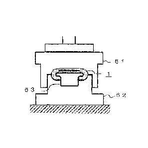
FIG. 6A is a schematic view for illustrating a first step
of the moving handrail manufacturing method according to the
first embodiment of the present invention in partial cross
section.
FIG. 6B is a schematic view for illustrating a second step
of the moving handrail manufacturing method according to the
first embodiment of the present invention in partial cross
section.
FIG. 6C is a schematic view for illustrating a third step
4
Date Recue/Date Received 2020-11-05
CA 03099467 2020-11-05
of the moving handrail manufacturing method according to the
first embodiment of the present invention in partial cross
section.
FIG. 6D is a schematic view for illustrating a fourth step
of the moving handrail manufacturing method according to the
first embodiment of the present invention in partial cross
section.
Description of Embodiments
[0011] Now, description is made of a moving handrail
manufacturing method according to an exemplary embodiment of the
present invention with reference to the drawings.
[0011] First Embodiment
FIG. 1 is a schematic view for illustrating an example of
an escalator device in which a moving handrail 1 manufactured
using a moving handrail manufacturing method according to a first
embodiment of the present invention is arranged. FIG. 2 is a
sectional view for illustrating the moving handrail 1
manufactured using the moving handrail manufacturing method
according to the first embodiment of the present invention and
a guide 5 to which the moving handrail 1 is mounted in cross
section orthogonal to a longitudinal direction.
[0012] As illustrated in FIG. 1, the moving handrail 1 has
an annular shape, and is circulated and moved by being inverted
Date Recue/Date Received 2020-11-05
CA 03099467 2020-11-05
at landings 2 and 3 of the escalator device. Further,
as
illustrated in FIG. 2, the moving handrail 1 includes a main
body portion 10, a tensile body 20, and a cloth 30.
[0013] As
illustrated in FIG. 2, the main body portion 10
of the moving handrail 1 has a C shape in cross section. The
main body portion 10 has a design surface 10a formed on a front
side and a guide surface 10b formed on a back side. The design
surface 10a is a surface to be touched by a user of the escalator
device by hand. The guide surface 10b has the cloth 30 arranged
on a surface thereof and slides along the guide 5 of the
escalator device.
[0014] The main
body portion 10 is mounted to the guide 5
such that the guide surface 10b covers a surface of the guide 5
of the escalator device. The main body portion 10 is formed of
single thermoplastic elastomer such as polyurethane, polystyrene,
or polyolefin elastomer, or thermoplastic elastomer containing
two or more of the single elastomers mixed therein.
[0015] The
tensile body 20 is embedded in the main body
portion 10 along the longitudinal direction of the moving
handrail 1 in order to satisfy the tensile strength and the
bending strength required for the moving handrail 1. The tensile
body 20 is formed of a metal plate or a plurality of steel cables.
[0016] The
cloth 30 is formed of fiber such as cotton or
linen or resin such as polyester such that the friction
coefficient of the surface becomes lower. The
cloth 30 is
6
Date Recue/Date Received 2020-11-05
CA 03099467 2020-11-05
mounted to the guide surface 10b of the main body portion 10 so
as to cover the guide surface 10b. The cloth 30 mounted to the
guide surface 10b is slid relative to the surface of the guide
5.
[0017] Next, a step of molding the moving handrail 1
configured as described above is described. The molding step
for the moving handrail 1 described here is an example, and does
not specify the moving handrail manufacturing method of the
present invention. As the step of molding the moving handrail
1, any of the steps that have hitherto been known may be used.
[0018] First, the tensile body 20 and the cloth 30 are
arranged on an insert line of an extrusion molding machine (not
shown). The tensile body 20 is arranged at a position at which
the tensile body 20 is to be embedded in the thermoplastic
elastomer. The cloth 30 is arranged on a surface on which the
guide surface 10b is to be formed.
[0019] Next, the thermoplastic elastomer is poured into a
mold of the extrusion molding machine, and the main body portion
is subjected to extrusion molding together with the tensile
body 20 and the cloth 30. Next, the endless moving handrail 1
that is continuously formed is wound around a core body for
primary storage while being cooled by a medium such as water or
air.
[0020] Next, the endless moving handrail 1 wound around the
core body for primary storage is cut to a length corresponding
7
Date Recue/Date Received 2020-11-05
CA 03099467 2020-11-05
to the specification of a final product. The cut surface of the
cut moving handrail 1 is similar to the cross section of the
moving handrail 1 illustrated in FIG. 2.
[0021] Next, a step of molding the cut moving handrail 1
into an annular shape is described with reference to FIG. 3.
FIG. 3 is a view for illustrating one end side la and another
end side lb of the processed moving handrail 1. The step of
molding the moving handrail 1 into an annular shape described
here is an example, and does not specify the moving handrail
manufacturing method of the present invention. As the step of
molding the moving handrail 1 into an annular shape, any of the
steps that have hitherto been known may be used.
[0022] First, on the one end side la of the moving handrail
1, the guide surface 10b side of the main body portion 10 is cut
to an intermediate portion in a thickness direction of the
tensile body 20 in a range of the length Li from an end surface
laa of the one end side la toward the another end side lb. Then,
a joining surface lab is formed on the guide surface 10b side of
the one end side la, and a joining surface lac, which is
perpendicular to the longitudinal direction of the moving
handrail 1, is formed on an end portion of the joining surface
lab on the another end side lb.
[0023] Next, on the another end side lb of the moving
handrail 1, the design surface 10a side of the main body portion
is cut to an intermediate portion in the thickness direction
8
Date Recue/Date Received 2020-11-05
CA 03099467 2020-11-05
of the tensile body 20 in a range of the length Li from an end
surface lba of the another end side lb toward the one end side
la. Then, a joining surface lbb is formed on the design surface
10a side of the another end side lb, and a joining surface lbc,
which is perpendicular to the longitudinal direction of the
moving handrail 1, is formed on an end portion of the joining
surface lbb on the one end side la.
[0024] Next, as illustrated in FIG. 3, the joining surface
lab on the one end side la of the moving handrail 1 and the
joining surface lbb on the another end side lb are overlaid on
each other, and the moving handrail 1 is arranged in a mold (not
shown).
[0025] Next, the one end side la and the another end side
lb of the moving handrail 1 in the mold are heated by a heating
device (not shown). Then, the thermoplastic elastomer forming
the end surface laa and the joining surfaces lab and lac on the
one end side la and the end surface lba and the joining surfaces
lbb and lbc on the another end side lb is melted.
[0026] Next, the end surface laa on the one end side la and
the joining surface lbc on the another end side lb, the joining
surface lab on the one end side la and the joining surface lbb
on the another end side lb, and the joining surface lac on the
one end side la and the end surface lba on the another end side
lb are butted against each other and welded to each other,
respectively. A portion in which the one end side la and the
9
Date Recue/Date Received 2020-11-05
CA 03099467 2020-11-05
another end side lb of the moving handrail 1 are welded to each
other is hereinafter referred to as a joining portion 10c.
[0027] Next,
the joining portion 10c of the moving handrail
1 and the mold are cooled under a state in which the moving
handrail 1 is arranged in the mold. Next, the moving handrail
1 is taken out from the mold. Thus, the joining of the one end
side la and the another end side lb of the moving handrail 1 is
completed, thereby forming the moving handrail 1 having an
annular shape. After
that, steps in the moving handrail
manufacturing method according to the first embodiment of the
present invention are performed on the moving handrail 1 having
an annular shape.
[0028] Here,
defects caused in the main body portion 10 of
the moving handrail 1 and the design surface 10a by the related-
art moving handrail manufacturing method are described.
[0029] FIG. 4
is a partial perspective view for illustrating
an example of defects caused in a moving handrail 1 manufactured
without using the moving handrail manufacturing method according
to the first embodiment of the present invention in partial cross
section. FIG. 4 is an illustration of the joining portion 10c
of the moving handrail 1 in a cross section of the another end
side lb cut at a position of the joining surface lac on the one
end side la illustrated in FIG. 3.
[0030] In the
main body portion 10 and the design surface
10a in the joining portion 10c, a cavity 40 and a cavity 41 as
Date Recue/Date Received 2020-11-05
CA 03099467 2020-11-05
illustrated in FIG. 4 may be formed by air bubbles generated
when the thermoplastic elastomer is melted. The moving handrail
1 is subjected to bending stress when the moving handrail 1 is
mounted to the escalator device and is inverted. Therefore,
when the cavity 40 or the cavity 41 is present, a crack may be
formed in the main body portion 10 or the design surface 10a
from the cavity 40 or the cavity 41 as a starting point, with
the result that the moving handrail 1 may be broken.
[0031] Further, when the joining surfaces are welded to
each other and cooled, a sink mark 42 may be formed in the design
surface 10a of the moving handrail 1 as illustrated in FIG. 4.
The cavity 41 and the sink mark 42 formed in the design surface
10a impair the appearance of the moving handrail 1, and hence
the moving handrail 1 is treated as a defective product.
[0032] Further, when the welding between the one end side
la and the another end side lb of the moving handrail 1 is
insufficient in the joining portion 10c, as illustrated in FIG.
4, a gap 43 may be formed between the end surface laa on the one
end side la and the joining surface lbc on the another end side
lb in the joining portion 10c. Such a gap 43 causes breakage of
the moving handrail 1.
[0033] Further, in the guide surface 10b of the moving
handrail 1, the cloth 30 is not in close contact with the guide
surface 10b in some cases. When the cloth 30 is not in close
contact with the guide surface 10b, as illustrated in FIG. 4,
11
Date Recue/Date Received 2020-11-05
CA 03099467 2020-11-05
the cloth 30 may be separated from the guide surface 10b to form
a gap 44. When the gap 44 is formed between the cloth 30 and
the guide surface 10b, there is a fear in that the slidability
between the guide surface 10b and the guide 5 of the escalator
device is lowered, and the cloth 30 peels off from the guide
surface 10b to protrude from the moving handrail 1.
[0034] In order
to correct such defects, the steps in the
moving handrail manufacturing method of the present invention
are performed on the joining portion 10c of the moving handrail
1 and the periphery of the joining portion 10c. The
thermoplastic elastomer is thermoplastic, and hence can be re-
molded by heating and softening. The
moving handrail
manufacturing method of the present invention utilizes such a
property of the thermoplastic elastomer to correct the defects.
[0035] In the
following, a mold 50 to be used in the moving
handrail manufacturing method according to the first embodiment
of the present invention and the steps in the moving handrail
manufacturing method are described.
[0036] First,
the mold 50 to be used in the moving handrail
manufacturing method is described. FIG. 5
is an exploded
perspective view of the mold 50. The mold 50 is formed of three
members including an upper mold 51, a lower mold 52, and a middle
core 53.
[0037] The
upper mold 51 has a shape conforming to the
design surface 10a of the moving handrail 1. The lower mold 52
12
Date Recue/Date Received 2020-11-05
CA 03099467 2020-11-05
has a shape conforming to a surface on a side opposite to the
design surface 10a of the moving handrail 1. Further, the lower
mold 52 has a mounting surface 52a to which the middle core 53
is to be mounted. The middle core 53 has a shape conforming to
the guide surface 10b.
[0038] The dimensions of the upper mold 51 and the lower
mold 52 in the longitudinal direction are all set to the same
length L2. The length L2 of the mold 50 in the longitudinal
direction is set larger than the length Li of the joining portion
10c by, for example, 50 mm or more to both sides so as to cover
the entire part in which defects such as the cavities 40 and 41,
the sink mark 42, and the gaps 43 and 44 due to the welding of
the moving handrail 1 are expected to be caused.
[0039] Both end portions of each of the upper mold 51 and
the lower mold 52 in the longitudinal direction have a tapered
shape expanding toward the outside of the mold 50 so as to
prevent an edge mark of the mold 50 from being formed in the
periphery of the joining portion 10c of the moving handrail 1.
[0040] The length L3 of the middle core 53 is set to be
equal to or larger than the length L2 of the upper mold 51 and
the lower mold 52 in order to stabilize the posture of the moving
handrail 1 in the mold 50. The middle core 53 may be formed by
assembling the plurality of components or formed integrally.
[0041] The mold 50 includes a heating mechanism and a press
mechanism (not shown).
13
Date Recue/Date Received 2020-11-05
CA 03099467 2020-11-05
[0042] The
heating mechanism is, for example, an electric
rod heater to be inserted into at least one of the upper mold 51
and the lower mold 52. The
press mechanism pressurizes the
moving handrail 1 by advancing or retreating at least one of the
upper mold 51 and the lower mold 52 relative to another one of
the upper mold 51 and the lower mold 52.
[0043] In the
moving handrail manufacturing method of the
present invention, the thermoplastic elastomer forming the
periphery of the joining portion 10c of the moving handrail 1 is
heated by the heating mechanism to a temperature equal to or
less than a thermal decomposition temperature and close to a
glass transition temperature, around which temperature the
viscosity appears in the thermoplastic elastomer. Then,
the
moving handrail 1 is pressurized by the mold 50 along the shape
of the moving handrail 1. The thermoplastic elastomer heated to
the temperature around which the viscosity appears is
pressurized so that defects such as the cavities 40 and 41 and
the gap 43 caused in the preceding step can be corrected.
[0044] Further,
the mold 50 includes a cooling mechanism
(not shown).
[0045] The
cooling mechanism is formed by, for example,
providing a flow passage for a refrigerant such as water or air
in at least one of the upper mold 51 and the lower mold 52. The
cooling mechanism lowers the temperature of the heated moving
handrail 1 under a state in which the moving handrail 1 is held
14
Date Recue/Date Received 2020-11-05
CA 03099467 2020-11-05
between the upper mold 51 and the lower mold 52, thereby
stabilizing the shape of the moving handrail 1. With this, the
defects such as the sink mark 42 formed in the design surface
10a of the moving handrail 1 in the preceding step can be
corrected. Further, the cooling mechanism is provided so that
the time required for cooling the moving handrail 1 can be
shortened.
[0046] Next, the steps in the moving handrail manufacturing
method according to the first embodiment using the mold 50 are
described with reference to FIG. 6A to FIG. 6D.
[0047] First, the temperatures of the upper mold 51 and the
lower mold 52 are raised to a temperature close to the glass
transition temperature of the thermoplastic elastomer forming
the moving handrail 1 by the heating mechanism (not shown) of
the mold 50. The temperature of the middle core 53 may be raised
at the same time as the upper mold 51 and the lower mold 52. It
is preferred that the temperature of the middle core 53 be raised
by heat transferred from the upper mold 51 and the lower mold 52
in order to prevent the cloth 30 of the moving handrail 1 from
being burnt.
[0048] Next, as illustrated in FIG. 6A, the middle core 53
is inserted through the guide surface 10b in the joining portion
10c of the joined moving handrail 1. Next, as illustrated in
FIG. 6B, the middle core 53 to which the moving handrail 1 is
Date Recue/Date Received 2020-11-05
CA 03099467 2020-11-05
mounted is arranged on the mounting surface 52a of the lower
mold 52.
[0049] Next, as illustrated in FIG. 6C, the upper mold 51
is moved toward the lower mold 52.
[0050] Next, as illustrated in FIG. 6D, the moving handrail
1 and the middle core 53 are sandwiched by the upper mold 51 and
the lower mold 52 in an up-and-down direction.
[0051] Next, the temperatures of the joining portion 10c of
the moving handrail 1 sandwiched by the upper mold 51 and the
lower mold 52 and the periphery of the joining portion 10c are
raised to the temperature around which the viscosity appears in
the thermoplastic elastomer forming the moving handrail 1. At
this time, a gap is prevented from being formed between each of
the upper mold 51, the middle core 53, and the lower mold 52 and
the moving handrail 1. When a gap is formed, there is a fear in
that an irregular shape is formed in the design surface 10a of
the moving handrail 1.
[0052] When the temperatures of the joining portion 10c of
the moving handrail 1 and the periphery of the joining portion
10c are raised to the temperature around which the viscosity
appears in the thermoplastic elastomer, the upper mold 51 is
further lowered, and the joining portion 10c of the moving
handrail 1 and the periphery of the joining portion 10c are
pressurized. With this, the defects such as the cavities 40 and
41, the sink mark 42, and the gaps 43 and 44 caused in the
16
Date Recue/Date Received 2020-11-05
CA 03099467 2020-11-05
joining portion 10c of the moving handrail 1 and the periphery
of the joining portion 10c can be corrected.
[0053] Next, the upper mold 51, the lower mold 52, the
middle core 53, and the moving handrail 1 are cooled by the
cooling mechanism provided to the mold 50.
[0054] After the joining portion 10c of the moving handrail
1 and the periphery of the joining portion 10c are cooled to a
temperature at which the shape is stabilized, the upper mold 51
is raised to be separated from the lower mold 52. Next, the
middle core 53 to which the moving handrail 1 is mounted is
removed from the lower mold 52. Next, the middle core 53 is
removed from the moving handrail 1. With this, the steps in the
moving handrail manufacturing method according to the first
embodiment are completed.
[0055] In the preceding step of the moving handrail
manufacturing method according to the first embodiment, when
there is a portion in which the thermoplastic elastomer is
insufficient on the surface of the moving handrail 1, it is
preferred that the thermoplastic elastomer be replenished in the
insufficient portion, and then the moving handrail 1 be
pressurized by the upper mold 51 and the lower mold 52 so as to
be molded. Further, when a burr or the like is formed on the
surface of the moving handrail 1 after the molding, it is
preferred that the burr be removed by a cutter or the like.
[0056] As described above, the moving handrail
17
Date Recue/Date Received 2020-11-05
CA 03099467 2020-11-05
manufacturing method according to the first embodiment includes
the step of reheating and pressurizing the joining portion 10c
of the moving handrail 1, which is formed into an annular shape
by joining one end side and another end side of a long composite
material including the cloth 30, the main body portion 10 formed
of the thermoplastic elastomer, and the tensile body 20, and the
periphery of the joining portion 10c. With this, defects such
as the cavity 41, the sink mark 42, and the gap 43 caused in the
design surface 10a of the moving handrail 1 can be corrected.
Further, defects such as the cavity 40 and the gap 44 caused
inside the main body portion 10 of the moving handrail 1 are
corrected so that the durability of the moving handrail 1 can be
improved.
[0057] In the first embodiment, the upper mold 51 of the
mold 50 is moved toward the lower mold 52 to pressurize the
joining portion 10c of the moving handrail 1 and the periphery
of the joining portion 10c. However, the configuration of the
mold 50 is not limited thereto. For example, the lower mold 52
may be moved toward the upper mold 51, or both the upper mold 51
and the lower mold 52 may be moved.
[0058] Second Embodiment
The moving handrail 1 used in the escalator is damaged by
friction with a component that drives the moving handrail 1. In
particular, the joining portion of the moving handrail 1 and the
periphery of the joining portion are less liable to be bent, and
18
Date Recue/Date Received 2020-11-05
CA 03099467 2020-11-05
hence are more liable to be damaged by the friction. Further,
damage such as scratches or scrapes is caused on the surface of
the moving handrail 1 by nails of a user, baggage, and the like.
In the second embodiment, the damaged portion of the moving
handrail 1 is repaired using the moving handrail manufacturing
method similar to that of the first embodiment so that the
defects of the moving handrail 1 are corrected. The
moving
handrail manufacturing method according to the second embodiment
is performed, for example, at the time of maintenance of the
escalator.
[0059] In the
moving handrail manufacturing method
according to the second embodiment, first, the moving handrail
1 is removed from the guide.
Next, the moving handrail 1 to be repaired is set in the
mold 50. When the joining portion of the moving handrail 1 is
damaged, the joining portion and the periphery of the joining
portion are set in the mold 50. When a portion of the moving
handrail 1 other than the joining portion is damaged, the damaged
portion is set at the center of the mold 50.
[0060] The
subsequent steps are similar to the steps in the
moving handrail manufacturing method according to the first
embodiment.
When the surface of the moving handrail 1 is scraped, and
the thermoplastic elastomer is insufficient, the thermoplastic
elastomer is replenished in the insufficient portion, and the
19
Date Recue/Date Received 2020-11-05
CA 03099467 2020-11-05
portion is heated and pressurized.
[0061] As
described above, in the moving handrail
manufacturing method according to the second embodiment, the
damaged portion in the moving handrail 1 used in the escalator
is heated and pressurized so that the damage of the moving
handrail 1 can be repaired.
[0062] The
moving handrail 1 used in the escalator being
operated is deformed with time. With this, the gap between the
moving handrail 1 and the guide 5 becomes larger. As a result,
the force for gripping the guide 5 by the moving handrail 1 is
lowered, and defects such as vibration and abnormal sound are
caused in the moving handrail 1. When the gap between the moving
handrail 1 and the guide 5 further becomes larger, there is a
fear in that the moving handrail 1 comes off from the guide 5.
[0063] The
moving handrail 1 deformed as described above
can be corrected by the moving handrail manufacturing method
according to the second embodiment. That is,
the deformed
portion of the moving handrail 1 is heated using the heating
mechanism of the mold 50. Then, the thermoplastic elastomer of
the moving handrail 1 is softened to be permeated through the
cloth 30. Further, the deformed portion of the moving handrail
1 is pressurized and repaired using the press mechanism of the
mold 50. With this, the force for gripping the guide 5 by the
moving handrail 1 can be restored. Accordingly, the durability
of the moving handrail 1 can be improved to extend the life of
Date Recue/Date Received 2020-11-05
CA 03099467 2020-11-05
the moving handrail 1.
Reference Signs List
[0064] 1 moving
handrail, la one end side, lb another end
side, laa, lba end surface, lab, lac, lbb, lbc joining surface,
2, 3 landing, 5 guide, 10 main body portion, 10a design surface,
10b guide surface, 10c joining portion, 20 tensile body, 30 cloth,
40, 41 cavity, 42 sink mark, 43, 44 gap, 50 mold, 51 upper mold,
52 lower mold, 52a mounting surface, 53 middle core
21
Date Recue/Date Received 2020-11-05