Note : Les descriptions sont présentées dans la langue officielle dans laquelle elles ont été soumises.
CA 03099544 2020-11-05
87433848
FLUID MIXING SYSTEMS AND METHODS
CROSS-REFERENCE TO RELATED APPLICATIONS
Won The present document is based on and claims priority to US Application
Serial
No.: 15/974,309, filed May 08, 2018.
BACKGROUND
[0002] Fluid pipeline systems may include systems for providing samples of
fluid flowing
therein, such as during custody transfer. Accurate sampling of the fluid
flowing through the
pipeline typically requires that the point from which the sample is drawn is
representative of the
average (quality) of the whole cross-section. Thus, sufficient mixing of the
fluid flowing through
the pipeline may allow accurate samples to be taken from a single point of the
cross-section of
the fluid pipeline. In some applications, the pipeline velocity may be
adequate to provide
homogeneity of fluid composition in the fluid flow via natural turbulence.
However, in other
applications, mixing systems may be utilized to improve the homogeneity of the
fluid flow. Fluid
mixing systems for pipeline applications may include static mixers, motor
driven shear mixers,
and jet mixers.
[0003] In-
line or static mixers derive their energy from the fluid flow within the
pipeline, and turbulence is created by dividing and turning the fluid. Energy
added by the static
mixer to the flow for mixing is generally proportional to the square of the
flowrate. Generally,
static mixers add more turbulence to the pipeline fluid flow as the pipeline
flow rate increases.
Thus, static mixers may create insufficient mixing at low pipeline flow rates
and excessive
pressure loss at high pipeline flow rates. Jet mixing systems may include a
pump that provides
an external energy source and a jet or jetting assembly that re-injects fluid
back into the pipeline
as part of a return loop. Unlike static mixers that may have a limited
rangeability (i.e., the ratio
between the maximum and minimum operating flow rates in the pipeline), jet
mixers may offer
improved rangeability by progressively adding more turbulence (measured in
watts/kilogram,
for instance) to the pipeline fluid flow as the pipeline flow rate drops.
1
Date Recue/Date Received 2020-11-05
CA 03099544 2020-11-05
WO 2019/217498 PCT/US2019/031227
SUMMARY
[0004] An embodiment of a jet-mixer for a fluid mixing system comprises a
housing comprising a
mixer port formed in an inner surface of the housing, and a rotor rotatably
disposed in the housing,
the rotor comprising a rotor blade, wherein the rotor comprises a first
angular position in the
housing restricting fluid flow through the mixer port, and a second angular
position allowing fluid
flow through the mixer port, wherein, in response to rotation of the rotor in
the housing, the jet-
mixer is configured to inject a first fluid jet through the mixer port into
the passage of the fluid
conduit that has a pulsed velocity profile In some embodiments, the pulsed
velocity profile
comprises a plurality of velocity cycles, each velocity cycle comprising a
maximum velocity, a
minimum velocity, and a velocity transition extending between the maximum and
minimum
velocities, wherein the maximum velocity is greater than the minimum velocity.
In some
embodiments, the rotor comprises a first surface area that is greater than a
second surface area
comprising an arcuate gap formed in the rotor, and the minimum velocity for
each velocity cycle of
the pulsed velocity profile obtains for a greater period of time than the
maximum velocity for each
velocity cycle. In certain embodiments, the jet-mixer further comprises a
motor coupled to the
rotor, the motor configured to control the rotational speed of the rotor in
the housing and thereby
control a frequency of the velocity cycle of the pulsed velocity profile. In
certain embodiments,
the pulsed velocity profile comprises a sinusoidal velocity profile. In some
embodiments, the mixer
port is defined by a curved inner surface In some embodiments, the mixer port
is defined by a
linear inner surface In certain embodiments, the jet-mixer is configured to
inject a second fluid jet
through the mixer port into the passage of the fluid conduit that has a
constant velocity profile
when the rotor is held in the second angular position.
[0005] An embodiment of a fluid system for use with a fluid conduit comprises
a probe that
extends into a central passage of the fluid conduit through a first port of
the fluid conduit, and a
first conduit coupled between the probe and a jet-mixer and configured to
direct a first fluid flow to
the jet-mixer, wherein the first fluid flow is captured from the passage of
the fluid conduit by the
probe, wherein the jet-mixer is configured to receive the first fluid flow
from the first conduit and
inject a first fluid jet into the passage of the fluid conduit that has a
pulsed velocity profile, the first
fluid jet configured to mix a conduit fluid flow disposed in the passage of
the fluid conduit. In
some embodiments, the jet-mixer comprises a housing comprising a mixer port
formed in an inner
surface of the housing, and a rotor rotatably disposed in the housing, the
rotor comprising a rotor
2
CA 03099544 2020-11-05
87433848
blade, wherein the rotor comprises a first angular position in the housing
restricting fluid flow
through the mixer port, and a second angular position allowing fluid flow
through the mixer port.
In some embodiments, the jet-mixer is configured to inject the first fluid jet
through the mixer
port into the passage of the fluid conduit in response to rotation of the
rotor in the housing, and
the jet-mixer is configured to inject a second fluid jet through the mixer
port into the passage of
the fluid conduit that has a constant velocity profile when the rotor is held
in the second angular
position. In certain embodiments, the fluid system further comprises a fluid
energizer coupled
between the first conduit and the jet-mixer, wherein the fluid energizer is
configured to energize
the first fluid flow. In certain embodiments, the fluid energizer comprises a
pump configured to
pressurize the first fluid flow. In some embodiments, the pump is configured
to increase fluid
pressure in the housing of the jet-mixer when the rotor of the jet-mixer is
disposed in the first
angular position. In some embodiments, the fluid system further comprises a
motor coupled to
the rotor of the jet-mixer, the motor configured to control the rotational
speed of the rotor in the
housing. In some embodiments, the fluid system further comprises a fluid
sampler coupled to the
first fluid conduit and configured to capture a fluid sample from the first
fluid flow.
100061 An embodiment of a method for mixing a fluid flow in a fluid conduit
comprises providing
a first fluid flow to a jet-mixer from a passage of the fluid conduit, and
injecting a fluid jet through
a mixer port of the jet-mixer into the passage of the fluid conduit, the fluid
jet having a pulsed
velocity profile. In some embodiments, the method further comprises increasing
a rotational
speed of a rotor of the jet-mixer to thereby increase a frequency of a
velocity cycle of the pulsed
velocity profile, the velocity cycle comprising a maximum velocity and a
minimum velocity. In
some embodiments, the method further comprises pressurizing the first fluid
flow provided to the
jet-mixer using a pump. In certain embodiments, the method further comprises
increasing an
output pressure of the pump to thereby increase the energy imparted to fluid
in the fluid conduit
from the fluid jet.
[0006a] According to one aspect of the present invention, there is provided a
jet-mixer for a fluid
mixing system, comprising: a housing comprising a mixer port formed in an
inner surface of the
housing; and a rotor rotatably disposed in the housing, the rotor comprising a
rotor blade; wherein
the rotor comprises a first angular position in the housing restricting fluid
flow through the mixer
port, and a second angular position allowing fluid flow through the mixer
port; wherein, in
3
Date Recue/Date Received 2020-11-05
CA 03099544 2020-11-05
87433848
response to rotation of the rotor in the housing, the jet-mixer is configured
to inject a first fluid jet
through the mixer port into a passage of a fluid conduit that has a pulsed
velocity profile.
[0006b] According to another aspect of the present invention, there is
provided a fluid system for
use with a fluid conduit, comprising: a probe that extends into a central
passage of the fluid
conduit through a first port of the fluid conduit; and a first conduit coupled
between the probe and
a jet-mixer and configured to direct a first fluid flow to the jet-mixer,
wherein the first fluid flow
is captured from the passage of the fluid conduit by the probe; wherein the
jet-mixer is configured
to receive the first fluid flow from the first conduit and inject a first
fluid jet into the passage of
the fluid conduit that has a pulsed velocity profile, the first fluid jet
configured to mix a conduit
fluid flow disposed in the passage of the fluid conduit.
[0006c] According to another aspect of the present invention, there is
provided a method for
mixing a fluid flow in a fluid conduit, comprising: providing a first fluid
flow to a j et-mixer from
a passage of the fluid conduit; and injecting a fluid jet through a mixer port
of the jet-mixer into
the passage of the fluid conduit, the fluid jet having a pulsed velocity
profile.
BRIEF DESCRIPTION OF THE DRAWINGS
[0007] For a detailed description of exemplary embodiments, reference will now
be made to the
accompanying drawings in which:
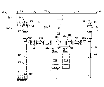
[0008] Figure 1 is a schematic view of embodiments of a fluid mixing system
and a fluid
sampling system for use with a pipeline in accordance with principles
disclosed herein;
3a
Date Recue/Date Received 2020-11-05
CA 03099544 2020-11-05
WO 2019/217498 PCT/US2019/031227
[0009] Figure 2 is a cross-sectional view along line 2-2 of Figure 1 of the
pipeline of Figure 1;
[0010] Figure 3 is a first cross-sectional view of an embodiment of a jet-
mixer of the fluid mixing
system of Figure 1 in accordance with principles disclosed herein;
[00111 Figure 4 is a second cross-sectional view of the jet-mixer of Figure 3;
[0012] Figure 5 is a graph depicting an embodiment of a first velocity profile
of the jet-mixer of
Figure 3 in accordance with principles disclosed herein;
[0013] Figure 6 is a graph depicting an embodiment of a second velocity
profile of the jet-mixer of
Figure 3 in accordance with principles disclosed herein,
[0014] Figure 7 is a cross-sectional view of another embodiment of a jet-mixer
of the fluid mixing
system of Figure 1 in accordance with principles disclosed herein;
[0015] Figure 8 is a graph depicting an embodiment of a velocity profile of
the jet-mixer of Figure
7 in accordance with principles disclosed herein;
100161 Figure 9 is a cross-sectional view of another embodiment of a jet-mixer
of the fluid mixing
system of Figure 1 in accordance with principles disclosed herein;
[0017] Figure 10 is a graph depicting an embodiment of a velocity profile of
the jet-mixer of
Figure 9 in accordance with principles disclosed herein; and
[0018] Figure 11 is a flowchart depicting an embodiment of a method for mixing
a fluid flow in a
fluid conduit in accordance with principles disclosed herein.
DETAILED DESCRIPTION
[0019] In the drawings and description that follow, like parts are typically
marked throughout the
specification and drawings with the same reference numerals. The drawing
figures are not
necessarily to scale. Certain features of the disclosed embodiments may be
shown exaggerated in
scale or in somewhat schematic form and some details of conventional elements
may not be shown
in the interest of clarity and conciseness. The present disclosure is
susceptible to embodiments of
different forms. Specific embodiments are described in detail and are shown in
the drawings, with
the understanding that the present disclosure is to be considered an
exemplification of the principles
of the disclosure, and is not intended to limit the disclosure to that
illustrated and described herein.
It is to be fully recognized that the different teachings of the embodiments
discussed below may be
employed separately or in any suitable combination to produce desired results.
4
CA 03099544 2020-11-05
87433848
100201 Unless otherwise specified, in the following discussion the terms
"including" and
"comprising" are used in an open-ended fashion, and thus should be interpreted
to mean
"including, but not limited to ...". Any use of any form of the terms
"connect", "engage",
"couple", "attach", or any other term describing an interaction between
elements is not meant to
limit the interaction to direct interaction between the elements and may also
include indirect
interaction between the elements described. The various characteristics
mentioned above, as well
as other features and characteristics described in more detail below, will be
readily apparent to
those skilled in the art upon reading the following detailed description of
the embodiments, and
by referring to the accompanying drawings.
100211 Referring to Figure 1, an embodiment of a fluid mixing system 100 for
use with a fluid
conduit or pipeline 10 is shown. Fluid pipeline 10 is generally configured to
facilitate the transport
of a fluid flowing (indicated by arrow 5 in Figure 1) therein. In the
embodiment of Figure 1, fluid
mixing system 100 is generally configured to mix the contents of pipeline
fluid flow 5 within
fluid pipeline 10 to provide a substantially homogenous mixture therein for
sampling by a fluid
sampling system 200. Thus, in this embodiment, fluid mixing system 100 allows
fluid sampling
system 200 to capture a representative sample of the fluid comprising pipeline
fluid flow 5, where
pipeline fluid flow 5 comprises a first fluid and at least one additional or
second fluid that has one
or more properties (e.g., density, viscosity, etc.) that vary from properties
of the first fluid. In the
embodiment of Figure 1, pipeline fluid flow 5 comprises hydrocarbons and
water; however, in
other embodiments, pipeline fluid flow 5 may comprise varying mixtures of a
number of different
fluids, including immiscible and/or miscible fluids.
100221 In some embodiments, fluid sampling system 200 of fluid mixing system
100 may be used
in custody-transfer, allocation, and quality measurement applications. Thus,
in at least some
embodiments, the performance of sampling system 200 is dependent upon
capturing a
substantially homogenous or representative mixture of the different fluids
comprising pipeline
fluid flow 5, with mixing system 100 serving to increase the homogeneity and
representativeness
of the fluid sample captured from pipeline fluid flow 5 by sampling system
200. However,
although the embodiment of fluid mixing system 100 shown in Figure 1 includes
fluid sampling
system 200, in other embodiments, fluid mixing system 100 may not include a
sampling system.
Moreover, in other embodiments, fluid mixing system 100 may be used in
conjunction with fluid
systems other than fluid pipelines.
Date Recue/Date Received 2020-11-05
CA 03099544 2020-11-05
WO 2019/217498 PCT/US2019/031227
[0023] In the embodiment of Figure 1, fluid pipeline 10 has a central or
longitudinal axis 15 and
includes a central bore or passage 12, an upper end or top 14, and a lower end
or bottom 16.
Specifically, the top 14 of pipeline 10 is disposed above bottom 16 relative
to the surface of the
Earth such that gravity applies a force to the fluid comprising pipeline fluid
flow 5 in the direction
of bottom 16. In the embodiment of Figure 1, pipeline 10 includes a first or
upstream port 18 and a
second or downstream port 20 axially spaced from upstream port 18 and located
downstream of
port 18 respective the direction of pipeline fluid flow 5. Each port 18, 20,
extends radially through
a generally cylindrical wall 28 of pipeline 10 that defines central passage 12
to provide fluid
communication between ports 18, 20, and passage 12. In this configuration,
pipeline 10 includes a
first or upstream zone 22 extending upstream from upstream port 18, a second
or downstream zone
24 extending downstream from downstream port 20, and a third or mixing zone 26
extending
axially between ports 18 and 20.
100241 In the embodiment of Figure 1, fluid mixing system 100 generally
includes a fluid
extraction probe 102, a suction valve 104, a fluid first or suction conduit
106, a fluid energizer or
pump 108 powered by a power or energy source 110, a fluid second or discharge
conduit 112, a
discharge valve 114, and a mixing assembly or jet-mixer 150. Probe 102 of
mixing system 100
extends through downstream port 20 into central passage 12 of pipeline 10.
Probe 102 includes a
fluid inlet 103 that receives or captures fluid from pipeline fluid flow 5 for
passage into suction
conduit 106 as a fluid mixing flow (indicated by arrow 105 in Figure 1). In
the embodiment of
Figure 1, fluid inlet 103 of probe 102 is positioned towards the bottom 16 of
pipeline 10 (e.g.,
between central axis 15 and bottom 16); however, in other embodiments, fluid
inlet 103 may be
positioned along central axis 15 or towards the top 14 of pipeline 10 (e.g.,
between central axis 15
and top 14). Additionally, in the embodiment of Figure 1, probe 102 is
disposed orthogonal central
axis 15 of pipeline 10 such that a central axis of probe 102 intersects
central axis 15; however, in
other embodiments, probe 102 may be radially offset from central axis 15 of
pipeline 10.
[0025] Suction conduit 106 of fluid mixing system 100 directs the mixer fluid
flow 105 from the
fluid inlet 103 of probe 102 into a suction of pump 108. In this embodiment,
suction valve 104
allows for the selective isolation of discharge conduit 106 from the central
passage 12 of pipeline
10. Pump 108 is generally configured to energize mixer fluid flow 105 as it
enters the suction
thereof and discharge an energized mixer fluid flow 105 to the discharge
conduit 112. In the
embodiment of Figure 1, pump 108 is configured to increase the fluid pressure
of mixer fluid flow
6
CA 03099544 2020-11-05
WO 2019/217498 PCT/US2019/031227
105 prior to being injected into passage 12 of pipeline 10 via jet-mixer 150.
Although pump 108 is
shown in Figure 1 as comprising a rotary pump powered by an electric motor
110, in other
embodiments, other mechanisms may be used to energize mixer fluid flow 105
prior to injection
into passage 12 of pipeline 10. In still other embodiments, fluid mixing
system 100 may not
include pump 108 or any other externally powered fluid energizer, and instead,
may rely on the
fluid pressure of pipeline fluid flow 5 for supplying sufficient fluid
pressure to jet-mixer 150.
[0026] As described above, fluid sampling system 200 is generally configured
to capture a
representative sample of the fluid comprising pipeline fluid flow 5. In the
embodiment of Figure 1,
sampling system 200 generally includes a sampling conduit 202 configured to
transport a sampling
fluid flow (indicated by arrows 205 in Figure 1), a first or upstream sampling
valve 204, a
sampling flow indicator 206, a fluid sampler 208, a second or downstream
sampling valve 210, a
receiver conduit 212, and a pair of sample receivers or sample storage units
214. Sampling fluid
flow 205 flows into sampling conduit 202 from discharge conduit 112 and flows
out of sampling
conduit 202 into suction conduit 106. In this embodiment, sampling valves 204
and 210 allow for
the selective isolation of sampling system 200 from fluid mixing system 100.
[0027] Flow indicator 206 indicates the flow rate of sampling fluid flow 205
while fluid sampler
208 is configured to capture a fluid sample from sampling fluid flow 205 via
storage units 214. In
the embodiment of Figure 1, fluid sampler 208 comprises a flow-through cell
sampler configured
to discharge a predetermined volume of sampled fluid from sampling fluid flow
205 to receiver
conduit 212 and storage units 214. As discussed above, fluid sampling system
200 may be used in
custody-transfer, allocation, and quality measurement applications. In at
least some applications,
the performance of fluid sampling system 200 is dependent upon the fluid
composition of sampling
fluid flow 205 comprising a representative sample of the fluid composition of
pipeline fluid flow 5.
However, in some applications, pipeline fluid flow 5 may comprise a plurality
of fluids that may
not provide a representative sample for fluid sampler 208 if not mixed by
fluid mixing system 100.
Additionally, in some applications, the flow rate of pipeline fluid flow 5 may
vary over time, and
thus, may comprise a relatively flow rate not conducive for natural mixing of
the fluid elements of
pipeline fluid flow 5. Thus, fluid mixing system 100 is configured to energize
pipeline fluid flow 5
to provide a relatively homogenous mixture of the fluid elements of pipeline
fluid flow 5 to probe
102, where the fluid received by probe 102 is subsequently provided to fluid
sampler 208 via fluid
sampling flow 205. Additionally, in some embodiments, fluid mixing system 100
is configured to
7
CA 03099544 2020-11-05
WO 2019/217498 PCT/US2019/031227
adapt to changing conditions of pipeline fluid flow 5, such as changes in
fluid composition, flow
rate, turbulence, etc., to ensure a relatively homogenous mixture generally
representative of the
fluid composition of pipeline fluid flow 5 is provided to fluid sampler 208 of
sampling system 200.
[0028] Referring to Figures 1-6, jet-mixer 150 of mixing assembly 100 is
generally configured to
inject mixer fluid flow 105 into the central passage 12 of pipeline 10 to
thereby break-up large
globules of a second fluid dispersed in a first fluid of pipeline fluid flow 5
into smaller droplets
and/or distribute the droplets of the second fluid more evenly across the
cross-section of passage
12. In the embodiment of Figures 1-6, the second fluid of pipeline fluid flow
5 comprises water
while the first fluid comprises hydrocarbons. Particularly, jet-mixer 150 is
configured to inject
mixer fluid flow 105 into central passage 12 of pipeline 10 as one or more
jets of fluid, where jet-
mixer 150 is further configured in this embodiment to control or adjust the
velocity of the jets of
mixer fluid flow 105 injected into passage 12. In the embodiment of Figures 1-
6, jet-mixer 150
extends into passage 12 via upstream port 18, and thus, is positioned in
passage 12 upstream from
probe 102. Additionally, in the embodiment of Figures 1-6, discharge valve 114
is positioned
between a terminal end of discharge conduit 112 and jet-mixer 150 to allow for
the selective
isolation of passage 12 of pipeline 10 from discharge conduit 112.
[0029] As shown particularly in Figure 2, in the embodiment of Figures 1-6,
jet-mixer 150
includes an outer housing 152 and a plurality of circumferentially spaced
mixer ports or jets 154,
with jets 154 being disposed within central passage 12 of pipeline 10. In this
embodiment, jets 154
are positioned proximal the bottom 16 of pipeline 10 and tangential to
pipeline fluid flow 5
(directed into the page in Figure 2). In this configuration, jet-mixer 150 is
configured to translate
mixer fluid flow 105 into a pair of mixing helical fluid flows or fluid jets
151 that flow tangential
to the direction of pipeline fluid flow 151, where each helical fluid flow 151
is emitted from a
corresponding jet 154 of jet-mixer 150. In this manner, helical fluid flows
151 break-up large
water droplets of pipeline fluid flow 5 into smaller droplets and assist in
rotating the fluid contents
comprising pipeline fluid flow 5. Although in the embodiment of Figures 1-6
jet-mixer 150 is
shown as comprising a pair of jets 154 circumferentially spaced approximately
180 apart; in other
embodiments, jets 154 may be spaced at varying angles (e.g., spaced 120
apart, etc.).
Additionally, in other embodiments, the housing 152 of jet-mixer 150 may
comprise a varying
number ofjets, including axially spaced jets.
8
CA 03099544 2020-11-05
WO 2019/217498 PCT/US2019/031227
[0030] As mentioned above, jet-mixer 150 is configured to control or adjust
the velocity of helical
fluid flows 151. As shown particularly in Figures 3 and 4, in the embodiment
of Figures 1-6, jet-
mixer 150 additionally includes a rotor 156 (shown in Figure 4) rotatably
disposed in housing 152.
Particularly, jet-mixer 150 has a central or longitudinal axis 155 (shown in
Figures 3 and 4)
extending through housing 152 and rotor 156, where rotor 156 is configured to
rotate bout central
axis 155. In the embodiment of Figure 4, rotor 156 comprises four
circumferentially spaced blades
158 each extending radially between central axis 155 and a generally
cylindrical inner surface 153
of housing 152. In this arrangement, housing 152 comprises a stator 152 with
rotor 156 rotatably
disposed therein.
[0031] In the embodiment of Figure 4, rotor 156 is driven in rotation within
housing 152 by a
motor 160 (shown schematically in Figure 4); however, in other embodiments,
the rotation of rotor
156 within housing 152 may be driven by the fluid pressure of mixer fluid flow
105. As rotor 156
rotates within housing 152 via motor 160, blades 158 of rotor 156 cyclically
block or restrict mixer
fluid flow 105 from entering jets 154. For instance, an arcuate gap 162 formed
in rotor 156
extends circumferentially between radially extending edges 159 of each
adjacently positioned
blade 158 of rotor 156. When jets 154 are in an unblocked position disposed
entirely within gaps
162, mixer fluid flow 105 is unrestricted from entering jets 154 of jet-mixer
150 and central
passage 12 of pipeline 10. The unblocked position of jets 154 corresponds with
a first angular
position of rotor 156 in housing 152 of jet-mixer 150. However, when jets 154
are in a blocked
position disposed entirely between radial edges 159 of blades 158, fluid
communication is
prevented between mixer fluid flow 105 and central passage 12 of pipeline 10,
or in other words,
blades 158 prevent or restrict mixer fluid flow 105 from entering jets 154.
The blocked position of
jets 154 corresponds with a second angular position of rotor 156 in housing
152 that is angularly
spaced from the first angular position. Additionally, in the embodiment of
Figures 3 and 4, blades
158 of rotor 156 may partially overlap jets 154 (shown in Figure 4) in a
partially blocked position
to thereby partially restrict or occlude mixer fluid flow 105 from entering
jets 105, and in-turn,
passage 12 of pipeline 10. The partially blocked position of jets 154
corresponds with a third
angular position of rotor 156 in housing 152 that is disposed angularly
between the first and second
angular positions of rotor 156.
[0032] Figure 5 illustrates a first or constant velocity profile 180 (velocity
amplitude indicated on
the Y-axis and time indicated on the X-axis) of helical fluid flows 151
emitted from jets 154 with
9
CA 03099544 2020-11-05
WO 2019/217498 PCT/US2019/031227
rotor 156 of jet-mixer 150 stationary (not rotating about central axis 155)
and jets 154 in the
unblocked position. In this arrangement, helical fluid flows 151 are emitted
from jets 154 at a
constant velocity, and thus, imparts a constant amount of energy to the fluid
comprising pipeline
fluid flow 5 assuming a constant flow rate of pipeline fluid flow 5 Figure 6
illustrates a second or
sinusoidal velocity profile 190 of helical fluid flows 151 of the jet-mixer
150 while rotor 156
rotates within housing 152 about central axis 155 at a fixed or constant
rotational speed. In the
embodiment of Figure 6, velocity profile 190 comprises a plurality of
cyclically-repeating velocity
peaks 192 corresponding to an unblocked position of jets 154, a plurality of
cyclically-repeating
velocity valleys or stoppages 194 corresponding to the blocked position of
jets 154, and a plurality
of cyclically-repeating velocity ramps or transitions 196 corresponding to the
partially blocked
position of jets 154, where velocity transitions 196 extend temporally between
each adjacent
velocity peak 192 and stoppage 194.
100331 In the embodiment of Figure 6, sinusoidal velocity profile 190
comprises a sin wave with
velocity peaks 192 that have twice the amplitude of the constant velocity
amplitude provided by
constant velocity profile 180 of Figure 5, and stoppages 194 having a velocity
at or near zero. In
other embodiments, stoppages 194 of sinusoidal velocity profile 190 may
comprise a minimal but
non-zero fluid velocity such that the sinusoidal velocity profile 190 always
provides a fluid
velocity greater than zero (e.g., sinusoidal velocity profile 190 may be
shifted upwards such that
stoppages 194 are above zero) Not intending to be bound by any theory, the
increased amplitude
of the velocity peaks 192 of sinusoidal velocity profile 190 relative to the
velocity provided by
constant velocity profile 180 results from increased fluid pressure within
housing 152 of jet-mixer
150 when jets 154 are blocked by the blades 158 of rotor 156. Thus, in the
blocked position, pump
108 of mixing system 100 acts to increase the pressure of mixer fluid flow 105
discharged
therefrom as helical fluid flows 151 when jets 154 are in the blocked
position, thereby increasing
the velocity of helical fluid flows 151 when jets 154 become unblocked.
[0034] As shown in Figures 5 and 6, although the sinusoidal velocity profile
190 varies in velocity
overtime, it comprises the same average velocity as constant velocity profile
180 (a velocity
amplitude of 1.0 in the embodiment of Figures 5 and 6). However, while not
intending to be
bound by any theory, the amount of energy provided to pipeline fluid flow 5
from the helical fluid
flows 151 exiting jets 154 of jet-mixer 150 varies with the cube of the
velocity of helical fluid
flows 151. Thus, velocity peaks 192 of sinusoidal velocity profile 190, having
twice the velocity
CA 03099544 2020-11-05
WO 2019/217498 PCT/US2019/031227
amplitude as the constant amplitude of constant velocity profile 180, provide
eight times the
energy to pipeline fluid flow 5. In-turn, although sinusoidal velocity profile
190 has the same
average velocity amplitude over time as constant velocity profile 180,
provides a greater average
amount of energy over time (2.5 times more energy in this embodiment) to the
fluid of pipeline
fluid flow 5 from helical fluid flows 151. The increased average energy
inputted to pipeline fluid
flow 5 via sinusoidal velocity profile 190 thereby increases the degree of
mixing of the contents of
fluid flow 5 (water and hydrocarbons in the embodiment of Figures 1-6) to
provide a relatively
more homogenous mixture of the fluid components comprising pipeline fluid flow
5 (e.g., water
and hydrocarbons) than the mixture provided by constant velocity profile 180.
Moreover,
sinusoidal velocity profile 190 provides enhancing mixing of pipeline fluid
flow 5 without
requiring additional external power to be supplied to pump 108 from electric
motor 110.
100351 In the embodiment of Figures 1-6, sinusoidal velocity profile 190 of
Figure 6 is at least
partially foiined or defined by the shape of blades 158 of rotor 156, the
shape of jets 154 of
housing 152, and the rotational speed of rotor 156. For instance, the
frequency of sinusoidal
velocity profile 190 (e.g., the number of velocity peaks 192 provided in a
fixed period of time) may
be increased by increasing the rotational speed of rotor 156 and decreased by
decreasing the
rotational speed of rotor 156. In some embodiments, the rotational speed of
rotor 156 may be
adjusted via motor 160 to account for changes in pipeline fluid flow 5. For
instance, a reduction in
the flow rate of pipeline fluid flow 5 may require additional energy to be
inputted to fluid flow 5
from helical fluid flows 151 of mixing system 100 to achieve satisfactory
mixing of the
components of pipeline fluid flow 5 Thus, in response to a decrease in the
flow rate of pipeline
fluid flow 5, motor 160 may be configured (via, e.g., a flow sensor and
accompanying controller,
etc.) to increase the rotational speed of rotor 156 of jet-mixer 150 to ensure
adequate mixing of the
contents of pipeline fluid flow 5. Conversely, motor 160 may be configured to
reduce the
rotational speed of rotor 156 in response to an increase in the flow rate of
pipeline fluid flow 5 to
conserve power or energy consumed by fluid mixing system 100.
100361 Additionally, the velocity profile of helical fluid flows 151 is at
least partially formed or
defined by the shape of blades 158 of rotor 156, and the shape of jets 154 of
housing 152. For
instance, in the embodiment of Figures 1-6, each jet 154 of the housing 152
are defined by a
curved or oval shaped inner surface 157 while the radial edges 159 of blades
158 are linear or
rectilinear in shape. In this arrangement, with rotor 156 rotating within
housing 152, the surface
11
CA 03099544 2020-11-05
WO 2019/217498 PCT/US2019/031227
area of jets 154 is gradually reduced as radial edges 159 of rotor blades 158
gradually sweep over
and block or obstruct jets 154 (shown in Figure 4). The gradual reduction in
unblocked or
unobstructed surface area of jets 154 accounts for the gradual reduction in
velocity amplitude of
velocity transitions 196 shown in Figure 6. Similarly, as rotor blades 158
rotate about central axis
155 in housing 152, the surface area of jets 154 are gradually uncovered or
unblocked by blades
158, producing the gradual or curved increase in velocity amplitude of
velocity transitions 196
Thus, by altering either the shape of jets 154 and/or edges 159 of blades 158,
the shape of the
velocity profile of helical fluid flows 151 may be altered.
[0037] For instance, referring to Figures 7 and 8, another embodiment of a jet-
mixer 300
configured to provide helical fluid flows having a third or clipped sin wave
velocity profile 330 is
shown. Similar to jet-mixer 150 shown in Figures 3 and 4, jet-mixer 300
comprises an outer
housing or stator 302, a plurality of ports or jets 304 formed in housing 302,
and a rotor 306
rotatably disposed in housing 302 and comprising a plurality of
circumferentially spaced rotor
blades 308. However, unlike the curved inner surface 157 of the jets 154 of
jet-mixer 150 shown
in Figures 3 and 4, jets 304 of jet-mixer 300 are each defined by a generally
rectangular inner
surface 307 that corresponds with or matches the linear or rectilinear radial
edges 309 of rotor
blades 308. Similar to jet-mixer 150, arcuate gaps 310 extend
circumferentially between each
adjacently disposed pair of radial edges 309 of the rotor blades 308 of jet-
mixer 300. As shown
particularly in Figure 8, clipped velocity profile 330 comprises a plurality
of cyclically-repeating
velocity peaks 332 corresponding to an unblocked position of jets 304, a
plurality of cyclically-
repeating velocity valleys or stoppages 334 corresponding to the blocked
position of j ets 304, and a
plurality of cyclically-repeating velocity ramps or transitions 336
corresponding to the partially
blocked position of jets 304, where velocity transitions 336 extend temporally
between each
adjacent velocity peak 332 and stoppage 334. In some embodiments, stoppages
334 of clipped
velocity profile 330 may comprise a minimal but non-zero fluid velocity such
that the clipped
velocity profile 330 always provides a fluid velocity greater than zero (e.g.,
clipped velocity profile
330 may be shifted upwards such that stoppages 334 are above zero). In such an
embodiment,
rotor blades 308 and jets 304 may be configured such that at least one jet 304
is always at least
partially unblocked.
[0038] In the embodiment of Figures 8 and 9, velocity transitions 336 of
clipped velocity profile
330 are more linear or square and less curved or sinusoidal than the velocity
transitions 196 of
12
CA 03099544 2020-11-05
WO 2019/217498 PCT/US2019/031227
sinusoidal velocity profile 190 shown in Figure 6. Thus, for a given cycle
(e.g., the time period
between the midpoint of adjacent velocity peaks 332) of clipped velocity
profile 330, a greater
portion of the time duration of the cycle of profile 330 comprises velocity
peak 332 and stoppage
334 relative to each cycle of sinusoidal velocity profile 190 In other words,
velocity transitions
336 of clipped velocity profile 330 are more rapid or abrupt at a given
rotational speed of rotor 306
relative to sinusoidal velocity profile 190. In this manner, the variance in
velocity amplitude over
time of clipped velocity profile 330 is greater than the variance in velocity
amplitude in either
sinusoidal velocity profile 190 of Figure 6 or constant velocity profile 180
of Figure 5.
[0039] Given that clipped velocity profile 330 has a greater variance in
velocity amplitude and
spends a greater portion of time per cycle at velocity peak 332, clipped
velocity profile 330
provides or injects a relatively greater amount of energy over time (at a
given rotational speed of
the rotor of the jet-mixer, and at a given flow rate of pipeline fluid flow 5)
into pipeline fluid flow
(via helical fluid flows extending from jets 304 of j et-mixer 300) than
sinusoidal velocity profile
190. Thus, in some applications, such as low-flow applications or applications
requiring a greater
degree of mixing or agitation to achieve a relatively homogenous mixture of
the contents of
pipeline fluid flow 5, the clipped velocity profile 330 of jet-mixer 300 may
be used to provide a
relatively greater degree of mixing of the contents of pipeline fluid flow 5.
[0040] Beyond varying the rotational speed of the rotor (e.g., rotors 156,
304) of the jet-mixer
(e.g., jet-mixers 150, 300) and varying the geometry of either the jets (e.g.,
jets 154, 304) and/or
radial edges (e.g., radial edges 159, 309) of the rotor blades (e.g., rotor
blades 158, 308) of the j et-
mixer, variations in the velocity profile provided by the jet-mixer may also
be achieved by varying
the ratio in surface area between the rotor blades and the arcuate gaps (e.g.,
arcuate gaps 162, 310)
extending between each adjacently disposed pair of rotor blades. For instance,
referring to Figures
9 and 10, another embodiment of a jet-mixer 350 configured to provide helical
fluid flows having a
fourth or high-amplitude velocity profile 380 is shown. Similar to jet-mixer
300 shown in Figure
7, jet-mixer 350 comprises an outer housing or stator 352, a plurality of
ports or jets 354 formed in
housing 352, and a rotor 356 rotatably disposed in housing 352 and comprising
a plurality of
circumferentially spaced rotor blades 358. However, unlike rotor 306 of jet-
mixer 300 which
includes four rotor blades 308, rotor 356 includes a pair of rotor blades 358.
Each rotor blade 358
includes a pair of radially extending edges 360, with a pair of
circumferentially spaced, arcuate
gaps 362 extending between the pair of rotor blades 358.
13
CA 03099544 2020-11-05
WO 2019/217498 PCT/US2019/031227
[0041] In the embodiment of Figures 9 and 10, each rotor blade 358 has a
surface area 358A
generally defined by a radial length or distance between a radial inner end of
blade 358 located
proximal a central or longitudinal axis 355 of jet-mixer 350 and a radial
outer end of blade 358
located proximal an inner cylindrical surface 353 of housing 352, and an
arcuate length or distance
between the pair of radial edges 360. Similarly, each arcuate gap 362 formed
between rotor blades
358 has a surface area 362A generally defined a radial length or distance
between a radial inner
end of gap 362 located proximal central axis 355 and a radial outer end of gap
362 defined by inner
surface 353, and an arcuate length or distance between the pair of radial
edges 360 defining gap
362. Additionally, rotor 356 has a surface area 356A that generally
corresponds to the sum of the
surface area 358A of each rotor blade 358. In the embodiment of Figures 9 and
10, the surface
area 356A is greater than the combined surface areas 362A of arcuate gaps 362.
In other words,
with each rotation of rotor 356 in housing 352, jets 354 of jet-mixer are
disposed in the blocked
position for a greater amount of time than the unblocked position.
[0042] As shown particularly in Figure 10, high-amplitude velocity profile 380
comprises a
plurality of cyclically-repeating velocity peaks 382 corresponding to an
unblocked position of jets
354, a plurality of cyclically-repeating velocity valleys or stoppages 384
corresponding to the
blocked position of jets 354, and a plurality of cyclically-repeating velocity
ramps or transitions
386 corresponding to the partially blocked position of jets 354, where
velocity transitions 386
extend temporally between each adjacent velocity peak 382 and stoppage 384
Unlike the clipped
velocity profile 330 shown in Figure 8, velocity peaks 382 extend for a
relatively shorter duration
than stoppages 384 per cycle (e.g., the time period between the midpoint of
adjacent velocity peaks
382). For instance, in an embodiment where each cycle of velocity profile
comprises 1.0 second,
each stoppage 384 may continue for 0.6 while each corresponding velocity peak
382 may extend
for 0.3 seconds. The increased temporal duration of each stoppage 384 relative
each velocity peak
382 results from the relatively greater surface area 356A of rotor 356 than
the combined surface
areas 362A of arcuate gaps 362.
100431 Further, due to the temporal imbalance described above with respect to
stoppages 384 and
velocity peaks 382 of high-amplitude velocity profile 380, the velocity
amplitude is increased
(shown as 4.0 in the embodiment of Figure 10 relative to the 1.0 amplitude of
constant velocity
profile 180 of Figure 5) relative to the velocity amplitude of the velocity
peaks 332 (shown as 2.0
in the embodiment of Figure 10 relative to the 1.0 amplitude of constant
velocity profile 180 of
14
CA 03099544 2020-11-05
WO 2019/217498 PCT/US2019/031227
Figure 5) of clipped velocity profile 330. The relative increase in velocity
amplitude of velocity
peaks 382 results from increased fluid pressure buildup within housing 352
from mixer fluid flow
105 that occurs during stoppages 384. Particularly, during each stoppage 384
of high-amplitude
velocity profile 380, pump 380 continues to energize or pressurize the fluid
of mixer fluid flow 105
disposed in discharge conduit 106 and housing 352 of j et-mixer 350. Given
that each stoppage 384
continues for a relatively greater amount of time per cycle of high-amplitude
velocity profile 380
relative to each stoppage 334 of clipped velocity profile 330, pump 108
pressurizes the fluid of
mixer fluid flow 105 to a relatively greater degree, resulting in the
relatively increased velocity
amplitude of each velocity peak 382. An output pressure or pump rate of pump
108 may be
controlled or modulated to control the amount of energy imparted to the
pipeline fluid flow 5 from
jets 354. Moreover, due to the increase in velocity amplitude of velocity
peaks 382, high-
amplitude velocity profile 380 provides relatively more energy to pipeline
fluid flow 105 (via
helical fluid flows from jets 354) per cycle than clipped velocity profile
330.
[00441 Referring generally to Figures 1-10, Figures 6, 8, and 10 illustrate
velocity profiles (e.g.,
velocity profiles 180, 190, 330, and 380) for various embodiments of jet-
mixers (e.g., jet-mixers
150, 300, and 350). Particularly, velocity profiles 190, 330, and 380
described above comprise
cyclical or pulsed velocity profiles 190, 330, and 380 and jet-mixers 150,
300, and 350 comprise
pulsed jet-mixers 150, 300, and 350. Not intending to be bound by any theory,
the pulsed velocity
profiles 190, 330, and 380 provided by jet-mixers 150, 300, and 350,
respectively, are configured
to more quickly dissipate energy (e.g., from helical fluid flows 151, etc.)
into pipeline fluid flow 5
relative to the constant velocity profile 180. Not intending to be bound by
any theory, the rapid
dissipation of energy provided by pulsed velocity profiles 190, 330, and 380
efficiently breakup
larger droplets of a first fluid (e.g., water) within a second fluid (e.g.,
crude oil or other
hydrocarbons) of pipeline fluid flow 5. However, in some applications, a
greater degree of pulse
or variance in the velocity profile of a pulsed jet-mixer may entail a reduced
degree in circulation
of the helical fluid flows ejected therefrom. Thus, pulsed jet-mixers 150,
300, and 350 described
herein provide a range of variance in velocity amplitude in the helical fluid
flows ejected therefrom
(e.g., helical fluid flows 151), including zero for the constant velocity
profile 180 of Figure 5 and
4.0 for high-amplitude velocity profile 380 of Figure 10. In this manner, the
variance in velocity
amplitude may be tailored as described above (e.g., varying rotor speed, jet
and rotor blade
geometry, rotor surface area, jet surface area, etc.) to provide a velocity
profile that most
CA 03099544 2020-11-05
87433848
effectively and efficiently mixes the contents of pipeline fluid flow 5 over a
range of fluid content
and flow conditions.
[0045] Referring to Figure 11, an embodiment of a method 400 for mixing a
fluid flow in a fluid
conduit is shown. Starting at block 402 of method 400, a first fluid flow is
provided to a jet-mixer
from a passage of the fluid conduit. In some embodiments, block 402 comprises
providing mixer
fluid flow 105 of Figure 1 to either jet-mixer 150 of Figures 1-6, jet-mixer
300 of Figures 7 and
8, and/or jet-mixer 350 of Figures 9 and 10. In some embodiments, block 402
comprises
capturing fluid from pipeline fluid flow 5 of fluid pipeline 10 of Figure 1
via the fluid inlet 103
of probe 102. At block 404 of method 400, a fluid jet is injected through a
mixer port of the jet-
mixer into the passage of the fluid conduit, the fluid jet having a pulsed
velocity profile. In some
embodiments, block 404 comprises injecting helical fluid flows 151 of Figure 2
through jets 154
of jet-mixer 150 into the passage 12 of fluid pipeline 10, helical fluid flows
151 having the
sinusoidal velocity profile 190 of Figure 6. In certain embodiments, block 404
comprises
injecting helical fluid flows through jets 304 of the jet-mixer 300 of Figures
7 and 8 into the
passage 12 of fluid pipeline 10, the helical fluid flows having the clipped
velocity profile 330 of
Figure 8. In some embodiments, block 404 comprises injecting helical fluid
flows through jets
354 of the jet-mixer 350 of Figures 9 and 10 into the passage 12 of fluid
pipeline 10, the helical
fluid flows having the high-amplitude velocity profile 380 of Figure 10.
[0046] The above discussion is meant to be illustrative of the principles and
various embodiments
of the present disclosure. While certain embodiments have been shown and
described,
modifications thereof can be made by one skilled in the art without departing
from the spirit and
teachings of the disclosure. The embodiments described herein are exemplary
only, and are not
limiting.
16
Date Recue/Date Received 2020-11-05