Note : Les descriptions sont présentées dans la langue officielle dans laquelle elles ont été soumises.
FLYING INSECT ATTRACTION STATION
The present application is a divisional application of Canadian Patent
Application No. 2,835,372 filed on April 26, 2012
BACKGROUND OF THE INVENTION
Field of the Invention
This invention relates generally to a flying insect attraction station and
more
particularly to a device for use on the exterior or interior of a structure
for attracting
and killing flying insects entering the structure or residing around the
exterior of the
structure and within a short window of time.
Description of the Prior Art
Numerous designs of fly traps are commercially available, some use light in
the form of color to attract flying insects such as flies, or the like, onto a
structure or
into an enclosure where they are entrapped and/or killed by a pesticide in
solid or
gas form. Still, these designs have proven to be only marginally effective at
attracting and killing flies within a short window of time. The window of time
being
measured generally from the moment the fly enters an area, such as the
interior or
exterior area of a structure, until the fly is attracted to and killed by the
suppression
means.
It is therefore desirable to provide an attraction station having features
that
are effective at attracting and killing flying insects within a shortened
window of
time.
It is further desirable to provide a wall mounted attraction station for use
both within and on the exterior of a structure.
SUMMARY OF THE INVENTION
In one embodiment, the invention is an attraction station for killing flying
insects, such as synanthropic flies. The station includes at least one surface
being
substantially dark in color and substantially reflective in nature providing
an appearance of
an opening. A pesticide is included on the surface for killing flying insects
staging
on the surface. In a preferred form, the station is used in combination with
an
attractant housing positioned generally below the surface. The housing is
adapted
for holding an attractant providing a plume of attractant around surfaces
adjacent
1
Date Recue/Date Received 2020-12-09
and above the housing. The surface is substantially black in color and
includes a
reflective surface selected from a group consisting essentially of a
reflective
laminate, a mirror, Plexiglas, reflective paint, and glass.
In another embodiment, the invention is a wall-mounted attraction station for
killing flying insects. The station includes at least one generally planar
reflective
surface framed at least in part by a dark colored surface. At least a portion
of the
dark colored surface extends outward from the reflective surface to locate the
portion away from the wall. A pesticide is included on one or more surfaces
for
killing flies staged about the reflective surface. In a preferred form, the
station
includes an attractant housing at least partially enclosed beneath the portion
of the
dark colored surface extending outward from the reflective surface for
providing a
plume of attractant at the dark colored surface.
In another embodiment, the attraction station includes a reflective surface
providing an appearance of an opening, a dark colored surface adjacent to and
positioned
at least partially outward from the reflective surface, and a pesticide on the
dark
colored surface for killing the flies staged about the reflective surface. In
a preferred
form, the dark colored surface is a housing surrounding the reflective surface
and the
housing has a generally planar surface adapted for mounting the housing to a
wall
and orienting the reflective and dark colored surface generally vertically.
In another embodiment, the attraction station includes a generally dark
colored panel having a first portion with a generally reflective surface, a
second
portion raised and staged about the first portion, and a pesticide on surfaces
surrounding the first portion for killing flying insects staged about the
first portion
of the panel. The second portion may also include an attractant housing
positioned
generally beneath the raised second portion having an attractant for providing
a
plume around the second portion. The attractant housing is formed at least in
part
by the second portion and below the first portion of the panel.
In another embodiment, the attraction station includes a panel adapted for
mounting against a wall and an outward portion of the panel having a generally
vertical surface. An attractant housing is positioned below and provides a
plume of
attractant at the outward portion and vertical surface of the panel, and a
pesticide is
on at least a portion of the panel. In a preferred form, the outward portion
is
2
Date Recue/Date Received 2020-12-09
substantially dark in color and includes a portion of the pesticide, and the
generally
vertical surface is reflective.
In another aspect of the invention, a system for killing flying insects is
disclosed. The system includes an insect suppression device having a housing
with
a light source for attracting flying insects. A surface separate from the
housing and
being substantially dark in color is in contact with or in generally close
proximity to
the insect suppression device for flying insects to stage thereon. The surface
used in
combination with the insect suppression device has a synergistic effect
greater than
if either is used alone.
In another aspect of the invention, a method for increasing the catch rate of
an insect suppression device is disclosed. This is achieved in at least one
way by
placing an insect suppression device at a location, taking a panel being
substantially
dark in color and separate from the insect suppression device and positioning
the
panel at the location in contact with or in close proximity to the insect
suppression
device.
BRIEF DESCRIPTION OF THE DRAWINGS
Figs. I A-C are illustrations of exemplary leatures and aspects of the present
invention.
Fig. 2 is a front elevation view of an attraction station in accordance with
an
exemplary embodiment of the present invention.
Fig. 3 is a rear elevation view of the station illustrated in Fig. 2.
Fig. 4 is a bar chart illustrating the effectiveness of various flying insect
traps
after one hour of elapsed time.
Fig. 5 is a bar chart illustrating the knock down effectiveness of various
features of the present invention after one hour of elapsed time.
Fig. 6 is a bar chart illustrating the mortality effectiveness after one hour
depending upon placement of the station,
Fig. 7 is an illustration of another exemplary aspect of the present
invention.
Fig. 8 is a bar chart illustrating the mortality effectiveness after one hour
of
another exemplary embodiment of the present invention.
3
Date Recue/Date Received 2020-12-09
Fig. 9 is a plot illustrating the catch rate change resulting from a variation
of
the panel size.
Fig. 10 is a plot illustrating the mortality rate change resulting from a
variation of the distance between the panel and insect suppression means.
DETAILED DESCRIPTION OF THE PREFERRED EMBODIMENTS
Figs. 1A-C describe exemplary features and concepts of the present
invention by illustration. The intent of the preferred embodiments of the
present
invention is to provide features that both attract and kill flying insects on
the exterior
or interior of a structure in a shortened or finite window of time. The window
of
time being measured generally from when the fly enters an area, such as the
interior
or exterior area of the structure, and until the fly is attracted to and
killed by the
attraction station.
Exemplary features and aspects of the present invention for attracting and
killing flying insects, such as synanthropic flies, fruit flies, filth flies,
etc., within a
shortened window of time are illustrated in Figs. 1A-C. For example, Fig. 1A
illustrates an exemplary embodiment of a flying insect station 10 of the
present
invention. The flying insect station 10 includes a first panel 12 which is
generally
planar and has a surface configuration to provide some reflectivity,
preferably
specular reflectivity. To provide the reflectivity requirement of the first
panel 12,
the first panel 12 is comprised of a reflective material providing specular
reflection.
Reflective materials for example include Plexiglas, glass, a mirror,
reflective paint,
reflective films/laminates, etc. Other materials and surfaces providing
specular
reflection are also contemplated by the present invention. The first panel 12
is also
generally planar, and due to the reflectivity of the surface provides an
appearance of an
opening or a hole. Both laboratory and field studies conducted at various
locations
indicated that flies were attracted to and landed near openings, holes,
entrances, and
exits that lead to potential breeding sources. Both male and female flies were
observed to be found at openings on the ground in front of an opening and on
edges
and surfaces inside and outside openings. Thus, the reflective surface of the
first
panel 12 provides an appearance of an opening or hole to attract and lure
flying insects to
stage about the first panel 12.
4
Date Recue/Date Received 2020-12-09
The first panel 12 may also be configured so as to be wall mountable. On
the wall, the first panel is oriented vertically or parallel with the wall.
The first
panel 12 may include some depth to raise the surface of the first panel 12
from off of
the mounting surface such as a wall. A second panel 14 is used in combination
with
the first panel 12. The second panel 14 provides a surface for flying insects
to stage
about the first panel 12. The first and second panel 12 and 14 may be integral
components or separate panels mountable adjacent one another. The second panel
14 may include a depth sufficient to raise the surface of the second panel 14
out
away from a mounting surface such as a wall. The depth of the second panel 14
may exceed the depth of the first panel 12 so that the surface of the second
panel
extends further outward from the mounting surface than the surface of the
first panel
12. The first and second panel 12 and 14 may also be configured with generally
equivalent depths so that the surface of the first panel 12 and the surface of
the
second panel 14 occupy generally the same plane. The second panel 14 may be
hollow through its depth or include an enclosed cavity beneath the surface.
The
surface of the second panel 14 is preferably dark in color. In one embodiment,
the
surface of the second panel 14 is substantially black, preferably gloss or
high gloss.
Both field and laboratory research indicated that dark objects placed near an
entrance or opening to a structure proved successful in attracting flies onto
the
surface of the second panel 14 to stage about the first panel 12, where the
surface of
the first panel 12 has an appearance of an opening or hole. Studies indicated
that the close
proximity of a dark colored surface near an entrance or opening became a
preferred
base location where flies would frequent the area resulting in predictable
landing
sites. As further illustrated by Fig. 4, dark colored or matter devices were
more
effective at attracting and achieving higher mortality rates in a short window
of time
than other fly suppression devices.
As illustrated in Figs. 1B and 1C, the configuration of the flying insect
station may be altered so that a third panel 18, similar to the second panel
14, is
positioned above the first panel 12. The second panel 14 and third panel 18
provide
additional space for flying insects to locate or stage about the first panel
12.
Similarly, the flying insect station 10 shown in Fig. 1C illustrates a fourth
panel
design 20 which generally surrounds the first panel 12, similar to a frame, to
provide
5
Date Recue/Date Received 2020-12-09
sufficient space for flying insects to locate and stage about the first panel
12.
Research and studies conducted in laboratory and field environments indicated
that
flies, particularly male flies, space themselves out on surfaces depending
upon the
number of flies in the area. To provide the optimal spacing in busier or
congested
areas of the panel, additional surface area is provided in the embodiments
illustrated
in Figs. 113 and 1C. Variations on the amount of surface area of the first and
second
panel 12 and 14 illustrated in Fig. IA are contemplated as shown by Figs. 113
and
1C. The second and third panels 14 and 18 in Fig. 113 may he configured
integrally
with the first panel 12 or separate from the first panel 12. The collection of
panels
may be free-standing or mounted on a mounting surface such as a wall so that
the
second panel 14 and third panel 18 are positioned adjacent to and/or around
the first
panel 12. Similarly, Fig. 1C may be configured so that the fourth panel 20
surrounding the first panel 12 is integrally connected or separate components.
In the
embodiments illustrated in Figs. 1A-1C, one or more of the panels may be
configured to be replaceable, refreshable, serviceable, or replenishable. In
the
broadest sense, the configuration of the flying insect station 10 illustrated
in Figs.
1A-1C illustrates how two contrasting surfaces, such as the surfaces of the
first and
second panel 12 and 14 shown in Fig. 1A, provide an attraction mechanism for
attracting synanthropic flies to land and stage about the first panel 12.
Each of the flying insect stations 10 illustrated in Figs. 1A-1C may include
additionally an attractant 16. Studies and research conducted at laboratories
and
field environments indicated that the odors associated with fly breeding
materials
were an important element for attracting and achieving staging of flies about
an
opening or entrance. 'lbe attractant 16 may be a separate and replenishable
component of the flying insect station 10. The attractant 16 may be positioned
in a
cavity behind the outer surface of the second panel 14 as illustrated in Fig.
1A.
Depending upon the depth of the second panel 14, a cavity or housing may be
formed beneath the surface for receiving an attractant 16. Alternatively, the
attractant 16 may be housed within a housing that is either integrally
configured
with the other components of the flying insect station 10 or removably
attached
when in use and removed when not in use or when needing replenished. The
attractant 16 or the housing holding the attractant 16 may be positioned at a
location
6
Date Recue/Date Received 2020-12-09
below the second panel 14 as illustrated in Fig. 1B or on the surface of the
second
panel 14 as illustrated in Fig. 1C. Preferably, the attractant 16 is
positioned relative
to the second panel 14 in Fig. 1A, the second panel 14 in Fig. 1B, and the
fourth
panel 20 in Fig. 1C so that the plume from the attractant source surrounds or
resides
adjacent staging surfaces of the flying insect station 10 around or about the
first
panel 12.
The attractant 16 may be protected by a housing or by the cavity within the
flying insect station 10 where the attractant is placed. Placement within a
housing or
within a cavity or enclosure of the flying insect station 10 helps protect the
attractant
16 for use of the flying insect station 10 outdoors. The attractant 16 is
preferably a
type of media that the fly perceives as food or breeding material, typically
includes
high moisture content to provide the creation of an attractant plume rising up
from
the source to surrounding edges and surfaces of the flying insect station 10.
Various
types of attractants are commercially available. Of the available attractants,
the
present invention contemplates at least the use of media such as organic
decaying
material that has a high moisture content to provide water vapor and includes
a
perfume or odor to attract flying insects, such as synanthropic flies. Studies
and
research indicate as shown in Fig. 5 that the combination of the above
features,
namely a first panel 12 having a reflective surface, a second panel 14 having
a dark
colored surface and an attractant achieve a high percent of knockdown of the
flies
within one hour of elapsed time.
The odor producing matrix of the attractant 16 could be in solid or liquid
form. Either form could be configured so as to be replenishable or retreshable
as
needed. The attractant 16 could be a serviceable feature of the station 10.
Preferably, the attractant 16 consists of an odor producing matrix that flying
insects
find attractive and that sustains the production of odor for an extended
period of
time, such as for example, up to a month or more. Attractant 16, as indicated
above,
includes water as a part of the matrix formulation. The water component could
be
metered as an additive over time to refresh or replenish the production of
odor.
Additional features of the flying insect station 10 illustrated in Figs. 1A-1C
include suppression means such as a pesticide (e.g., an insecticide) and/or
bait
applied to one or more surfaces of the flying insect station 10. The
suppression
7
Date Recue/Date Received 2020-12-09
means 22 illustrated in Figs. 1A-1C may be a serviceable component of the
flying
insect station 10. The suppression means may be in a solid, semi-solid, semi-
viscous or liquid form; the suppression means also may be in a gaseous form
which
is dispensed into the air at or nearby the panels of the flying insect station
10. The
suppression means may be a contact insecticide, such as those permissible for
use in
the food service industry or other industries where the types of available
suppression
means that can be used are limited by industry specific regulations. The
suppression
means preferably provides an immediate effect upon the subject fly, such as
killing
the fly within the desired 60 minute window. The suppression means also
preferably has a residual affect that last up to 30 days or more. The
suppression
means may be replaceable or replenishable, such as where the suppression means
comprises a serviceable component of the flying insect station 10. The
suppression
means 22 may be applied to one or more surfaces of the flying insect station,
preferably surfaces where flies congregate or stage about the first panel 12.
The
suppression means 22 may be applied by spray coating one or more surfaces of
the
flying insect station 10. The suppression means 22 may also be brushed onto or
wiped onto one or more of the surfaces of the flying insect station 10. The
suppression means 22 is preferably a long-lasting, slow release contact
pesticide,
specifically a surface pesticide for indoor or interior use, The effectiveness
of the
suppression means 22 may be preserved up until actual implementation and use
of
the flying insect station 10. For example, a peel-away or peel-oft outer
covering
may be used to seal and protect the suppression means 22 until the flying
insect
station 10 is put into operation. The suppression means 22 may be an integral
component of the flying insect station 10 or a separate component that is
replaceable
or replenishable without replacing the entire flying insect station 10. For
example,
the suppression means 22 may have a residual affect lasting 30 days and upon
the
expiration of the 30 day period is replaced with a new suppression means,
In another aspect of the present invention, the suppression means 22 may
include a bait portion incorporated into the pesticide formulation or applied
on top
of the pesticide treatment. The bait is preferably a food source or feeding
stimulant,
such as sugar, that causes a fly to extend its proboscis and attempt to feed,
Bait is
an optional component, but it is known that bait enhances the rapidity of the
8
Date Recue/Date Received 2020-12-09
pesticide by stimulating ingestion. Surfaces of the flying insect station 10
including
the suppression means 22, may include a tacky or adhesive characteristic to
increase
the time of contact. In a preferred aspect of the present invention, the
suppression
means 22, such as a pesticide, includes a bait, such as sugar, so that when
the fly
lands on one or more of the coated surfaces of the flying insect station 10
the taste
receptors on the feet of the fly recognize the presence of sugar and the fly
open its
proboscis to feed. The reaction causes the fly to ingest the pesticide that is
mixed
with the sugar, resulting in rapid death.
The flying insect station 10 illustrated in Figs. 1A-1C is preferably
configured so as to be mountable on a vertical surface such as a wall whereby
at
least the first panel 12 is oriented vertically or parallel with the wall, and
spaced a
distance from the wall. The mounting surface or wall is preferably a solid
surface.
Fig. 6 illustrates the mortality effectiveness after one hour of exposure to
the flying
insect station 10 based on placement of the station 10 within a room. In a
preferred
embodiment of the present invention, the flying insect station 10 is placed at
a
vertical position on a wall generally 1 to 3 feet or 1 to 8 feet from the
floor.
Horizontal placement of the flying insect station 10, such as on a ceiling,
does not
result in the desired effectiveness and is not a preferred mounting
configuration for
the flying insect station 10.
Each of the features addressed above provide a cumulative affect for
attracting and killing flying insects within a finite window of time. Some
features
are more effective than others for attracting flies to stage about the first
panel within
a short time period. Fig. 5 illustrates the effectiveness of various
contemplated and
exemplary features of the flying insect station 10. For purposes of example
only, a
control was used having a black panel with a white attractant tube including a
measured amount of aged media. The control did not include a pesticide, and
exhibited very little effectiveness at killing flies within a one hour window
of
exposure. Tests indicated as shown that a white panel with an attractant was
marginally more effective than a white panel only. A white panel, reflective
surface
such as a mirror and an attractant was at least 100/v better than a white
panel in
combination with a reflective surface such as a mirror. A flying insect
station that
included a black surface whether in combination with an attractant or a
reflective
9
Date Recue/Date Received 2020-12-09
surface such as a mirror showed measurable improvements over those previously
discussed. A flying insect station that included a black colored surface, a
reflective
surface such as a mirror and an attractant proved to be most effective at
knocking
down the highest percentage of flies within a one hour window of time. A
pesticide
was used as a common feature in the various examples illustrated in Fig. 5 for
providing suppression. Further studies and research indicated that the
features
identified above were most effective at attracting and luring a fly into
staging about
one or more surfaces of the flying insect station surrounding or adjacent the
first
panel such as a reflective surface for common fly behaviors (e.g., annoyance,
breeding, darting/chasing, low exploratory flight, mid-level exploratory
flight, and
leaving behaviors).
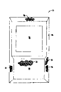
Figs. 2-3 illustrate another exemplary embodiment of flying insect station 10
of the present invention. Fig. 2 shows a front side elevation view and Fig. 3
shows a
backside elevation view of the flying insect station 10. The flying insect
station 10
includes a frame portion 24 having a generally inwardly tapered surface and
providing depth to the flying insect station 10. The surface geometry of the
frame
24 may be tapered, rounded, planar or another desired geometry. The backside
of
the frame includes an outer peripheral edge 34 (illustrated in Fig. 3) that is
generally
planar or resides in a single plane. The edge 34 allows the flying insect
station 10 to
be placed flush against a vertical surface such as a wall. The frame 24
provides
depth between the wall and other surfaces of the flying insect station 10. The
flying
insect station 10 includes a first surface 26 extending outward from the outer
peripheral edge 34 above the second surface 28. The frame 24 and first surface
26
are preferably a dark color, such as black. A cavity 36 is configured on the
backside
beneath the first surface 26 as best illustrated in Fig. 3. The cavity 36 may
include
means for supporting or holding an attractant, such as the attractant 16
illustrated in
Figs. 1A-1C. The attractant, as previously discussed, may be a serviceable,
replenishable, refreshable, or a consumable portion of the flying insect
station 10.
One or more surfaces of the flying insect station 10, such as surfaces
adjacent the
first surface 26, may include a vent 32 to allow a plume of attractant to
surround
surfaces adjacent and above the cavity 36. The second surface 28 is preferably
a
reflective surface similar to those discussed above. One or more of the outer
Date Recue/Date Received 2020-12-09
surfaces of the flying insect station 10 may include a suppression means 30,
such as
a pesticide for killing flying insects staging about the first surface 26 on
the second
surface 28 or frame 24. Like the attractant, the suppression means 30 may he a
rcplcnishable, refreshable, surfaceable or consumable portion of the flying
insect
station 10. The outer peripheral edge 34 of the flying insect station 10
orients the
first surface 26 and second surface 28 generally vertically relative to the
mounting
surface, such as a wall. In addition to being wall-mountable, the station 10
may he
configured as a free-standing device.
As discussed above, the flying insect station 10 may be used without an
attractant or the attractant may be a separate component of the flying insect
station
10, such as a free standing component placed or mounted near the flying insect
station 10. The flying insect station 10 may be constructed of economically
viable
material so as to allow the entirety of the flying insect station 10 to be a
consumable
and replaceable with a new one after the effectiveness of the suppression
means
and/or attractant have lost their residual effects. The flying insect station
illustrated
in Figs. 2-3 may include one or more of the features discussed above, alone or
in
combination with each other, integral to or separated from one another. For
example, the first surface 26 may be a separate component from the second
surface
which is a separate component from the suppression means and/or the
attractant.
The flying insect station 10 is preferably configured in a panel or frame
geometry
with one or more of the features of the station being replenishable,
refreshable,
serviceable or replaceable with a new component. The flying insect station 10
may
be configured for either indoor or outdoor use. For example, indoor
applications
often require compliance with industry specific regulations. Both attractants
and
suppression means approved for indoor use, such as in the food service
industry or
other applicable industries, may be used with the flying insect station 10 as
described above. These features allow the placement of the flying insect
station 10
at or near entrances, windows or where flies accumulate or congregate due to
one or
more of the behaviors identified above or the presence of food or breeding
materials.
The flying insect station 10 may also be configured for outdoor use by
including a
stronger attractant, increasing the size of the device and/or configuration of
the
geometry of the device so as to protect the attractant and/or suppression
means from
11
Date Recue/Date Received 2020-12-09
exposure to weather and other outdoor elements. The materials used to
configure
the flying insect station 10 may also be weather resistant, UV and heat
resistant. In
some outdoor environments, breeding or attracting grounds exist where the
flying
insect station 10 may be placed, such as for example without the use of an
attractant,
for attracting flies to one or more surfaces of the flying insect station 10
within a
shortened window of time for providing fly suppression.
Fig. 7 illustrates another exemplary aspect of the present invention. Fig. 7
illustrates a flying insect station 10 such as those previously illustrated.
The station
may be configured in the form of a panel which is preferably dark in color
(e.g.,
10 black). As noted above, the station may include a reflective portion
integrated into
the panel or as a separate component to the panel. The reflective portion
provides
specular reflection providing an appearance of an opening or a hole. The
arrangement of
the panel and reflective portion may be configured as described above. The
station
10 may also be configured as a panel alone without a reflective portion. The
panel
may take on various shapes and sizes and is preferably dark in color (e.g.,
black).
The station 10 may also include in addition to a reflective portion and
attractant, for
example placed within a housing, cavity or enclosure, for providing an
attractant
plume rising up around the staging areas (e.g., surfaces) of the station 10.
The
station 10 is placed, mounted near, attached to or otherwise placed in
proximity to a
means for insect suppression 38. According to an exemplary aspect of the
invention, the insect suppression means 38 is a fly suppression device such as
an
insect trap utilizing ultraviolet ("UV") light in combination with a long-
lasting, slow
release contact pesticide, such as a surface pesticide. The insect suppression
means
38 may also include an attractant (e.g., bait) together with or separate from
the
pesticide (e.g., glueboard). Further description of the insect trap suitable
for use
according to the invention is set forth in U.S. Patent Application Serial No.
12/471,087 (Ecolab USA Inc.).
Other insect traps, both light and non-light emitting traps, that may include
a bait and/or pesticide may also be used in combination with station 10 to
increase
the catch rates of the trap, and particularly within the first hour after an
insect is first
exposed to the system in Fig. 7. The combination of the fly attraction station
10
used in conjunction with insect suppression means 38 such as an insect light
trap
12
Date Recue/Date Received 2020-12-09
may be used on the interior or exterior of a structure. The use of a fly
attraction
station 10 in combination with insect suppression means 38 increases the catch
rate
of the insect suppression means 38. Observations were made of flying insect
behavior after they were released into a new environment that led to this
conclusion.
Specifically, the initial behavior of a flying insect during the first hour
after release
is categorically definable. These include, as discussed above at least in
part,
behaviors such as resting (e.g., sitting in one place without flying for 10
minutes or
more), low exploring (e.g., slow flight within one foot from the floor), mid-
exploring (e.g., flight between one and six feet from the floor), leaving
(rapid flight,
usually at a more rapid pace and usually more than six feet from the floor),
darting/chasing (predominantly male fly behavior attempting to mate with
female
flies as they fly by. Male fly stage on surfaces near fly-ways and dart after
passing
flies), breeding (predominantly female fly behavior in and on possible
breeding
material), and annoyance (fly behavior based near and/or on humans in the
area).
When a flying insect is first released into a new area, there is usually a
period of
acclimation where the fly stays close to the release point and begins to
explore
surrounding areas. Introduced flies may also establish a temporary "base" from
which they explore their surroundings. A base is a general area that a fly
will leave
from when exploring and return to at the end of the exploratory flight.
Annoyance
behavior is when the base is a human and the fly repeatedly lands on or near
the
human, even when the human moves to a new location. Exploratory flight is not
necessarily random. When flying, exploring flies appear to be attracted to
dark
objects and surfaces. Flies fly towards dark objects, repeatedly near dark
objects,
and around dark objects. Flies actively explore openings and dark, recessed
areas.
Flies actively fly to where movement, such as human activity, is found.
Resting
sites are also not necessarily random. Flies tend to prefer resting locations
with
broad views. They may land more often on dark surfaces, but this is not
necessarily
a significant trend or general rule.
Tests of the exemplary configuration of a station 10 and insect suppression
means 38 (e.g., insect light trap) shown in Fig. 7 were conducted. According
to one
aspect of the invention, elements, such as a panel, having a dark color (e.g.,
black)
are used in combination with insect suppression means 38 within a flight room.
Fig.
13
Date Recue/Date Received 2020-12-09
8 illustrates a bar chart evidencing the increased catch rate that was
observed with
the addition of a dark color in the vicinity of the insect suppression means
38. The
first two bars on the chart shown in Fig. 8 illustrate the increase in catch
rate, which
nearly doubles, when the insect suppression means 38 (e.g., the shroud of an
insect
trap) is a dark color such as black compared to one that is not. The mortality
percentages at one hour continue to increase when insect suppression means 38
that
is dark in color is used with a reflective surface such as a mirror or used in
combination with an attractant such as an odor or bait. The subsequent bars in
the
chart shown in Fig. 8 show a high mortality occurring within a one hour period
for
instances of use where a dark panel was used in combination with insect
suppression
means 38, such as an insect light trap. Thus, a dark element such as the dark
colored
station 10 (e.g., panel, surface or the like) illustrated in Fig. 7 in
combination with
insect suppression means 38, whether located near, attached to, or otherwise
placed
in proximity to the insect suppression means 38, exhibits an increased
mortality rate
within the one hour period as shown in Fig. 8.
The present invention contemplates that the panel as part of the station 10
illustrated in Fig. 7 may be configured in various sizes and shapes.
Preferably, the
panel is mountable on a vertical surface such as a wall, ceiling or floor.
Laboratory
tests were conducted to determine the optimal size of a dark panel placed in
proximity to insect suppression means 38 (e.g., insect light trap), and the
results are
shown in the plot illustrated in Fig. 9. "[he plot shows a significant
increase in the
catch rate as the surface area of the panel is increased, at least up to a
surface area of
roughly 400 square inches. Thus, catch rates did not show any significant
increase
for dark panel surface areas in excess of 400 square inches. Laboratory tests
were
also conducted to determine how close the station 10 should be positioned
relative to
the insect suppression means 38. Fig. 10 illustrates the results from a dark
panel
having a surface of roughly 432 square inches used at varying distances
relative to
the insect suppression means 38 (e.g., insect light trap). The percentage of
flies
caught by the insect suppression means 38 within one hour decreases by nearly
half
as the distance between the dark panel and the station increases up to 30
inches. The
highest effectiveness by percent mortality is realized by placement of the
insect
suppression means 38 next to or proximate the station 10 as shown in Fig. 7.
Thus,
14
Date Recue/Date Received 2020-12-09
the results show that a dark color panel such as the station 10 shown in Fig.
7 placed
in close proximity to insect suppression means 38 (e.g., an insect light trap)
can
significantly increase catch rates. Even a dark color panel having a si7e of
10 inches
by 10 inches, for example, can significantly increase catch rates when used in
combination with insect suppression means 38.
While the flying insect station 10 here and before described is effectively
adapted to fulfill the aforementioned objectives, it is to be understood that
the
invention is not intended to be limited to the specific preferred embodiments
of the
aspects disclosed and set forth above. Rather, it is to be taken as including
all
reasonable equivalents to the subject matter of the appended claims.
Date Recue/Date Received 2020-12-09