Note : Les descriptions sont présentées dans la langue officielle dans laquelle elles ont été soumises.
87506439
REMOVABLE STENT
TECHNICAL FIELD
The present disclosure relates generally to methods and apparatuses for
various
digestive ailments. More particularly, the disclosure relates to removable
stents for
extending through a valved region.
BACKGROUND
Implantable stents are devices that are placed in a tubular body structure,
such as a
blood vessel, esophagus, trachea, biliary tract, colon, intestine, stomach or
body cavity, to
provide support and to maintain the structure open. These devices are
manufactured by any
one of a variety of different manufacturing methods and may be used according
to any one
of a variety of methods. Of the known medical devices, delivery systems, and
methods,
each has certain advantages and disadvantages. There is an ongoing need to
provide
alternative medical devices and delivery/retrieval devices as well as
alternative methods
for manufacturing and using medical devices and delivery/retrieval devices.
SUMMARY
This disclosure is directed to several alternative designs, materials, methods
of
manufacturing medical device structures and associated uses thereof, such as
stents for
preventing leaks after an anastomosis surgery and/or treating various gastro-
intestinal,
digestive, or other ailments.
One illustrative embodiment is an implant including a first region, a second
region
and a third region. The first region has a proximal end region and a distal
end region. The
first region includes a flared proximal stent frame tapering radially inward
in a distal
direction. The second region has a proximal end region and a distal end
region. The second
region includes a flexible sleeve extending distally from the distal end
region of the first
region. The third region has a proximal end region and a distal end region.
The third region
includes a distal stent frame having an outer diameter less than an outer
diameter of the
1
Date Recue/Date Received 2022-05-18
CA 03102102 2020-11-30
WO 2019/236491
PCT/US2019/035239
flared proximal stent frame adjacent the proximal end region of the first
region and
extending distally from the distal end region of the second region. The
flexible sleeve is
configured to extend across a natural valve or sphincter and collapse upon
itself in response
to a radially applied force.
Additionally or alternatively, in another embodiment the implant includes a
first
retrieval suture configured to at least partially collapse the implant for
removal from a body
lumen.
Additionally or alternatively, in another embodiment the first retrieval
suture is
interwoven with the flared proximal stent frame and the distal stent frame.
Additionally or alternatively, in another embodiment the first retrieval
suture
includes a first suture loop interwoven with the flared proximal stent frame
adjacent the
proximal end region of the first region, a second suture loop interwoven with
the distal stent
adjacent the proximal end region of the third region, and a connecting suture
portion
extending between and coupled to the first and second suture loops.
Additionally or alternatively, in another embodiment a proximal force exerted
on
the first retrieval suture is configured to partially collapse the flared
proximal stent frame
adjacent the proximal end region of the first region.
Additionally or alternatively, in another embodiment once the outer diameter
of the
flared proximal stent frame adjacent the proximal end region of the first
region is partially
collapsed, the distal stent frame is configured to begin collapsing
simultaneously with
further collapsing of the proximal stent frame.
Additionally or alternatively, in another embodiment the connecting suture
portion
includes a slack portion which is configured to be drawn taut as the flared
proximal stent
frame is partially collapsed before the distal stent frame begins to collapse.
Additionally or alternatively, in another embodiment the first retrieval
suture
includes a first suture loop interwoven with the distal stent frame adjacent
the distal end
region of the third region, a second suture loop interwoven with the flared
proximal stent
frame adjacent the distal end region of the first region, and a connecting
suture portion
extending between and coupled to the first and second suture loops.
Additionally or alternatively, in another embodiment a distal force exerted on
the
first retrieval suture is configured to partially collapse the distal stent
frame adjacent the
distal end region of the third region.
2
CA 03102102 2020-11-30
WO 2019/236491
PCT/US2019/035239
Additionally or alternatively, in another embodiment the connecting suture
portion
includes a slack portion which is configured to be drawn taut as the distal
stent frame is
partially collapsed before the flared proximal stent frame begins to collapse.
Additionally or alternatively, in another embodiment the implant includes a
second
retrieval suture.
Additionally or alternatively, in another embodiment the second retrieval
suture is
interwoven with the flared proximal stent frame and the distal stent frame.
Additionally or alternatively, in another embodiment at least one of the first
or
second retrieval sutures is configured to at least partially collapse the
flared proximal stent
frame prior to collapsing the distal stent frame.
Additionally or alternatively, in another embodiment at least one of the first
or
second retrieval sutures is configured to at least partially collapse the
distal stent frame
prior to collapsing the flared proximal stent frame.
Additionally or alternatively, in another embodiment the flared proximal stent
frame has an outer profile configured to conform to an outlet of a stomach.
Additionally or alternatively, in another embodiment the outer diameter of the
flared proximal stent frame adjacent the proximal end region of the first
region is in the
range of about 25 millimeters (mm) to about 50 mm.
Additionally or alternatively, in another embodiment the outer diameter of the
distal
stent frame is in the range of about 15 millimeters (mm) to about 25 mm.
Another illustrative embodiment is an implant including an elongated tubular
member. The elongated tubular member includes a proximal stent, a flexible
sleeve, and a
distal stent. The proximal stent has a proximal end region and a distal end
region. The
proximal stent tapers from a first outer diameter adjacent the proximal end
region to a
second smaller outer diameter adjacent the distal end region. The flexible
sleeve has a
proximal end region and a distal end region. The flexible sleeve extends
distally from the
distal end region of the flared proximal stent. The distal stent has a
proximal end region
and a distal end region. The distal stent has an outer diameter less than the
first outer
diameter of the proximal stent and extends distally from the distal end region
of the flexible
sleeve. A first retrieval suture is interwoven with the proximal stent and the
distal stent.
The flexible sleeve is configured to extend across a natural valve or
sphincter and collapse
upon itself in response to an applied radial force.
3
87506439
Additionally or alternatively, in another embodiment the proximal stent is
configured to be positioned at a gastric outlet of a stomach and the flexible
sleeve is
configured to be positioned across a pyloric sphincter.
Additionally or alternatively, in another embodiment the applied radial force
is a
natural action of the pyloric sphincter.
Additionally or alternatively, in another embodiment the first retrieval
suture is
configured to at least partially collapse the proximal stent prior to begin
collapsing the distal
stent.
Additionally or alternatively, in another embodiment the first retrieval
suture is
configured to at least partially collapse the distal stent prior to begin
collapsing the proximal
stent.
Another illustrative embodiment is a method of removing or repositioning an
endoluminal implant. The method includes actuating an end of a retrieval
suture in a first
direction. The retrieval suture is interwoven within an end region of a first
stent of an
endoluminal implant and an end region of a second stent of the endoluminal
implant. The
first and second stents are separated and connected by a flexible polymeric
sleeve. The end
region of the first stent is configured to partially collapse before the end
of the second stent
begins to collapse.
Additionally or alternatively, in another embodiment the retrieval suture
includes a
first circumferential loop extending around the end region of the first stent,
a second
circumferential loop extending around the end of the second stent, and a
connecting suture
portion extending between the first circumferential loop and the second
circumferential
loop, wherein a slack portion of the connecting suture portion is drawn taut
as the end
region of the first stent is partially collapsed before the end of the second
stent begins to
collapse.
Additionally or alternatively, in another embodiment the first stent is
connected to
the second stent only by the flexible polymeric sleeve.
4
Date Recue/Date Received 2022-05-18
87506439
4a
According to one aspect of the present invention, there is provided an
implant,
the implant comprising: an elongated tubular member comprising: a first region
having a
proximal end region and a distal end region, the first region including a
flared proximal stent
frame tapering radially inward in a distal direction; a second region having a
proximal end
region and a distal end region, the second region including a flexible sleeve
extending distally
from the distal end region of the first region; a third region having a
proximal end region and
a distal end region, the third region including a distal stent frame having an
outer diameter
less than an outer diameter of the flared proximal stent frame adjacent the
proximal end
region of the first region and extending distally from the distal end region
of the second
region; and a first retrieval suture interwoven with the proximal stent frame
and the distal
stent frame, wherein the first retrieval suture is configured to partially
collapse the flared
proximal stent frame without collapsing the distal stent frame; wherein the
flexible sleeve is
configured to extend across a natural valve or sphincter and collapse upon
itself in response to
a radially applied force.
The above summary of exemplary embodiments is not intended to describe each
disclosed embodiment or every implementation of the present disclosure.
BRIEF DESCRIPTION OF THE DRAWINGS
Date Recue/Date Received 2022-05-18
CA 03102102 2020-11-30
WO 2019/236491
PCT/US2019/035239
The invention may be more completely understood in consideration of the
following
detailed description of various embodiments in connection with the
accompanying
drawings, in which:
FIG. 1 is a side view of an illustrative implant;
FIG. 2 is a side view of another illustrative implant;
FIG. 3 is a side view of another illustrative implant;
FIG. 4 is a side view of another illustrative implant;
FIG. 5 is a side view of another illustrative implant;
FIG. 6 is a side view of the illustrative implant of FIG. 1 with a retrieval
suture in a
first configuration;
FIG. 7 is a side view of the illustrative implant of FIG. 6 with the implant
in a
partially collapsed configuration;
FIG. 8 is a side view of the illustrative implant of FIG. 6 with the implant
in a fully
collapsed configuration;
FIG. 9 is a side view of the illustrative implant of FIG. 1 with a retrieval
suture in a
second configuration;
FIG. 10 is a side view of the illustrative implant of FIG. 9 with the implant
in a
partially collapsed configuration;
FIG. 11 is a side view of the illustrative implant of FIG. 9 with the implant
in a fully
collapsed configuration;
FIG. 12 is a side view of another illustrative implant a retrieval suture;
FIG. 13 is a side view of the illustrative implant of FIG. 12 with the implant
in a
partially collapsed configuration;
FIG. 14 is a side view of the illustrative implant of FIG. 12 with the implant
in a
fully collapsed configuration;
While the invention is amenable to various modifications and alternative
forms,
specifics thereof have been shown by way of example in the drawings and will
be described
in detail. It should be understood, however, that the intention is not to
limit aspects of the
invention to the particular embodiments described. On the contrary, the
intention is to
cover all modifications, equivalents, and alternatives falling within the
spirit and scope of
the invention.
DETAILED DESCRIPTION
5
CA 03102102 2020-11-30
WO 2019/236491
PCT/US2019/035239
For the following defined terms, these definitions shall be applied, unless a
different
definition is given in the claims or elsewhere in this specification.
All numeric values are herein assumed to be modified by the term "about,"
whether
or not explicitly indicated. The term "about" generally refers to a range of
numbers that
one of skill in the art would consider equivalent to the recited value (i.e.,
having the same
function or result). In many instances, the terms "about" may be indicative as
including
numbers that are rounded to the nearest significant figure.
The recitation of numerical ranges by endpoints includes all numbers within
that
range (e.g. 1 to 5 includes 1, 1.5, 2, 2.75, 3, 3.80, 4, and 5).
Although some suitable dimensions, ranges, and/or values pertaining to various
components, features and/or specifications are disclosed, one of the skill in
the art, incited
by the present disclosure, would understand desired dimensions, ranges and/or
values may
deviate from those expressly disclosed.
As used in this specification and the appended claims, the singular forms "a",
"an",
and "the- include plural referents unless the content clearly dictates
otherwise. As used in
this specification and the appended claims, the term "or" is generally
employed in its sense
including "and/or" unless the content clearly dictates otherwise.
For purposes of this disclosure, "proximal" refers to the end closer to the
device
operator during use, and "distal" refers to the end further from the device
operator during
use.
The following detailed description should be read with reference to the
drawings in
which similar elements in different drawings are numbered the same. The
detailed
description and the drawings, which are not necessarily to scale, depict
illustrative
embodiments and are not intended to limit the scope of the disclosure. The
illustrative
embodiments depicted are intended only as exemplary. Selected features of any
illustrative
embodiment may be incorporated into an additional embodiment unless clearly
stated to
the contrary.
It is noted that references in the specification to "an embodiment", "some
embodiments", "other embodiments", etc., indicate that the embodiment
described may
include a particular feature, structure, or characteristic, but every
embodiment may not
necessarily include the particular feature, structure, or characteristic.
Moreover, such
phrases are not necessarily referring to the same embodiment. Further, when a
particular
feature, structure, or characteristic is described in connection with one
embodiment, it
6
CA 03102102 2020-11-30
WO 2019/236491
PCT/US2019/035239
should be understood that such feature, structure, or characteristic may also
be used
connection with other embodiments whether or not explicitly described unless
cleared
stated to the contrary.
Gastric outlet obstruction (GOO) is the clinical and pathophysiological
consequence of any disease process that produces a mechanical impediment to
gastric
emptying. The presence of GOO can be classified into disease conditions that
affect the
antrum and pylorus that lead to pyloric dysfunction or disease conditions of
the proximal
duodenum that restrict efferent flow. Clinical conditions such as peptic ulcer
disease
(PUD), pyloric stenosis, and gastric polyps represent etiologies for the
former with
pancreatic carcinoma, ampullary cancer, duodenal cancer, cholangiocarcinomas
representing etiologies for the latter. In some instances, GOO may be directly
treated
through stenting the location using gastrointestinal (GI) self-expanding
stents. However,
placing a stent across the pyloric valve may leave the pylorus in a
continually open position.
However, this may result in gastric leakage into the duodenum. Alternative
stent designs
are desired to allow the immediate blockage to be opened while allowing for
natural pyloric
function to be retained.
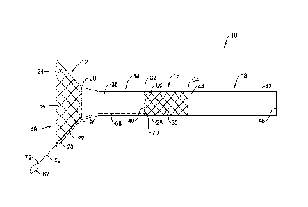
FIG. 1 illustrates a side view of an illustrative endoluminal implant 10
including a
plurality of regions, including, a first or proximal region 12, a second or
intermediate region
14, a third or intermediate region 16, and a fourth or distal region 18. While
the illustrative
implant 10 is shown and described as having four regions 12, 14, 16, 18, it is
contemplated
the implant 10 may include any number of regions desired, such as, but not
limited to, one,
two, three, four, or more. Further, the regions 12, 14, 16. 18 may be any
combination of
structures and materials desired. In some cases, the implant 10 may include
features (e.g.,
anti-migration flares, fixation spikes, sutures, etc.) to prevent
distal/proximal displacement
and/or migration of the implant 10, once the implant 10 is positioned and
expanded in the
body lumen. The implant 10 may include a lumen 48 extending entirely through
the length
of the implant 10, such as from a proximal end 24 of the first region 12 to a
distal end 46
of the fourth region 18.
In some cases, the first region 12 may take the form of a stent 20 including
an
elongated tubular stent frame 22 defining a lumen. The stent 20 may be may be
entirely,
substantially, or partially covered with a polymeric covering, such as a
coating (not
explicitly shown). The covering may be disposed on an inner surface and/or
outer surface
of the stent 20, as desired. When so provided a polymeric covering may reduce
or eliminate
7
CA 03102102 2020-11-30
WO 2019/236491
PCT/US2019/035239
tissue ingrowth and/or reduce food impaction through interstices of the stent
20 into the
lumen. It is contemplated that leaving an outer rim or a portion of the
surface uncovered,
an area of hyperplasia can be generated which would create a seal. The stent
20 may include
regions of differing diameters. For example, the stent 20 may include a flared
(e.g.,
enlarged relative to other portions of the stent 20) proximal end region 24
tapering radially
inward to a distal end region. While not explicitly shown, the stent 20 may
include regions
of constant diameter or increasing diameters (e.g., in the distal direction),
if so desired. The
stent frame 22 may be expandable between a radially collapsed delivery
configuration and
a radially expanded deployed configuration. The expanded configuration may
secure the
implant 10 at the desired location in a body lumen.
In some cases, the third region 16 may take the form of a stent 28 including
an
elongated tubular stent frame 30 defining a lumen. The stent 28 may be may be
entirely,
substantially or partially, covered with a polymeric covering, such as a
coating (not
explicitly shown). The covering may be disposed on an inner surface and/or
outer surface
of the stent 28, as desired. When so provided a polymeric covering may reduce
or eliminate
tissue ingrowth and/or reduce food impaction through interstices of the stent
28 into the
lumen. The stent 28 may have a uniform outer diameter from its proximal end
region 32
to its distal end region 34. However, the stent 28 may include regions of
differing diameters
if so desired. The stent frame 30 may be expandable between a radially
collapsed delivery
configuration and a radially expanded deployed configuration. The expanded
configuration
may secure the implant 10 at the desired location in a body lumen. While not
explicitly
shown, in some embodiments, the distal stent 28 may extend distally to a
distal end of the
implant 10. Some additional but non-limiting alternative configurations are
shown and
described with respect to FIGS. 2-5.
The stent frames 22, 30 may have a woven structure, fabricated from a number
of
filaments. In some embodiments, the stent frames 22, 30 may be knitted with
one filament,
as is found, for example, in the ULTRAFLEXTm stents, made and distributed by
Boston
Scientific Corp. In other embodiments, the stent frames 22, 30 may be braided
with several
filaments, as is found, for example, in the WALLFLEX , WALLSTENTC , and
POLYFLEX stents, made and distributed by Boston Scientific Corp. In yet
another
embodiment, the stent frames 22, 30 may be of a knotted type, such the
PRECISION
COLONICTM stents made by Boston Scientific Corp. In still another embodiment,
the stent
frames 22, 30 may be laser cut, such as the EPICTM stents made by Boston
Scientific Corp.
8
CA 03102102 2020-11-30
WO 2019/236491
PCT/US2019/035239
It is contemplated that the stent frames 22, 30 may be formed having the same
structure as
one another or having a different structure from one another.
It is contemplated that the stent frames 22, 30 can be made from a number of
different materials such as, but not limited to, metals, metal alloys, shape
memory alloys
and/or polymers, as desired, enabling the stents 20, 28 to be expanded into
shape when
accurately positioned within the body. The material of the stent frames 22, 30
may be the
same or different, as desired. In some instances, the material may be selected
to enable the
stents 20, 28 to be removed with relative ease as well. For example, the stent
frames 22,
30 can be formed from alloys such as, but not limited to, nitinol and
ELGILOYO.
to Depending the on material selected for construction, the stents 20, 28
may be self-
expanding (i.e., configured to automatically radially expand when
unconstrained). In some
embodiments, fibers may be used to make the stent frames 22, 30, which may be
composite
fibers, for example, having an outer shell made of nitinol having a platinum
core. It is
further contemplated the stent frames 22, 30 may be formed from polymers
including, but
not limited to, polyethylene terephthalate (PET). In some embodiments, the
stents 20, 28
may be self-expanding while in other embodiments, the stents 20, 28 may be
expanded by
an expansion device (such as, but not limited to a balloon inserted within a
lumen 48 of the
implant 10). As used herein the term "self-expanding" refers to the tendency
of the stent
to return to a preprogrammed diameter when unrestrained from an external
biasing force
(for example, but not limited to a delivery catheter or sheath).
One or both of the stents 20, 28 may include a one-way valve, such as an
elastomeric
slit valve or duck bill valve, positioned within the lumen 48 thereof to
prevent retrograde
flow of fluid or other material, such as gastrointestinal fluids.
In some cases, the second portion 14 may take the form of a proximal flexible
sleeve
36 and the fourth portion 18 may take the form of a distal flexible sleeve 42.
The proximal
sleeve 36 may extend between the distal end of the proximal stent 20 and the
proximal end
of the distal stent 28. For example, the proximal sleeve 36 may be connected,
affixed, or
secured to the distal end region 26 of the first or proximal stent 20 adjacent
to a proximal
end region 38 of the sleeve 36. The proximal sleeve 36 may also be connected,
affixed, or
secured to the proximal end region 32 of the second or distal stent 28
adjacent to a distal
end region 40 of the proximal sleeve 36. In some cases, the proximal sleeve 36
may overlap
a portion or all of the proximal stent 20 and/or a portion or all of the
distal stent 28. In some
instances, the proximal sleeve 36 may be devoid of any structural components
tending to
9
87506439
hold the lumen 48 through the sleeve 36 open, thus allowing the sleeve 36 to
collapse
inward upon itself when subjected to the force of the pyloric valve closing
off the lumen
48. The distal sleeve 42 may be connected, affixed, or secured to the distal
end region 44
of the second or distal stent 28 adjacent to a proximal end region 44 of the
sleeve 42 and
extend distally to a distal end region 46. In some cases, the distal sleeve 42
may overlap a
portion or all of the distal stent 28. It is contemplated that the sleeve 36,
42 may be formed
as individual flexible membranes or as a single unitary structure, as desired.
In some
embodiments, the sleeves 36, 42 may extend partially, substantially, or all of
the length of
the implant 10 and cover all other portions (exterior surface and/or interior
surface) of the
implant 10, including the stents 20, 28. Said differently, while the regions
12, 14, 16, 18
have been described as a stent 20, 28 or a sleeve 36, 42, each region may
include one or
both of a frame structure and flexible sleeve structure. The sleeves 36, 42
may be secured
to one or both of the stents 20, 28 by an adhesive or other methods known in
the art,
including by not limited to thermal methods, mechanical methods, etc.
The sleeves 36, 42 may each have an elongated, tubular shape defining a lumen.
The lumen of the stents 20, 28 and the flexible sleeves 36, 42 may be fluidly
connected to
form the lumen 48 of the implant 10. It is contemplated that one or more of
the regions 12,
14, 16, 18 of the implant 10 may include more than one lumen, as desired. The
sleeves 36,
42 may be a thin flexible membrane that readily collapses on itself For
example one or
both of the sleeves may be configured to collapse upon itself under the
applied radial force
exerted by a natural valve or sphincter when the implant 10 is deployed in a
body lumen
having a natural valve or sphinctor. However, one or both of the sleeves 36,
42 may be
provided with a radial support to hold it in the expanded configuration. Some
examples
and discussion of illustrative supports may be found in co-pending Patent
Application
Number 62/419,707, filed on November 9, 2016, titled DEPLOYABLE SLEEVES AND
RELATED METHODS.
The sleeves 36, 42 may include one or more of the following polymer materials:
polyethylene, polypropylene, polystyrene, polyester, biosorbable plastics
(e.g., polylactic
acid), polycarbonate, polyvinyl chloride, polyacrylate, acrylate, polysulfone,
poly etheretherketone, thermoplastic elastomers, thermoset elastomers (e.g.,
silicone), poly-
p-xylylene (parylene), flouropolymers (e.g., polytetrafluoroethylene (PTFE),
polyvinylidene fluoride (PVDF), poly(vinylidene fluoride-co-
hexafluoropropylene)
(PVDFHFP)), bioplastics (e.g., cellulose acetate). The sleeves 36, 42 may
additionally or
Date Recue/Date Received 2022-05-18
CA 03102102 2020-11-30
WO 2019/236491
PCT/US2019/035239
alternatively include one or more of: polyurethane and its copolymers,
ethylene vinyl-
acetate, polyethylene terephthalate (PET), poly olefins, cellulosics,
polyamides,
acrylonitrile butadiene styrene copolymers, styrene isoprene butadiene (SIBS)
block
copolymers, acrylics, poly(glycolide-lactide) copolymer, Tecothane, PEBAX,
poly(y-
caprolactone), poly(y-hydroxybutyrate), polydioxanone, poly(y-ethyl
glutamate),
polyiminocarbonates, poly(ortho ester), and/or polyanhydrides. Blends of the
above
polymers may also be employed, such as, but not limited to ChronoFlex ,
manufactured
by AdvanSource Biomaterials, based in Wilmington, MA, a family of biodurable
aromatic
polycarbonate based thermoplastic urethanes.
In further detail, the implant 10 may be generally cylindrical in shape,
although this
is not required, substantially flexible, and sized appropriately for a
convenient
accommodation within the digestive tract. It is contemplated that various
shapes, sizes and
designs of the implant may be constructed depending on the size and geometry
of the
cavities where the implant 10 has to be placed. In various examples, the
implant 10 may
have a length between 3-12 inches, 3-6 inches, 0.5-20 feet (0.15-6.1 meters),
between 3-5
feet (0.9-1.5 meters), or about 2-4 feet (0.6-1.2 meters). However, the
implant 10 may have
a length of less than 0.5 feet (0.15 meters) or greater than 20 feet (6.1
meters) in some
instances.
In one illustrative example, the implant 10 may be sized to be positioned
within the
outlet of the stomach, extend across the pylorus and into the duodenum to
treat, for
example, gastric outlet obstruction. In such an example, the proximal stent 20
may be sized
to prevent the implant 10 from migrating distally through the stomach outlet.
For example,
the proximal end region 24 of the proximal stent 20 may have an outer diameter
50 in the
range of about 25 millimeters (mm) to about 50 mm. It is contemplated that the
shape of
the proximal stent 20 may be formed to match or generally conform to the shape
of the
stomach exit. The proximal sleeve 36 may be configured to extend across the
pylorus and
may have a length 54 in the range of about 6 mm to about 15 mm. The distal
stent 28 and
the distal sleeve 42 may be sized to be positioned within the duodenal bulb
and duodenum,
respectively, and may have an outer diameter 52 in the range of about 15 mm to
about 25
mm. The distal stent 28 and the distal sleeve 42 may together have a length 56
in the range
of about 60 mm to about 150 mm. When the distal stent 28 extends distally to a
distal end
of the implant 10, the distal stent 28 may have a length 56 in the range of
about 60 mm to
about 150 mm. This is just an example. It is contemplated that the proximal
sleeve 36
11
CA 03102102 2020-11-30
WO 2019/236491
PCT/US2019/035239
and/or the distal sleeve 42 may be positioned across other valved or sphincter
regions with
the proximal and/or distal stents 20, 28 sized and shaped for the adjacent
anatomy.
Once implanted in a patient, the stents 20, 28 may exert a radially outward
force to
help secure the implant 10 to the body lumen. The implant 10 may be positioned
in the
antrum-pyloric-duodenum, esophagus, the gastro-esophageal junction (GEJ)
region (e.g.,
at or near the cardia with the sleeve 24 extending into the esophagus), or at
or near the
pylorus with the sleeve 24 extending through the stomach or other portions of
the gastro-
intestinal system. In one example, the implant 10 may be positioned such that
the proximal
stent 20 is positioned at the stomach outlet with the proximal sleeve 36
bridging the pylorus.
The flared structure of the proximal stent 20 may use the stomach to anchor
the implant 10
and act as an anti-migration mechanism for the implant 10. For example, the
large outer
diameter 50 of the proximal end 24 of the proximal stent 20 may engage the
stomach outlet
to prevent or limit movement of the implant 10. The distal stent 28 may be
placed within
the duodenal bulb and the distal sleeve 42 may extend into the duodenum. The
proximal
sleeve 36 may be coupled to both the proximal stent 20 and the distal stent 28
such that a
relative position of each section is fixed.
In some instances, the function of the pyloric valve may not have been
impacted or
degraded by the disease state which has caused the gastric outlet obstruction.
In such an
instance, it may be desirable to open the obstruction while still allowing for
normal function
of the pyloric valve. As described above, the proximal sleeve 36 may be formed
from a
flexible material. In other words, the proximal sleeve 36 may be free from any
structure
configured to exert a radially outward force on the surrounding tissue and may
collapse
upon itself under the applied radial force exerted by the natural valve or
sphincter. This
may allow the pyloric valve to function in a natural manner (e.g., to open and
close). The
distal stent 28 may be positioned adjacent to the gastric outlet obstruction.
The stent frame
of the distal stent 28 may be constructed with sufficient radial force (e.g.,
to exert a
sufficient radially outward force) to open the obstruction caused by the
disease state.
FIG. 2 illustrates a side view of another illustrative implant 100 including a
plurality
of regions, including, a first or proximal region 102, a second or
intermediate region 104,
30 and a third or
distal region 106. The illustrative implant 100 may be similar in form and
function to the implant 10 described above. While the illustrative implant 100
is shown and
described as having three regions 102, 104, 106, it is contemplated the
implant 100 may
include any number of regions desired, such as, but not limited to, one, two,
three, four, or
12
CA 03102102 2020-11-30
WO 2019/236491
PCT/US2019/035239
more. Further, the regions 102, 104, 106 may be any combination of structures
and
materials desired. In some cases, the implant 100 may include features (e.g.,
anti-migration
flares, fixation spikes, sutures, etc.) to prevent distal/proximal
displacement and/or
migration of the implant 100, once the implant 100 is positioned and expanded
in the body
lumen. The implant 100 may include a lumen 108 extending from a proximal end
114 of
the first region 102 to a distal end 124 of the third region 106.
In some cases, the first region 102 may take the form of a stent 110 including
an
elongated tubular stent frame 112 defining a lumen which may be similar in
form and
function to the proximal stent 20 described above. The stent 110 may be
entirely.
substantially or partially, covered with a polymeric covering, such as a
coating (not
explicitly shown). The covering may be disposed on an inner surface and/or
outer surface
of the stent frame 112, as desired. When so provided a polymeric covering may
reduce or
eliminate tissue ingrowth and/or reduce food impaction. The stent 110 may
include regions
of differing diameters. For example, the stent 110 may include a flared (e.g.,
enlarged
relative to other portions of the stent 110) proximal end region 114 tapering
radially inward
in a distal direction to a distal end region 116. While not explicitly shown,
the stent 110
may include regions of constant diameter or increasing diameters (e.g.,
increasing in the
distal direction), if so desired. The stent frame 112 may be expandable
between a radially
collapsed delivery configuration and a radially expanded deployed
configuration. The
expanded configuration may secure the implant 100 at the desired location in a
body lumen.
In some cases, the third region 106 may take the form of a stent 118 including
an
elongated tubular stent frame 120 defining a lumen which may be similar in
form and
function to the distal stent 28 described above. The stent 118 may be
entirely, substantially
or partially, covered with a polymeric covering, such as a coating (not
explicitly shown).
The covering may be disposed on an inner surface and/or outer surface of the
stent frame
120, as desired. When so provided a polymeric covering may reduce or eliminate
tissue
ingrowth and/or reduce food impaction. The stent 118 may have a uniform outer
diameter
from its proximal end region 122 to its distal end region 124. However, the
stent 118 may
include regions of differing diameters if so desired. The stent frame 120 may
be expandable
between a radially collapsed delivery configuration and a radially expanded
deployed
configuration. The expanded configuration may secure the implant 100 at the
desired
location in a body lumen. While not explicitly shown, in some embodiments, the
distal
stent 118 may extend distally to a distal end of the implant 100.
13
CA 03102102 2020-11-30
WO 2019/236491
PCT/US2019/035239
In some cases, the second portion 104 may take the form of a flexible sleeve
126.
The sleeve 126 may extend between the distal end of the proximal stent 110 and
the
proximal end of the distal stent 118. For example, the sleeve 126 may be
connected,
affixed, or secured to the distal end region 116 of the first or proximal
stent 110 adjacent
to a proximal end region 128 of the sleeve 126. The sleeve 126 may also be
connected,
affixed, or secured to the proximal end region 122 of the second or distal
stent 118 adjacent
to a distal end region 130 of the sleeve 126. In some cases, the sleeve 126
may overlap a
portion or all of the proximal stent 110 and/or a portion or all of the distal
stent 118. Said
differently, the sleeve 126 may extend from the proximal end region 114 of the
proximal
stent 110 to the distal end region 124 of the distal stent 118 such that the
implant 100 is
fully covered. Alternatively, and/or additionally, one or both of the proximal
stent 110 and
the distal stent 118 may be covered with a material or structure different
from the sleeve
126 to provide a fully covered implant 100. The sleeve 126 may be secured to
one or both
of the stents 110, 118 by an adhesive or other methods known in the art,
including by not
limited to thermal methods, mechanical methods, etc.
The sleeve 126 may have an elongated, tubular shape defining a lumen which may
be similar in form or function to the sleeves 36, 42 described above. The
lumen of the stents
110, 118 and the flexible sleeve 126 may be fluidly connected to form the
lumen 108 of the
implant 100. It is contemplated that one or more of the regions 102, 104, 106
of the implant
100 may include more than one lumen, as desired. The sleeve 126 may be a thin
flexible
membrane that readily collapses on itself. However, in some instances, the
sleeve 126 may
be provided with a radial support.
The sleeve 126 may include one or more longitudinally extending slots 132
extending through a thickness of the sleeve 126. The removal of material to
form the slots
132 may allow for a connecting element to remain between the proximal stent
110 and the
distal stent 118 while increasing the deformability and/or moveability of the
sleeve 126.
Thus, when the sleeve 126 is positioned across a valve or sphincter, such as,
but not limited
to the pyloric valve, the reduced amount of material placed across the valve
region may
further allow for normal valve function. The sleeve 126 may include any number
of
longitudinally extending slots 132 desired, such as, but not limited to one,
two, three, four,
or more. The slots 132 may be positioned uniformly about a circumference of
the sleeve
126 (e.g., having a uniform distance between adjacent slots 132) or
eccentrically about a
circumference of the sleeve 126 (e.g., having an unequal distant between
adjacent slots
14
CA 03102102 2020-11-30
WO 2019/236491
PCT/US2019/035239
132). While the slots 132 have been described as extending longitudinally
(e.g., along a
longitudinal axis of the implant 100), it is contemplated that the slots 132
may extend along
non-parallel angles relative to the longitudinal axis of the implant 100. For
example, the
slots 132 may extend in a helical manner about a circumference of the sleeve
126.
In one illustrative example, the implant 100 may be sized to be positioned
within
the outlet of the stomach, extend across the pylorus and into the duodenum to
treat, for
example, gastric outlet obstruction. In such an example, the proximal stent
110 may be
sized to prevent implant 100 from migrating distally through the stomach
outlet. For
example, the proximal end region 114 of the proximal stent 110 may have an
outer diameter
134 in the range of about 25 millimeters (mm) to about 50 mm. It is
contemplated that the
shape of the proximal stent 110 may be formed to match or generally conform to
the shape
of the stomach exit. The sleeve 126 may be configured to extend across the
pylorus and
may have a length 136 in the range of about 6 mm to about 15 mm. The distal
stent 118
may be sized to be positioned within the duodenal bulb and duodenum,
respectively, and
may have an outer diameter 138 in the range of about 15 mm to about 25 mm. The
distal
stent 118 may have a length 140 in the range of about 60 mm to about 150 mm.
This is
just an example. It is contemplated that the sleeve 126 may be positioned
across other
valved or sphincter regions with the proximal and/or distal stents 110, 118
sized and shaped
for the adjacent anatomy.
Once implanted in a patient, the stents 110, 118 may exert a radially outward
force
to help secure the implant 100 to the body lumen. The implant 100 may be
positioned in
the esophagus, the gastro-esophageal junction (GEJ) region, or at or near the
pylorus with
the sleeve 114 extending through the stomach or other portions of the gastro-
intestinal
system. In one example, the implant 100 may be positioned such that the
proximal stent
110 is positioned at the stomach outlet with the sleeve 126 bridging the
pylorus. The flared
structure of the proximal stent 110 may use the stomach to anchor the implant
100 and act
as an anti-migration mechanism for the implant 100. For example, the large
outer diameter
134 of the proximal end 114 of the proximal stent 110 may engage the stomach
outlet to
prevent or limit movement of the implant 100. The distal stent 118 may be
placed within
the duodenal bulb and may extend into the duodenum. The sleeve 126 may be
coupled to
both the proximal stent 110 and the distal stent 118 such that a relative
position of each
section is fixed.
CA 03102102 2020-11-30
WO 2019/236491
PCT/US2019/035239
In some instances, the function of the pyloric valve may not have been
impacted or
degraded by the disease state which has caused the gastric outlet obstruction.
In such an
instance, it may be desirable to open the obstruction while still allowing for
normal function
of the pyloric valve. As described above, the sleeve 126 may be formed from a
flexible
material which may be made more flexible or pliable through the addition of
slots 132. In
other words, the sleeve 126, and thus the length of the intermediate region
104 between the
proximal stent 110 and the distal stent 118, may be free from any structure
configured to
exert a radially outward force on the surrounding tissue. This may allow the
pyloric valve
to function in a natural manner (e.g.. to open and close). The distal stent
118 may be
positioned adjacent to the gastric outlet obstruction. The stent frame 120 of
the distal stent
118 may be constructed with sufficient radial force (e.g., to exert a
sufficient radially
outward force) to open the obstruction caused by the disease state.
FIG. 3 illustrates a side view of another illustrative implant 150 including a
plurality
of regions, including, a first region 152, a second region 154, and a third
region 156. The
illustrative implant 150 may be similar in form and function to the implant 10
described
above. While the illustrative implant 150 is shown and described as having
three regions
152, 154, 156, it is contemplated the implant 150 may include any number of
regions
desired, such as, but not limited to, one, two, three, four, or more. Further,
the regions 152,
154, 156 may be any combination of structures and materials desired. In some
cases, the
implant 150 may include features (e.g., anti-migration flares, fixation
spikes, sutures, etc.)
to prevent distal/proximal displacement and/or migration of the implant 150,
once the
implant 150 is positioned and expanded in the body lumen. The implant 150 may
include
a lumen 158 extending from a proximal end 164 of the first region 152 to a
distal end 174
of the third region 156.
In some cases, the first region 152 may take the form of a stent 160 including
an
elongated tubular stent frame 162 defining a lumen which may be similar in
form and
function to the proximal stent 20 described above. The stent 160 may be
entirely,
substantially or partially, covered with a polymeric covering, such as a
coating (not
explicitly shown). The covering may be disposed on an inner surface and/or
outer surface
of the stent frame 162, as desired. When so provided a polymeric covering may
reduce or
eliminate tissue ingrowth and/or reduce food impaction. The stent 160 may
include regions
of differing diameters. For example, the stent 160 may include a flared (e.g.,
enlarged
relative to other portions of the stent 160) proximal end region 164 tapering
radially inward
16
CA 03102102 2020-11-30
WO 2019/236491
PCT/US2019/035239
in a distal direction to a distal end region 166. While not explicitly shown,
the stent 160
may include regions of constant diameter or increasing diameters (e.g.,
increasing in the
distal direction), if so desired. The stent frame 162 may be expandable
between a radially
collapsed delivery configuration and a radially expanded deployed
configuration. The
expanded configuration may secure the implant 150 at the desired location in a
body lumen.
In some cases, the third region 156 may take the form of a stent 168 including
an
elongated tubular stent frame 170 defining a lumen which may be similar in
form and
function to the distal stent 28 described above. The stent 168 may be
entirely, substantially
or partially, covered with a polymeric covering, such as a coating (not
explicitly shown).
For example, a partial covering could be used to cause hyperplasia for
fixation or, for
example, for biliary, or other, access. The covering may be disposed on an
inner surface
and/or outer surface of the stent frame 170, as desired. When so provided a
polymeric
covering may reduce or eliminate tissue ingrowth and/or reduce food impaction.
The stent
168 may have a uniform outer diameter from its proximal end region 172 to its
distal end
region 174. However, the stent 168 may include regions of differing diameters
if so desired.
The stent frame 170 may be expandable between a radially collapsed delivery
configuration
and a radially expanded deployed configuration. The expanded configuration may
secure
the implant 150 at the desired location in a body lumen. While not explicitly
shown, in
some embodiments, the distal stent 168 may extend distally to a distal end of
the implant
150.
In some cases, the second portion 154 may take the form of a flexible sleeve
176.
The sleeve 176 may extend between the distal end of the proximal stent 160 and
the
proximal end of the distal stent 168. For example, the sleeve 176 may be
connected,
affixed, or secured to the distal end region 166 of the first or proximal
stent 160 adjacent
to a proximal end region 178 of the sleeve 176. The sleeve 176 may also be
connected,
affixed, or secured adjacent or distal to the proximal end region 172 of the
second or distal
stent 168 adjacent to a distal end region 180 of the sleeve 176. In some
cases, the sleeve
176 may overlap a portion or all of the proximal stent 160 and/or a portion of
the distal
stent 168. Said differently, the sleeve 176 may extend from the proximal end
region 164 of
the proximal stent 160 to a location proximal to the distal end region 174 of
the distal stent
168 such that the implant 150 is not fully covered. For example, at least a
portion of the
distal stent 168 may be a bare stent. This may allow for tissue ingrowth to
further secure
the implant 150. In some instances, all or a portion of the proximal stent 160
may be bare.
17
CA 03102102 2020-11-30
WO 2019/236491
PCT/US2019/035239
Alternatively, and/or additionally, one or both of the proximal stent 160 and
the distal stent
168 may be covered with a material or structure different from the sleeve 176
to provide a
partially covered implant 150. The sleeve 176 may be secured to one or both of
the stents
160, 168 by an adhesive or other methods known in the art, including by not
limited to
thermal methods, mechanical methods, etc.
The sleeve 176 may have an elongated, tubular shape defining a lumen which may
be similar in form or function to the sleeves 36, 42 described above. The
lumen of the stents
160, 168 and the flexible sleeve 176 may be fluidly connected to form the
lumen 158 of the
implant 150. It is contemplated that one or more of the regions 152, 154, 156
of the implant
150 may include more than one lumen, as desired. The sleeve 176 may be a thin
flexible
membrane that readily collapses on itself. However, in some instances, the
sleeve 176 may
be provided with a radial support.
The sleeve 176 may include one or more apertures 182 extending through a
thickness of the sleeve 176. For example, the sleeve 176 may have a mesh-like
structure.
The removal of material to form the apertures 182 may allow for a connecting
element to
remain between the proximal stent 160 and the distal stent 168 while
increasing the
deformability and/or moveability of the sleeve 176. Thus, when the sleeve 176
is positioned
across a valve or sphincter, such as, but not limited to the pyloric valve,
the reduced amount
of material placed across the valve region may further allow for normal valve
function. The
sleeve 176 may include any number of apertures 182 desired, such as, but not
limited to
one, two, three, ten, twenty, fifty, or more. The apertures 182 may be
positioned uniformly
about a circumference and/or length of the sleeve 176 (e.g., having a uniform
distance
between adjacent apertures 182) or eccentrically about a circumference and/or
length of the
sleeve 176 (e.g., having an unequal distant between adjacent apertures 182).
In one illustrative example, the implant 150 may be sized to be positioned
within
the outlet of the stomach, extend across the pylorus and into the duodenum to
treat, for
example, gastric outlet obstruction. In such an example, the proximal stent
160 may be
sized to prevent implant 150 from migrating distally through the stomach
outlet. For
example, the proximal end region 164 of the proximal stent 160 may have an
outer diameter
184 in the range of about 25 millimeters (mm) to about 50 mm. It is
contemplated that the
shape of the proximal stent 160 may be formed to match or generally conform to
the shape
of the stomach exit. The sleeve 176 may be configured to extend across the
pylorus and
may have a length 186 in the range of about 6 mm to about 15 mm. The distal
stent 168
18
CA 03102102 2020-11-30
WO 2019/236491
PCT/US2019/035239
may be sized to be positioned within the duodenal bulb and duodenum,
respectively, and
may have an outer diameter 188 in the range of about 15 mm to about 25 mm. The
distal
stent 168 may have a length 190 in the range of about 60 mm to about 150 mm.
This is
just an example. It is contemplated that the sleeve 176 may be positioned
across other
valved or sphincter regions with the proximal and/or distal stents 160, 168
sized and shaped
for the adjacent anatomy.
Once implanted in a patient, the stents 160, 168 may exert a radially outward
force
to help secure the implant 150 to the body lumen. The implant 150 may be
positioned in
the esophagus, the gastro-esophageal junction (GEJ) region, or at or near the
pylorus with
I() the sleeve 164
extending through the stomach or other portions of the gastro-intestinal
system. In one example, the implant 150 may be positioned such that the
proximal stent
160 is positioned at the stomach outlet with the sleeve 176 bridging the
pylorus. The flared
structure of the proximal stent 160 may use the stomach to anchor the implant
150 and act
as an anti-migration mechanism for the implant 150. For example, the large
outer diameter
184 of the proximal end 164 of the proximal stent 160 may engage the stomach
outlet to
prevent or limit movement of the implant 150. The distal stent 168 may be
placed within
the duodenal bulb and may extend into the duodenum. The sleeve 176 may be
coupled to
both the proximal stent 160 and the distal stent 168 such that a relative
position of each
section is fixed.
In some instances, the function of the pyloric valve may not have been
impacted or
degraded by the disease state which has caused the gastric outlet obstruction.
In such an
instance, it may be desirable to open the obstruction while still allowing for
normal function
of the pyloric valve. As described above, the sleeve 176 may be formed from a
flexible
material which may be made more flexible or pliable through the addition of
apertures 182.
In other words, the sleeve 176, and thus the length of the intermediate region
154 between
the proximal stent 160 and the distal stent 168, may be free from any
structure configured
to exert a radially outward force on the surrounding tissue. This may allow
the pyloric valve
to function in a natural manner (e.g., to open and close). The distal stent
168 may be
positioned adjacent to the gastric outlet obstruction. The stent frame 170 of
the distal stent
168 may be constructed with sufficient radial force (e.g., to exert a
sufficient radially
outward force) to open the obstruction caused by the disease state.
FIG. 4 illustrates a side view of another illustrative implant 200 including a
plurality
of regions, including, a first region 202, a second region 204, and a third
region 206. The
19
CA 03102102 2020-11-30
WO 2019/236491
PCT/US2019/035239
illustrative implant 200 may be similar in form and function to the implant 10
described
above. While the illustrative implant 200 is shown and described as having
three regions
202, 204, 206, it is contemplated the implant 200 may include any number of
regions
desired, such as, but not limited to, one, two, three, four, or more. Further,
the regions 202,
204, 206 may be any combination of structures and materials desired. In some
cases, the
implant 200 may include features (e.g., anti-migration flares, fixation
spikes, sutures, etc.)
to prevent distal/proximal displacement and/or migration of the implant 200,
once the
implant 200 is positioned and expanded in the body lumen. The implant 200 may
include
a lumen 208 extending from a proximal end 214 of the first region 202 to a
distal end 224
1() of the third region 206.
In some cases, the first region 202 may take the form of a stent 210 including
an
elongated tubular stent frame 212 defining a lumen which may be similar in
form and
function to the proximal stent 20 described above. The stent 210 may be
entirely,
substantially or partially, covered with a polymeric covering, such as a
coating (not
explicitly shown). The covering may be disposed on an inner surface and/or
outer surface
of the stent frame 212, as desired. When so provided a polymeric covering may
reduce or
eliminate tissue ingrowth and/or reduce food impaction. The stent 210 may
include regions
of differing diameters. For example, the stent 210 may include a flared (e.g.,
enlarged
relative to other portions of the stent 210) proximal end region 214 tapering
radially inward
in a distal direction to a distal end region 216. While not explicitly shown,
the stent 210
may include regions of constant diameter or increasing diameters (e.g.,
increasing in the
distal direction), if so desired. The stent frame 212 may be expandable
between a radially
collapsed delivery configuration and a radially expanded deployed
configuration. The
expanded configuration may secure the implant 200 at the desired location in a
body lumen.
In some cases, the third region 206 may take the form of a stent 218 including
an
elongated tubular stent frame 220 defining a lumen which may be similar in
form and
function to the distal stent 28 described above. The stent 218 may be
entirely, substantially
or partially, covered with a polymeric covering, such as a coating (not
explicitly shown).
The covering may be disposed on an inner surface and/or outer surface of the
stent frame
220, as desired. When so provided a polymeric covering may reduce or eliminate
tissue
ingrowth and/or reduce food impaction. The stent 218 may have a uniform outer
diameter
from its proximal end region 222 to a location proximal to its distal end
region 224. In
some instances, the distal end region 224 may include a flared region 226
(e.g., increasing
CA 03102102 2020-11-30
WO 2019/236491
PCT/US2019/035239
in diameter or having an enlarged diameter relative to other portions of the
stent 218). In
some embodiments, the flared region 226 may include a transition region 228
which may
be abrupt or step-wise or flared or sloped, as desired to a relatively
constant enlarged
diameter. In other embodiments, the flared region may slope or flare along its
entire length
(e.g., a continuously changing outer diameter). The stent frame 220 may be
expandable
between a radially collapsed delivery configuration and a radially expanded
deployed
configuration. The expanded configuration may secure the implant 200 at the
desired
location in a body lumen. While not explicitly shown, in some embodiments, the
distal
stent 218 may extend distally to a distal end of the implant 200.
In some cases, the second portion 204 may take the form of a flexible sleeve
230.
The sleeve 230 may extend between the distal end of the proximal stent 210 and
the
proximal end of the distal stent 218. For example, the sleeve 230 may be
connected,
affixed, or secured to the distal end region 216 of the first or proximal
stent 210 adjacent
to a proximal end region 232 of the sleeve 230. The sleeve 230 may also be
connected,
affixed, or secured adjacent or distal to the proximal end region 222 of the
second or distal
stent 218 adjacent to a distal end region 234 of the sleeve 230. In some
cases, the sleeve
230 may overlap a portion or all of the proximal stent 210 and/or a portion of
the distal
stent 218. Said differently, the sleeve 230 may extend from the proximal end
region 214 of
the proximal stent 210 to the distal end region 224 of the distal stent 218
such that the
implant 200 is fully covered. Alternatively, and/or additionally, one or both
of the proximal
stent 210 and the distal stent 218 may be covered with a material or structure
different from
the sleeve 230 to provide a partially covered implant 200. The sleeve 230 may
be secured
to one or both of the stents 210, 218 by an adhesive or other methods known in
the art,
including by not limited to thermal methods, mechanical methods, etc.
The sleeve 230 may have an elongated, tubular shape defining a lumen which may
be similar in form or function to the sleeves 36, 42 described above. The
lumen of the stents
210, 218 and the flexible sleeve 230 may be fluidly connected to form the
lumen 208 of the
implant 200. It is contemplated that one or more of the regions 202, 204, 206
of the implant
200 may include more than one lumen, as desired. The sleeve 230 may be a thin
flexible
membrane that readily collapses on itself However, in some instances, the
sleeve 230 may
be provided with a radial support.
In one illustrative example, the implant 200 may be sized to be positioned
within
the outlet of the stomach, extend across the pylorus and into the duodenum to
treat, for
21
CA 03102102 2020-11-30
WO 2019/236491
PCT/US2019/035239
example, gastric outlet obstruction. In such an example, the proximal stent
210 may be
sized to prevent implant 200 from migrating distally through the stomach
outlet. For
example, the proximal end region 214 of the proximal stent 210 may have an
outer diameter
236 in the range of about 25 millimeters (mm) to about 50 mm. It is
contemplated that the
shape of the proximal stent 210 may be formed to match or generally conform to
the shape
of the stomach exit. The sleeve 230 may be configured to extend across the
pylorus and
may have a length 238 in the range of about 6 mm to about 15 mm. The distal
stent 218
may be sized to be positioned within the duodenal bulb and duodenum,
respectively, and
may have an outer diameter 240 in the range of about 15 mm to about 25 mm. The
distal
stent 218 may have a length 242 in the range of about 60 mm to about 200 mm.
This is
just an example. It is contemplated that the sleeve 230 may be positioned
across other
valved or sphincter regions with the proximal and/or distal stents 210, 218
sized and shaped
for the adjacent anatomy.
Once implanted in a patient, the stents 210, 218 may exert a radially outward
force
to help secure the implant 200 to the body lumen. The implant 200 may be
positioned in
the esophagus, the gastro-esophageal junction (GEJ) region, or at or near the
pylorus with
the sleeve 214 extending through the stomach or other portions of the gastro-
intestinal
system. In one example, the implant 200 may be positioned such that the
proximal stent
210 is positioned at the stomach outlet with the sleeve 230 bridging the
pylorus. The flared
structure of the proximal stent 210 may use the stomach to anchor the implant
200 and act
as an anti-migration mechanism for the implant 200. For example, the large
outer diameter
236 of the proximal end 214 of the proximal stent 210 may engage the stomach
outlet to
prevent or limit movement of the implant 200. The distal stent 218 may be
placed within
the duodenal bulb and may extend into the duodenum. The sleeve 230 may be
coupled to
both the proximal stent 210 and the distal stent 218 such that a relative
position of each
section is fixed.
In some instances, the function of the pyloric valve may not have been
impacted or
degraded by the disease state which has caused the gastric outlet obstruction.
In such an
instance, it may be desirable to open the obstruction while still allowing for
normal function
of the pyloric valve. In other words, the sleeve 230, and thus the length of
the intermediate
region 204 between the proximal stent 210 and the distal stent 218, may be
free from any
structure configured to exert a radially outward force on the surrounding
tissue. This may
allow the pyloric valve to function in a natural manner (e.g., to open and
close). The distal
22
CA 03102102 2020-11-30
WO 2019/236491
PCT/US2019/035239
stent 218 may be positioned adjacent to the gastric outlet obstruction. The
stent frame 220
of the distal stent 218 may be constructed with sufficient radial force (e.g.,
to exert a
sufficient radially outward force) to open the obstruction caused by the
disease state.
FIG. 5 illustrates a side view of another illustrative implant 250 including a
plurality
of regions, including, a first region 252, a second region 254, and a third
region 256. The
illustrative implant 250 may be similar in form and function to the implant 10
described
above. While the illustrative implant 250 is shown and described as having
three regions
252, 254, 256, it is contemplated the implant 250 may include any number of
regions
desired, such as, but not limited to, one, two, three, four, or more. Further,
the regions 252,
254, 256 may be any combination of structures and materials desired. In some
cases, the
implant 250 may include features (e.g., anti-migration flares, fixation
spikes, sutures, etc.)
to prevent distal/proximal displacement and/or migration of the implant 250,
once the
implant 250 is positioned and expanded in the body lumen. The implant 250 may
include
a lumen 258 extending from a proximal end 264 of the first region 252 to a
distal end 224
of the third region 256.
In some cases, the first region 252 may take the form of a stent 260 including
an
elongated tubular stent frame 262 defining a lumen which may be similar in
form and
function to the proximal stent 20 described above. The stent 260 may be
entirely,
substantially or partially, covered with a polymeric covering, such as a
coating (not
explicitly shown). The covering may be disposed on an inner surface and/or
outer surface
of the stent frame 262, as desired. When so provided a polymeric covering may
reduce or
eliminate tissue ingrowth and/or reduce food impaction. The stent 260 may
include regions
of differing diameters. For example, the stent 260 may include a flared (e.g.,
enlarged
relative to other portions of the stent 260) proximal end region 264 tapering
radially inward
in a distal direction to a distal end region 266. While not explicitly shown,
the stent 260
may include regions of constant diameter or increasing diameters (e.g.,
increasing in the
distal direction), if so desired. The stent frame 262 may be expandable
between a radially
collapsed delivery configuration and a radially expanded deployed
configuration. The
expanded configuration may secure the implant 250 at the desired location in a
body lumen.
In some cases, the third region 256 may take the form of a stent 268 including
an
elongated tubular stent frame 270 defining a lumen which may be similar in
form and
function to the distal stent 28 described above. In some embodiments, the
distal stent frame
270 may be formed using a different technique from the proximal stent frame
262. For
23
CA 03102102 2020-11-30
WO 2019/236491
PCT/US2019/035239
example, the distal stent frame 270 may be knitted while the proximal stent
frame 262 may
be braided. This is just an example. Other combinations of stent frames may be
used, as
desired. The stent 268 may be entirely, substantially or partially, covered
with a polymeric
covering, such as a coating (not explicitly shown). The covering may be
disposed on an
inner surface and/or outer surface of the stent frame 270, as desired. When so
provided a
polymeric covering may reduce or eliminate tissue ingrowth and/or reduce food
impaction.
The stent 268 may have a uniform outer diameter from its proximal end region
272 to its
distal end region 274. However, the stent 268 may include regions of differing
diameters
if so desired. The stent frame 270 may be expandable between a radially
collapsed delivery
configuration and a radially expanded deployed configuration. The expanded
configuration
may secure the implant 250 at the desired location in a body lumen. While not
explicitly
shown, in some embodiments, the distal stent 268 may extend distally to a
distal end of the
implant 250.
In some cases, the second portion 254 may take the form of a flexible sleeve
276.
The sleeve 276 may extend between the distal end of the proximal stent 260 and
the
proximal end of the distal stent 268. For example, the sleeve 276 may be
connected,
affixed, or secured to the distal end region 266 of the first or proximal
stent 260 adjacent
to a proximal end region 278 of the sleeve 276. The sleeve 276 may also be
connected,
affixed, or secured adjacent or distal to the proximal end region 222 of the
second or distal
stent 268 adjacent to a distal end region 280 of the sleeve 276. In some
cases, the sleeve
276 may overlap a portion or all of the proximal stent 260 and/or a portion of
the distal
stent 268. Said differently, the sleeve 276 may extend from the proximal end
region 264 of
the proximal stent 260 to the distal end region 224 of the distal stent 268
such that the
implant 250 is fully covered. Alternatively, and/or additionally, one or both
of the proximal
stent 260 and the distal stent 268 may be covered with a material or structure
different from
the sleeve 276 to provide a partially covered implant 250. The sleeve 276 may
be secured
to one or both of the stents 260, 268 by an adhesive or other methods known in
the art,
including by not limited to thermal methods, mechanical methods, etc.
The sleeve 276 may have an elongated, tubular shape defining a lumen which may
be similar in form or function to the sleeves 36, 42 described above. The
lumen of the stents
260, 268 and the flexible sleeve 276 may be fluidly connected to form the
lumen 258 of the
implant 250. It is contemplated that one or more of the regions 252, 254, 256
of the implant
250 may include more than one lumen, as desired. The sleeve 276 may be a thin
flexible
24
CA 03102102 2020-11-30
WO 2019/236491
PCT/US2019/035239
membrane that readily collapses on itself However, in some instances, the
sleeve 276 may
be provided with a radial support.
In one illustrative example, the implant 250 may be sized to be positioned
within
the outlet of the stomach, extend across the pylorus and into the duodenum to
treat, for
example, gastric outlet obstruction. In such an example, the proximal stent
260 may be
sized to prevent implant 250 from migrating distally through the stomach
outlet. For
example, the proximal end region 264 of the proximal stent 260 may have an
outer diameter
282 in the range of about 25 millimeters (mm) to about 50 mm. It is
contemplated that the
shape of the proximal stent 260 may be formed to match or generally conform to
the shape
of the stomach exit. The sleeve 276 may be configured to extend across the
pylorus and
may have a length 284 in the range of about 6 mm to about 15 mm. The distal
stent 268
may be sized to be positioned within the duodenal bulb and duodenum,
respectively, and
may have an outer diameter 286 in the range of about 15 mm to about 25 mm. The
distal
stent 268 may have a length 288 in the range of about 60 mm to about 250 mm.
This is
just an example. It is contemplated that the sleeve 276 may be positioned
across other
valved or sphincter regions with the proximal and/or distal stents 260, 268
sized and shaped
for the adjacent anatomy.
Once implanted in a patient, the stents 260, 268 may exert a radially outward
force
to help secure the implant 250 to the body lumen. The implant 250 may be
positioned in
the esophagus, the gastro-esophageal junction (GEJ) region, or at or near the
pylorus with
the sleeve 264 extending through the stomach or other portions of the gastro-
intestinal
system. In one example, the implant 250 may be positioned such that the
proximal stent
260 is positioned at the stomach outlet with the sleeve 276 bridging the
pylorus. The flared
structure of the proximal stent 260 may use the stomach to anchor the implant
250 and act
as an anti-migration mechanism for the implant 250. For example, the large
outer diameter
282 of the proximal end 264 of the proximal stent 260 may engage the stomach
outlet to
prevent or limit movement of the implant 250. The distal stent 268 may be
placed within
the duodenal bulb and may extend into the duodenum. The sleeve 276 may be
coupled to
both the proximal stent 260 and the distal stent 268 such that a relative
position of each
section is fixed.
In some instances, the function of the pyloric valve may not have been
impacted or
degraded by the disease state which has caused the gastric outlet obstruction.
In such an
instance, it may be desirable to open the obstruction while still allowing for
normal function
CA 03102102 2020-11-30
WO 2019/236491
PCT/US2019/035239
of the pyloric valve. In other words, the sleeve 276, and thus the length of
the intermediate
region 254 between the proximal stent 260 and the distal stent 268, may be
free from any
structure configured to exert a radially outward force on the surrounding
tissue. This may
allow the pyloric valve to function in a natural manner (e.g., to open and
close). The distal
stent 268 may be positioned adjacent to the gastric outlet obstruction. The
stent frame 270
of the distal stent 268 may be constructed with sufficient radial force (e.g.,
to exert a
sufficient radially outward force) to open the obstruction caused by the
disease state.
FIG. 6 illustrates a side view of the illustrative implant 10 of FIG. 1
including a
retrieval suture 60. Some implants, such as, but not limited to the implant 10
shown in
to FIG. 6 may be
designed or intended to be removable or repositionable. In some cases, a
suture, such as, but not limited to, the suture 60 illustrated may be used to
collapse a portion
of the implant (in some instances, the suture may be woven through the
scaffolding adjacent
a proximal end of the implant) to reduce the profile of an implant. As
described above, the
implant 10 may be positioned across a valve location (e.g., the pyloric valve)
such that the
proximal stent 20 is proximal to the valve and the distal stent 28 is distal
to the valve. As
the stent frame 22 of the proximal stent 20 is not directly coupled with the
stent frame 30
of the distal stent 28, a suture woven through the proximal end region 24 of
the proximal
stent 20 may not necessarily reduce the profile of both the proximal stent 20
and the distal
stent 28. It is contemplated that in order to remove or reposition the implant
10 both the
profile of the proximal stent 20 and the distal stent 28 may need to be
reduced in order to
move the implant 10. For example, the distal stent 28 may have a deployed
diameter that
is larger than the pyloric valve (or other natural valve) to prevent or reduce
proximal
migration. As such, to move the implant 10 a profile of the distal stent 28
may need to be
reduced from its deployed configuration.
In order to collapse both the proximal stent 20 and the distal stent 28, the
suture 60
may include a plurality of components or regions each configured to perform a
function. A
first region of the suture 60 may be a retrieval suture loop 62 which may be
configured to
be grasped by forceps or another tool during a clinical procedure for stent
removal or
repositioning. The retrieval suture loop 62 may extend proximally from the
proximal end
region 24 of the proximal stent 20 to allow the retrieval suture loop 62 to be
easily grasped
and pulled in a proximal direction. However, this is not required. In some
instances, it may
be desirable to position the retrieval suture loop 62 near the distal stent
28. It is
contemplated that the suture 60 may be arranged in a number of different
patterns such that
26
CA 03102102 2020-11-30
WO 2019/236491
PCT/US2019/035239
various portions of the proximal stent 20 and/or the distal stent 28 are
collapsed in a desired
order. For example, in some instances, it may be desirable to collapse the
proximal end
region 32 of the distal stent 28 prior to collapsing the proximal stent 20.
A second region of the suture 60 may include a first suture loop 64 which is
interwoven to the proximal end region 24 of the proximal stent 20. The first
suture loop 64
may extend around the entire circumference of the proximal end region 24 of
the proximal
stent 20. The first suture loop 64 may be configured to reduce a profile of
the proximal
stent 20 from its deployed configuration. A third region of the suture 60 may
include a
second suture loop 66 which is interwoven through the proximal end region 32
of the distal
stent 28. The second suture loop 66 may extend around the entire circumference
of the
proximal end region 32 of the distal stent 28. The second suture loop 66 may
be configured
to reduce the profile of the distal stent 28 from its deployed configuration.
A fourth region
of the suture 60 may include a connecting suture portion 68 that extends
between and
couples the first suture loop 64 and the second suture loop 66. The connecting
suture portion
68 may be configured to couple the first suture loop 64 and the second suture
loop 66 such
that actuation of the retrieval suture loop 62 is translated to both the first
suture loop 64 and
the second suture loop 66. It is noted that in some instances, the suture 60
may not include
a portion, such as the retrieval suture loop 62, extending proximally from the
first suture
loop 64, and thus surgical personnel may grasp the first suture loop 64
directly to initiate
retrieval of the implant 10.
The suture 60 may be formed from a length of material having a first end 70
and a
second end 72. The length of material may be one long continuous unitary
structure or a
plurality of structures coupled together, as desired. To assemble the suture
60 with the
implant 10, the first end 70 may be interwoven through the stent frame 22
adjacent the
proximal end region 24 of the proximal stent 20 until it extends about the
circumference or
substantially all of the circumference of the proximal stent 20. In some
instances the suture
60 may be tied, knotted or otherwise secured to itself at the juncture of the
circumferential
portion of the first suture loop 64 and the connecting suture portion 68. The
first end 70 of
the suture 60 may then be advanced distally through or alongside the proximal
stent 20 and
the proximal sleeve 36 until it reaches the proximal end region 32 of the
distal stent 28,
thus forming the connecting suture portion 68. It is contemplated that the
connecting suture
portion 68 may extend along an outer surface of the proximal stent 20 and
proximal sleeve
36 or along an inner surface (e.g., within the lumen 48) of the proximal stent
20 and the
27
CA 03102102 2020-11-30
WO 2019/236491
PCT/US2019/035239
proximal sleeve 36, as desired. The first end 70 of the suture 60 may then be
interwoven
through the stent frame 30 adjacent to the proximal end region 32 of the
distal stent 28 until
extends about the circumference or substantially all of the circumference of
the distal stent
28. The first end 70 of the suture 60 may then be knotted, tied, or otherwise
secured to itself
or the distal stent 28. The second end 72 of the suture 60 may be looped or
knotted to form
the retrieval suture loop 62.
To collapse the implant 10 the retrieval suture loop 62, or the first suture
loop 64 in
the absence of the retrieval suture loop 62, may be pulled or otherwise
actuated in a
proximal direction. As the retrieval suture loop 62, or the first suture loop
64 in the absence
of the retrieval suture loop 62, is pulled in the proximal direction, the
first suture loop 64
begins to constrain or reduce the diameter of the proximal stent 20 as shown
in FIG. 7,
which illustrates a side view of the illustrative implant 10 during suture 60
actuation. It is
contemplated that the length of the connecting suture portion 68 may be
predetermined and
selected based on both the difference in diameter of the proximal end region
24 of the
proximal stent and the proximal end region 32 of the distal stent 28 and the
distance
between the proximal end region 24 of the first proximal stent 20 and the
proximal end
region 32 of the distal stent 28. The length of the connecting suture portion
68 may be
greater than the distance between the first suture loop 64 and the second
suture loop 66 in
the deployed, expanded configuration, providing the connecting suture portion
68 slack.
Thus, the length of the connecting suture portion 68 may be selected such that
the first
suture loop 64 is pulled to constrain the proximal end region 24 of the
proximal stent 20 a
first amount before the slack is taken up and the connecting suture portion 68
is pulled taut.
Thereafter, further pulling on the retrieval suture loop 62, or the first
suture loop 64 in the
absence of the retrieval suture loop 62, causes the connecting suture portion
68 to apply a
pulling force on the second suture loop 66 to begin constraining the distal
stent 28. For
example, the length may be selected such that when the diameter of the
proximal end region
24 of the proximal stent 20 is partially constrained or reduced in diameter a
first amount,
the second suture loop 66 begins to constrain or reduce the diameter of the
distal stent 28
adjacent the proximal end 32 thereof The length may be selected such that when
the
diameter of the proximal end region 24 of the proximal stent 20 is constrained
or reduced
to approximately the same diameter as the distal end region 32 of the distal
stent the second
suture loop 66 begins to constrain a reduced diameter of the distal stent 28
adjacent the
proximal end 32 thereof. In other words, the connecting suture portion 68 may
include some
28
CA 03102102 2020-11-30
WO 2019/236491
PCT/US2019/035239
slack or extra length that prevents the proximal actuation of the retrieval
suture loop 62
from actuating the second suture loop 66 until after the first suture loop 64
has been at least
partially constrained. Continued proximal actuation of the retrieval suture
loop 62 once the
proximal end region 24 of the proximal stent 20 has been partially constrained
(e.g., is
approximately equal in diameter to the proximal end region 32 of the distal
stent 28) will
cause both the proximal stent 20 and the distal stent 28 to reduce in diameter
or constrain
at approximately the same rate at the same time, as shown in FIG. 8, which
illustrates a
side view of the illustrative implant 10 with the implant 10 in a fully
constrained
configuration. This may allow for a smooth and easy repositioning or removal.
However,
in some embodiments, the length of the connecting suture portion 68 may be
selected such
that the proximal end regions 24, 32 of the proximal and distal stents 20, 28
are configured
to collapse the reducing profile at approximately the same time.
FIG. 9 illustrates a side view of the illustrative implant 10 of FIG. 1
including an
alternative retrieval suture 80. In order to collapse both the proximal stent
20 and the distal
stent 28, the suture 80 may include a plurality of components or regions each
configured to
perform a function. A first region of the suture 80 may be a retrieval suture
loop 82 which
may be configured to be grasped by forceps or another tool during a clinical
procedure for
stent removal or repositioning. A second region of the suture 80 may include a
first suture
loop 84 which is interwoven within the distal end region 34 of the distal
stent 28. The first
suture loop 84 may be configured to reduce a profile of the distal stent 28
from its deployed
configuration. A third region of the suture 80 may include a second suture
loop 86 which
is interwoven through the distal end region 26 of the proximal stent 20. The
second suture
loop 86 may be configured to reduce the profile of the proximal stent 20 from
its deployed
configuration. A fourth region of the suture 80 may include a connecting
suture portion 88
that extends between and couples the first suture loop 84 and the second
suture loop 86.
The connecting suture portion 88 may be configured to couple the first suture
loop 84 and
the second suture loop 86 such that actuation of the retrieval suture loop 82
is translated to
both the first suture loop 84 and the second suture loop 86.
The suture 80 may be formed from a length of material having a first end 90
and a
second end 72. The length of material may be one long continuous unitary
structure or a
plurality of structures coupled together, as desired. To assemble the suture
80 with the
implant 10, the first end 90 may be interwoven through the stent frame 30
adjacent the
distal end region 34 of the distal stent 28 until it extends about the
circumference or
29
CA 03102102 2020-11-30
WO 2019/236491
PCT/US2019/035239
substantially all of the circumference of the distal stent 28. In some
instances the suture 80
may be tied, knotted or otherwise secured to itself at the juncture of the
circumferential
portion of the first suture loop 84 and the connecting suture portion 88. The
first end 90 of
the suture 80 may then be advanced proximally through the distal stent 28 and
the proximal
sleeve 36 until it reaches the distal end region 26 of the proximal stent 20,
thus forming the
connecting suture portion 88. It is contemplated that the connecting suture
portion 88 may
extend along an outer surface of the distal stent 28 and proximal sleeve 36 or
along an inner
surface (e.g., within the lumen 48) of the distal stent 28 and the proximal
sleeve 36, as
desired. The first end 90 of the suture 80 may then be interwoven through the
stent frame
22 adjacent to the distal end region 26 of the proximal stent 20 until extends
about the
circumference or substantially all of the circumference of the proximal stent
20. The first
end 90 of the suture 80 may then be knotted, tied, or otherwise secured to
itself or the
proximal stent 20. The second end 92 of the suture 80 may be looped or knotted
to form
the retrieval suture loop 82.
To collapse the implant 10 the retrieval suture loop 82 may be pushed or
otherwise
actuated in a distal direction. It is contemplated the device may be advanced
through the
lumen 48 to execute the distal force required to actuate the retrieval suture
loop 82 in a
distal direction. As the retrieval suture loop 82 is pushed in the distal
direction, the first
suture loop 84 begins to constrain or reduce the diameter of the distal stent
28 as shown in
FIG. 10, which illustrates a side view of the illustrative implant 10 during
suture 80
actuation. It is contemplated that the length of the connecting suture portion
88 may be
predetermined and selected based on both the difference in diameter of the
distal end region
34 of the distal stent 28 and the distal end region 26 of the proximal stent
20 and the distance
between the distal end region 34 of the distal stent 28 and the distal end
region 26 of the
proximal stent 20. The length of the connecting suture portion 88 may be
greater than the
distance between the first suture loop 84 and the second suture loop 86 in the
deployed,
expanded configuration, providing the connecting suture portion 88 slack.
Thus, the length
of the connecting suture portion 88 may be selected such that the first suture
loop 84 is
pulled to constrain the distal end region 34 of the distal stent 28 a first
amount before the
slack is taken up and the connecting suture portion 88 is pulled taut.
Thereafter, further
pulling on the retrieval suture loop 82 causes the connecting suture portion
88 to apply a
pulling force on the second suture loop 86 to begin constraining the proximal
stent 20. For
example, the length may be selected such that when the diameter of the distal
end region
CA 03102102 2020-11-30
WO 2019/236491
PCT/US2019/035239
34 of the distal stent 28 is partially constrained or reduced in diameter a
first amount, the
second suture loop 86 begins to constrain or reduce the diameter of the
proximal stent 20
adjacent the distal end 26 thereof The length may be selected such that the
distal stent 28
is reduced in profile or diameter, at least in part, prior to reducing a
diameter or profile of
the distal end region 26 of the proximal stent 20. In other words, the
connecting suture
portion 88 may include some slack or extra length that prevents the distal
actuation of the
retrieval suture loop 82 from actuating the second suture loop 66 until after
first suture loop
84 has been at least partially constrained. Continued distal actuation of the
retrieval suture
loop 82 after any slack in the connecting suture portion 88 has been consumed
through
distal actuation will cause both the proximal stent 20 and the distal stent 28
to reduce in
diameter or constrain at approximately the same rate at the same time, as
shown in FIG. 11,
which illustrates a side view of the illustrative implant 10 with the implant
10 in a fully
constrained configuration. This may allow for a smooth and easy repositioning
or removal
in a distal direction. However, in some embodiments, the length of the
connecting suture
portion 88 may be selected such that the distal end regions 26, 34 of the
proximal and distal
stents 20, 28 are configured to collapse the reducing profile at approximately
the same time.
While not explicitly shown, it is contemplated that the implant 10 may be
provided
with two or more sutures or suture patterns that allow the clinician to select
which stent 20.
28 (and/or region of the stent 20, 28) is collapsed first. For example, the
implant 10 may
include both the suture configuration 60 illustrated in FIGS. 6-8 and the
suture
configuration 80 illustrated in FIGS. 9-11.
FIG. 12 illustrates a side view of another illustrative implant 300. FIG. 302
illustrates a side view of another illustrative implant 300, such as, but not
limited to, a stent.
In some instances, the stent 300 may be formed from an elongated tubular stent
frame 302.
While the stent 300 is described as generally tubular, it is contemplated that
the stent 300
may take any cross-sectional shape desired. The stent 300 may have a first, or
proximal
end 304, a second, or distal end 306, and an intermediate region 308 disposed
between the
first end 304 and the second end 306. The stent 300 may include a lumen 310
extending
from a first opening adjacent the first end 304 to a second opening adjacent
to the second
end 306 to allow for the passage of food, fluids, etc.
The stent 300 may be expandable from a first radially collapsed configuration
(not
explicitly shown) to a second radially expanded configuration. In some cases,
the stent 300
may be deployed to a configuration between the collapsed configuration and a
fully
31
CA 03102102 2020-11-30
WO 2019/236491
PCT/US2019/035239
expanded configuration. The stent 300 may be structured to extend across a
stricture and
to apply a radially outward pressure to the stricture in a lumen to open the
lumen and allow
for the passage of foods, fluids, air, etc.
The stent frame 302 may have a woven structure, fabricated from a number of
filaments. In some embodiments, the stent frames 22, 30 may be braided with
one filament.
In other embodiments, the stent frame 302 may be braided with several
filaments, as is
found, for example, in the WALLFLEX , WALLSTENT , and POLYFLEX stents,
made and distributed by Boston Scientific Corp. In another embodiment, the
stent frame
302 may be knitted, such as the ULTRAFLEXTm stents made by Boston Scientific
Corp.
In yet another embodiment, the stent frame 302 may be of a knotted type, such
the
PRECISION COLONICTM stents made by Boston Scientific Corp. In still another
embodiment, the stent frame 302 may be laser cut, such as the EPICTM stents
made by
Boston Scientific Corp.
It is contemplated that the stent 300 can be made from a number of different
materials such as, but not limited to, metals, metal alloys, shape memory
alloys and/or
polymers, as desired, enabling the stent 300 to be expanded into shape when
accurately
positioned within the body. In some instances, the material may be selected to
enable the
stent 300 to be removed with relative ease as well. For example, the stent 300
can be
formed from alloys such as, but not limited to, Nitinol and ELGILOY .
Depending on the
material selected for construction, the stent 300 may be self-expanding (i.e.,
configured to
automatically radially expand when unconstrained). In some embodiments, fibers
may be
used to make the stent 300, which may be composite fibers, for example, having
an outer
shell made of Nitinol having a platinum core. It is further contemplated the
stent 300 may
be formed from polymers including, but not limited to, polyethylene
terephthalate (PET).
In some embodiments, the stent 300 may be self-expanding while in other
embodiments,
the stent 300 may be expand by an expansion device (such as, but not limited
to a balloon
inserted within the lumen 310 of the stent 300). As used herein the term "self-
expanding"
refers to the tendency of the stent to retum to a preprogrammed diameter when
unrestrained
from an external biasing force (for example, but not limited to a delivery
catheter or sheath).
The stent 300 may include a one-way valve, such as an elastomeric slit valve
or duck bill
valve, positioned within the lumen 310 thereof to prevent retrograde flow of
gastrointestinal
fluids.
32
CA 03102102 2020-11-30
WO 2019/236491
PCT/US2019/035239
In some instances, in the radially expanded configuration, the stent 300 may
include
a first end region 312 proximate the proximal end 304 and a second end region
314
proximate the second end 306. In some embodiments, the first end region 312
and the
second end region 314 may include retention features or anti-migration flared
regions (not
explicitly shown at the second end region 314) having enlarged diameters
relative to the
intermediate portion 308. The anti-migration flared regions, which may be
positioned
adjacent to the first end 304 and the second end 306 of the stent 300, may be
configured to
engage an interior portion of the walls of the esophagus, stomach or other
body lumen. In
some embodiments. the retention features, or flared regions may have a larger
diameter
to than the
cylindrical intermediate region 308 of the stent 300 to prevent the stent 300
from
migrating once placed in the esophagus, stomach, or other body lumen. It is
contemplated
that a transition from the cross-sectional area of the intermediate region 308
to the retention
features or flared regions may be gradual, sloped, or occur in an abrupt step-
wise manner,
as desired. In other embodiments, the stent 300 may have a uniform diameter
from the
proximal end 304 to the distal end 306.
It is contemplated that the stent 300 can be made from a number of different
materials such as, but not limited to, metals, metal alloys, shape memory
alloys and/or
polymers, as desired, enabling the stent 300 to be expanded into shape when
accurately
positioned within the body. In some instances, the material may be selected to
enable the
stent 300 to be removed with relative ease as well. For example, the stent 300
can be
formed from alloys such as, but not limited to, Nitinol and ELGILOYk.
Depending on the
material selected for construction, the stent 300 may be self-expanding or
require an
external force to expand the stent 300. In some embodiments, composite
filaments may be
used to make the stent 300, which may include, for example, an outer shell or
cladding
made of Nitinol and a core formed of platinum or other radiopaque material. It
is further
contemplated the stent 300 may be formed from polymers including, but not
limited to,
polyethylene terephthalate (PET). In some instances, the filaments of the
stent 300, or
portions thereof, may be bioabsorbable or biodegradable, while in other
instances the
filaments of the stent 300, or portions thereof, may be biostable.
The implant 300 may be may be entirely, substantially or partially, covered
with a
polymeric covering, such as a coating (not explicitly shown). The covering may
be
disposed on an inner surface and/or outer surface of the implant 300, as
desired. When so
33
CA 03102102 2020-11-30
WO 2019/236491
PCT/US2019/035239
provided a polymeric covering may reduce or eliminate tissue ingrowth and/or
reduce food
impaction.
The implant 300 may further include a retrieval suture 320. The suture 320 may
include a retrieval suture loop 322 which may be configured to be grasped by
forceps or
other tool during a clinical procedure for stent removal and or repositioning.
The suture
320 may be interwoven with the stent frame 302 at intervals along a length of
the implant
300 to create a plurality of suture loops 324a, 324b, 324c, 324d, 324e, 3241',
324g
(collectively, 324). Each of the suture loops 324 may extend entirely around
the
circumference of the stent frame 302. It is contemplated that the suture loops
324 may be
positioned at regular or even intervals throughout the overall length of the
implant 300.
However, in other embodiments, the suture loops 324 may be positioned at
eccentric or
uneven intervals along the length of the implant 300, as desired. Adjacent
suture loops 324
may be connected with a longitudinal length of the suture 320 extending
therebetween. For
example, adjacent suture loops 324 may be connected with the suture connection
links
326a, 326b, 326c, 326d, 326e, 326f (collectively, 326) such that actuation of
the retrieval
suture loop 322 is translated to each of the individual suture loops 324 via
the longitudinally
extending suture connection links 326 between each successive suture loop 324
along the
length of the implant 300.
To collapse the implant 300, the retrieval suture loop 322, or the first
suture loop
134a in the absence of the retrieval suture loop 322, may be pulled or
otherwise actuated in
a proximal direction. It is contemplated that the direction of actuation
(e.g., proximal or
distal) required to actuate the suture 320 may be dependent on the direction
in which the
suture 320 is interwoven with the stent frame 302. As the retrieval suture
loop 322, or the
first suture loop 134a in the absence of the retrieval suture loop 322, is
actuated, the suture
loops 324 begin to constrain or reduce the diameter of the implant 300, as
shown in FIG.
13, which illustrates a side view of the illustrative implant 300 during
suture 320 actuation.
In some instances, the connection links 326 may have a length such that the
suture loops
324 simultaneously (or approximately simultaneously) constrain the implant 300
along its
length. However, this is not required. In some instances, the connection links
326 may have
a length such that the suture loops 324 are sequentially actuated. For
example, the next
sequential suture loop 324 may not be actuated until the slack is removed from
the
preceding longitudinally extending suture connection link 326 and the suture
connection
link 326 is drawn taut to apply a force to the next suture loop 324. Continued
actuation of
34
CA 03102102 2020-11-30
WO 2019/236491
PCT/US2019/035239
the retrieval suture loop 322 may cause the implant 300 to be further reduced
diameter, as
shown at FIG. 14, which illustrates a side view of the illustrative implant
300 with the
implant 300 in a fully constrained configuration. It is contemplated that
simultaneous
constrainment of the suture loops 324 may reduce the delay time between the
actuation of
the retrieval suture loop 322 and movement of the implant 300 during
repositioning or
removal. This may allow the implant 300 to be repositioned and/or removed with
minimal
impact on a vessel wall.
The materials that can be used for the various components of the implants 10,
100,
150, 200, 250, 300 (and variations, systems or components thereof disclosed
herein) and
1() the various elements thereof disclosed herein may include those
commonly associated with
medical devices. For simplicity purposes, the following discussion makes
reference to the
implants 10, 100, 150, 200, 250, 300 (and variations, systems or components
disclosed
herein). However, this is not intended to limit the devices and methods
described herein,
as the discussion may be applied to other elements, members, components, or
devices
disclosed herein.
The implants 10, 100, 150, 200, 250, 300 may be made from a metal, metal
alloy,
polymer (some examples of which are disclosed below), a metal-polymer
composite,
ceramics, combinations thereof, and the like, or other suitable material. Some
examples of
suitable metals and metal alloys include stainless steel, such as 304V, 304L,
and 316LV
stainless steel; mild steel; nickel-titanium alloy such as linear-elastic
and/or super-elastic
nitinol; other nickel alloys such as nickel-chromium-molybdenum alloys (e.g.,
UNS:
N06625 such as INCONEL 625, UNS: N06022 such as HASTELLOY C-22 , UNS:
N10276 such as HASTELLOY C276t, other HASTELLOY alloys, and the like),
nickel-copper alloys (e.g., UNS: N04400 such as MONEL 400, NICKELVAC 400,
NICORROS 400, and the like), nickel-cobalt-chromium-molybdenum alloys (e.g.,
UNS:
R30035 such as MP35-N and the like), nickel-molybdenum alloys (e.g., UNS:
N10665
such as HASTELLOY ALLOY B20), other nickel-chromium alloys, other nickel-
molybdenum alloys, other nickel-cobalt alloys, other nickel-iron alloys, other
nickel-
copper alloys, other nickel-tungsten or tungsten alloys, and the like; cobalt-
chromium
alloys; cobalt-chromium-molybdenum alloys (e.g., UNS: R30003 such as ELGILOY ,
PHYNOXO, and the like); platinum enriched stainless steel; titanium;
combinations
thereof; and the like; or any other suitable material.
CA 03102102 2020-11-30
WO 2019/236491
PCT/US2019/035239
As alluded to herein, within the family of commercially available nickel-
titanium
or nitinol alloys, is a category designated "linear elastic" or "non-super-
elastic- which,
although may be similar in chemistry to conventional shape memory and super
elastic
varieties, may exhibit distinct and useful mechanical properties. Linear
elastic and/or non-
super-elastic nitinol may be distinguished from super elastic nitinol in that
the linear elastic
and/or non-super-elastic nitinol does not display a substantial "superelastic
plateau" or "flag
region" in its stress/strain curve like super elastic nitinol does. Instead,
in the linear elastic
and/or non-super-elastic nitinol, as recoverable strain increases, the stress
continues to
increase in a substantially linear, or a somewhat, but not necessarily
entirely linear
relationship until plastic deformation begins or at least in a relationship
that is more linear
that the super elastic plateau and/or flag region that may be seen with super
elastic nitinol.
Thus, for the purposes of this disclosure linear elastic and/or non-super-
elastic nitinol may
also be termed -substantially" linear elastic and/or non-super-elastic
nitinol.
In some cases, linear elastic and/or non-super-elastic nitinol may also be
distinguishable from super elastic nitinol in that linear elastic and/or non-
super-elastic
nitinol may accept up to about 2-5% strain while remaining substantially
elastic (e.g.,
before plastically deforming) whereas super elastic nitinol may accept up to
about 8% strain
before plastically deforming. Both of these materials can be distinguished
from other linear
elastic materials such as stainless steel (that can also can be distinguished
based on its
composition), which may accept only about 0.2 to 0.44 percent strain before
plastically
deforming.
In some embodiments, the linear elastic and/or non-super-elastic nickel-
titanium
alloy is an alloy that does not show any martensite/austenite phase changes
that are
detectable by differential scanning calorimetry (DSC) and dynamic metal
thermal analysis
(DMTA) analysis over a large temperature range. For example, in some
embodiments,
there may be no martensite/austenite phase changes detectable by DSC and DMTA
analysis
in the range of about -60 degrees Celsius ( C) to about 120 C in the linear
elastic and/or
non-super-elastic nickel-titanium alloy. The mechanical bending properties of
such
material may therefore be generally inert to the effect of temperature over
this very broad
range of temperature. In some embodiments, the mechanical bending properties
of the
linear elastic and/or non-super-elastic nickel-titanium alloy at ambient or
room temperature
are substantially the same as the mechanical properties at body temperature,
for example,
in that they do not display a super-elastic plateau and/or flag region. In
other words, across
36
87506439
a broad temperature range, the linear elastic and/or non-super-elastic nickel-
titanium alloy
maintains its linear elastic and/or non-super-elastic characteristics and/or
properties.
In some embodiments, the linear elastic and/or non-super-elastic nickel-
titanium
alloy may be in the range of about 50 to about 60 weight percent nickel, with
the remainder
being essentially titanium. In some embodiments, the composition is in the
range of about
54 to about 57 weight percent nickel. One example of a suitable nickel-
titanium alloy is
FHP-NT alloy commercially available from Furukawa Techno Material Co. of
Kanagawa,
Japan. Some examples of nickel titanium alloys are disclosed in U.S. Patent
Nos. 5,238,004
and 6,508,803. Other suitable materials may include ULTANIUMTm (available from
1() Neo-Metrics) and GUM METALTm (available from Toyota). In some other
embodiments, a superelastic alloy, for example a superelastic nitinol can be
used to
achieve desired properties.
In at least some embodiments, portions or all of implants 10, 100, 150, 200,
250,
300 may also be doped with, made of, or otherwise include a radiopaque
material.
Radiopaque materials are generally understood to be materials which are opaque
to RF
energy in the wavelength range spanning x-ray to gamma-ray (at thicknesses of
<0.005").
These materials are capable of producing a relatively dark image on a
fluoroscopy screen
relative to the light image that non-radiopaque materials such as tissue
produce. This
relatively bright image aids the user of implants 10, 100, 150, 200, 250, 300
in determining
its location. Some examples of radiopaque materials can include, but are not
limited to,
gold, platinum, palladium, tantalum, tungsten alloy, polymer material loaded
with a
radiopaque filler, and the like. Additionally, other radiopaque marker bands
and/or coils
may also be incorporated into the design of implants 10, 100, 150, 200, 250,
300 to achieve
the same result.
In some embodiments, a degree of Magnetic Resonance Imaging (MRI)
compatibility is imparted into implants 10, 100, 150, 200, 250, 300. For
example, implants
10, 100, 150, 200, 250, 300 or portions thereof, may be made of a material
that does not
substantially distort the image and create substantial artifacts (i.e., gaps
in the image).
Certain ferromagnetic materials, for example, may not be suitable because they
may create
artifacts in an MM image. The implants 10, 100, 150, 200, 250, 300 or portions
thereof,
may also be made from a material that the Mill machine can image. Some
materials that
exhibit these characteristics include, for example, tungsten, cobalt-chromium-
molybdenum
alloys (e.g., TINS: R30003 such as ELGILOY , PHYNOX , and the like), nickel-
cobalt-
37
Date Recue/Date Received 2022-05-18
CA 03102102 2020-11-30
WO 2019/236491
PCT/US2019/035239
chromium-molybdenum alloys (e.g., UNS: R30035 such as MP35-N and the like),
nitinol, and the like, and others.
Some examples of suitable polymers for implants 10, 100, 150, 200, 250, 300
may
include polytetrafluoroethylene (PTFE), ethylene tetrafluoroethylene (ETFE),
fluorinated
ethylene propylene (FEP), polyoxymethylene (POM, for example, DELRIN
available
from DuPont), polyether block ester, polyurethane (for example, Polyurethane
85A),
polypropylene (PP), polyvinylchloride (PVC), polyether-ester (for example,
ARNITEL
available from DSM Engineering Plastics), ether or ester based copolymers (for
example,
butylene/poly(alkylene ether) phthalate and/or other polyester elastomers such
as
HYTREL available from DuPont), polyamide (for example, DURETHANO available
from Bayer or CRISTAMID available from Elf Atochem), elastomeric polyamides,
block
polyamide/ethers, polyether block amide (PEBA, for example available under the
trade
name PEBAX ), ethylene vinyl acetate copolymers (EVA), silicones, polyethylene
(PE),
Marlex high-density polyethylene, Marlex low-density polyethylene, linear low
density
polyethylene (for example REXELLk), polyester, polybutylene terephthalate
(PBT),
polyethylene terephth al ate (PET), polytrimethylene terephth al ate,
polyethylene
naphthalate (PEN), polyetheretherketone (PEEK), polyimide (PI), polyetherimide
(PEI),
polyphenylene sulfide (PPS), polyphenvlene oxide (PPO), poly paraphenylene
terephthalamide (for example, KEVLARk), polysulfone, nylon, nylon-12 (such as
GRILAMID available from EMS American Grilon), perfluoro(propyl vinyl ether)
(PFA),
ethylene vinyl alcohol, polyolefin, polystyrene, epoxy, polyvinylidene
chloride (PVdC),
poly(styrene-b-isobutylene-b-styrene) (for example, SIBS and/or SIBS 50A).
polycarbonates, ionomers, biocompatible polymers, other suitable materials, or
mixtures,
combinations, copolymers thereof, polymer/metal composites, and the like.
Those skilled in the art will appreciate that the different embodiments of the
implant
described here, their mode of operation, etc., are merely representative of
the environment
in which the present disclosure operates. Accordingly, a variety of
alternatively shaped
collaborating components may also be used as a substitutive for the purpose of
engaging,
steering and locating the stent at a desired target site, thus, not limiting
the scope of the
present disclosure. Further, the disclosed implants may be adequately
stretchable,
extendable, and retractable, allowing for its flexible deployment. More
particularly, the
configurations described here may be applicable for other medical applications
as well, and
accordingly, a variety of other medical devices may be used in combination
with the
38
CA 03102102 2020-11-30
WO 2019/236491
PCT/US2019/035239
implant. Those medical devices may include biopsy forceps, scissors,
lithotripters, dilators,
other cautery tools, and the like.
Further, while the implant is generally described along with an exemplary
rigid and
flexible region(s), a variety of other configurations and arrangements may
also be
contemplated and conceived as well. In addition, the operations, devices, and
components,
described herein may be equally applicable for other purposes where a
component is
required to be positioned in places where a leakage needs to be avoided or
other treatments
are desired. Embodiments of the present disclosure are thus applicable to
medical and/or
non-medical environments. Further, certain aspects of the aforementioned
embodiments
to may be selectively used in collaboration, or removed, during practice,
without departing
from the scope of the disclosed embodiments.
Those skilled in the art will recognize that the present invention may be
manifested
in a variety of forms other than the specific embodiments described and
contemplated
herein. Accordingly, departure in form and detail may be made without
departing from the
scope and spirit of the present disclosure as described in the appended
claims.
39