Note : Les descriptions sont présentées dans la langue officielle dans laquelle elles ont été soumises.
PHOTOGRAPHY-BASED 3D MODELING SYSTEM AND METHOD, AND
AUTOMATIC 3D MODELING APPARATUS AND METHOD
BACKGROUND
Technical Field
[0001] The present disclosure relates to a 3D modeling system and method,
and in
particular to a photography-based 3D modeling system and method, and an
automatic
3D modeling apparatus and method.
Description of the Related Art
[0002] To solve a technical problem, the present disclosure provides a
photography-
based three-dimensional space modeling solution, which can be used for single-
space
or multi-space 3D modeling and/or 2D floorplan generation.
[0003] There are mainly two conventional photography-based 3D modeling
methods, both of which have obvious disadvantages.
[0004] In method (a), a camera that can record depth information is used
to directly
generate a 3D model. Such a method relies on complex hardware, resulting in
high
equipment costs, and usually operated by professional photographers. As a
result, this
method has disadvantages for wide adoption.
[0005] In method (b), two photos are captured respectively at two photo
capture
points that are close to each other. Preferably, the photo capture points are
separated at
the centimeter level or decimeter level, and feature point matching is
performed and
photo capture points are positioned successively. Then, Multi View Stereo
(MVS) (for
details, refer to https://github.com/cdcseacave/openMVS) is used for modeling.
The
advantage is that the entire process is fully automatic without manual
intervention.
However, the disadvantages are obvious.
[0006] Disadvantage 1: It is computation intensive, and as a result rapid
modeling
cannot be easily achieved on devices with limited computing resources, such as
mobile
devices. Photos usually need to be uploaded to the server (cloud/PC), to run
modeling
algorithms benefiting from stronger computing capacities.
Date Recue/Date Received 2020-12-15
[0007] Disadvantage 2: It is difficult to specify how far photo capture
points
should be apart from each other. If the photo capture points are too dense,
operations
become inconvenient and time-consuming. If photo capture points are selected
simply
based on unobstructed line of sight between two adjacent photo capture points
or by
"feeling right", modeling may fail, and no warning can be provided for users
during
photo capture.
[0008] In addition, methods for reconstructing three-dimensional space
scenes
based on photography have been provided in the past. However, in most of these
methods, 3D models cannot be automatically generated from the images used for
3D
modeling, and tedious manual intervention is required to correct the 3D model
of each
space. In addition, the 3D models of multiple spaces cannot be automatically
assembled,
therefore need to be manually edited by finding matching features through
human
observation, which is time-consuming and labor-intensive.
Brief Summary
[0009] To overcome one or more of the above disadvantages of the
conventional
methods, the present disclosure uses innovative methods, namely, deep learning
and
image processing methods, to perform modeling for a single photo capture
point. The
modeling can be performed on a mobile device with a limited computing
capability, or
related data can be uploaded to a cloud server for modeling. In addition, in
the case of
rapid modeling by using the mobile device, to improve timeliness, only a room
outline
is modeled, and models of objects such as furniture and decorations are not
restored. A
photo capture point positioning system is built to place individual models of
multiple
photo capture points in the global coordinate system according to their
positions and
directions. Individual models of multiple photo capture points are optimized
and
properly connected, to generate an overall 3D model and an overall 2D
floorplan.
[0010] The present disclosure supports a wide range of photo capture
methods with
low costs, including but not limited to a fisheye lens of a mobile phone, a
panoramic
camera, a camera with a fisheye lens, an ordinary mobile phone, an ordinary
digital
camera, etc.
2
Date Recue/Date Received 2020-12-15
[0011] Ordinary photo, a photo captured by using ordinary digital cameras
(including an ordinary single-lens reflex (SLR) camera, a mirrorless camera, a
point&shoot camera, etc.), a panoramic camera, a camera with a fisheye lens,
an
ordinary mobile phone, a mobile phone with a fisheye lens, and a video camera.
Unlike
binocular vision, for ordinary photos, three-dimensional information cannot be
restored
from two photos captured at the same photo capture point. Ordinary photos are
hereinafter referred to as photos.
[0012] When using a panoramic camera, panoramic images are usually
captured.
Some computer vision and image processing algorithms, such as line detection,
requires
converting a panoramic image into an undistorted image. The expressions of
photos and
pictures used below include panoramic photos and converted undistorted images.
[0013] The present disclosure provides a photography-based 3D modeling
system
and method, and an automatic 3D modeling apparatus and method, to support
multiple
photo capture devices, and automatically assemble 3D models of various photo
capture
points based on an relative position of each photo capture point and capture
direction
information of a camera lens that are obtained during photo capture, to
generate an
overall 3D model. In the present disclosure, a 2D floorplan can also be
generated.
[0014] Specifically, the present disclosure provides a photography-based
3D
modeling system, including: a photo capture unit, configured to capture a
first image of
each of multiple spaces; a 3D model generation unit, configured to generate a
3D model
of each space based on the first image that is captured by the photo capture
unit for each
space; a capture position acquisition unit, configured to obtain position and
capture
direction information of the photo capture unit when capturing the first image
of each
space; and a 3D model assembling unit, configured to: based on the position
and capture
direction information, assemble the 3D models of the individual spaces in the
global
three-dimensional coordinate system to generate an overall 3D model that
includes the
individual spaces.
[0015] Further, the photo capture unit captures multiple second images
when
moving among the spaces; the capture position acquisition unit performs
feature point
matching based on the multiple second images to obtain relative displacement
and/or
3
Date Recue/Date Received 2020-12-15
capture direction information of each photo capture point, for example, build
a tracking
map that includes all photo capture points in the global coordinate system, so
as to
obtain position and/or capture direction information of the photo capture unit
when
capturing the first image of the space in which the photo capture unit is
located.
[0016] Further, the photo capture unit has one or more positioning-aware
sensors
and/or one or more direction-aware sensors; and the capture position
acquisition unit
obtains, based on positioning information and/or direction information
provided by the
photo capture unit when capturing a first image of a space in which the photo
capture
unit is located, position and/or capture direction information of the photo
capture unit
when capturing the first image of the space in which the photo capture unit is
located.
[0017] Further, the photo capture unit captures multiple second images
when
moving among the spaces; the photo capture unit has one or more positioning-
aware
sensors and/or one or more direction-aware sensors; and the capture position
acquisition
unit performs feature point matching based on images at adjacent photo capture
points
among the multiple second images captured by the photo capture unit, to obtain
relative
displacement and capture direction information of each photo capture point,
for
example, by building a tracking map that includes all photo capture points in
the global
coordinate system, and correcting the tracking map based on positioning
information
and/or direction information provided by the photo capture unit when capturing
a first
image of a space in which the photo capture unit is located, so as to obtain
position
and/or capture direction information of the photo capture unit when capturing
the first
image of the space in which the photo capture unit is located.
[0018] Further, the capture position acquisition unit corrects the
relative
displacement (from which the tracking map is generated) and/or capture
direction
information based on displacement information such as acceleration information
and
velocity information provided by one or more displacement-aware sensors (which
may
include, for example, an acceleration sensor and a velocity sensor) of the
photo capture
unit.
[0019] Further, the 3D model assembling unit converts local coordinates
of the 3D
model of each individual room into global coordinates, for example, by using a
4
Date Recue/Date Received 2020-12-15
transformation matrix based on the position and capture direction information
obtained
by the capture position acquisition unit when each room is captured, so as to
obtain the
overall 3D model of all photo capture points.
[0020] Further, the method for converting local coordinates of the 3D
model of a
single room into global coordinates includes: enabling the photo capture unit
to move
a predetermined distance, and obtaining, by the capture position acquisition
unit,
coordinates of two endpoints of the predetermined distance, where a ratio of
the
difference between the coordinates of the two endpoints to the predetermined
distance
is the scale of the local coordinates to the global coordinates; or
estimating, by using
one or more feature points identified by the capture position acquisition
unit, a ratio of
the height of the plane of the floor or ceiling of the space to the actual
height of the
photo capture unit, to obtain the scale of the local coordinates to the global
coordinates.
[0021] Further, before performing photo capture at a first photo capture
point or
during movement of subsequent photo capture, the photo capture unit moves a
predetermined distance to obtain a predetermined quantity of the feature
points.
[0022] Further, the photo capture unit has binocular lenses, and the
binocular lenses
separately capture the first image at the same photo capture point; and the 3D
model
generation unit compares the first images that are captured by the binocular
lenses,
determines corresponding pixels, and obtains depth information of each
corresponding
pixel, so as to generate the 3D model.
[0023] Further, the 3D model generation unit predicts a depth of each
pixel in the
first image by using a deep learning method, and calculates a normal direction
of each
pixel or predicts the normal direction of each pixel by directly using the
deep learning
method, so as to generate a 3D model of each space.
[0024] Further, the photo capture unit is implemented by a camera and/or a
mobile
device such as a mobile phone with a photo capture function; the 3D model
generation
unit is implemented by the mobile phone or by a remote server; when being
implemented by the remote server, the 3D model generation unit receives,
through a
network, one or more first images that are captured and sent by the camera
and/or the
mobile phone with a photo capture function, to generate a 3D model of each
space; the
5
Date Recue/Date Received 2020-12-15
capture position acquisition unit is implemented by the camera or the mobile
phone;
and the 3D model assembling unit is implemented by the mobile phone or by a
remote
server; when being implemented by the remote server, the 3D model assembling
unit
receives, through a network, the position and capture direction information of
each
space sent by the capture position acquisition unit, completes the assembling
processing
based on the position and capture direction information, and sends the
generated overall
3D model to the mobile phone or another device.
[0025] Further, the camera and the mobile phone with a photo capture
function for
implementing the photo capture unit are attached to the same camera stand; and
during
movement of the stand, multiple second images captured by the camera or the
mobile
phone with a photo capture function are obtained, so as to obtain position and
capture
direction information of the camera or the mobile phone with a photo capture
function
when capturing the first image of the space in which the camera or the mobile
phone is
located.
[0026] Further, based on a positioning system of the camera or the mobile
phone
with a photo capture function, the second images captured by the camera or the
mobile
phone with a photo capture function are used, and feature point matching is
performed
based on second images at adjacent photo capture points to obtain relative
displacement
and capture direction information of each photo capture point, thereby
providing a
relative position and direction of each photo capture point.
[0027] Further, before capturing the first image of the first space or
during
movement of subsequent photo capture, the photo capture unit obtains an angle
between
the capture direction of a lens of the camera and the capture direction of the
mobile
phone by using one or more of the following methods:
herein, the capture direction of the lens of the camera may be a direction of
one of two fisheye lenses (front and rear) of a common panoramic camera, or
may be a
direction of a lens for capturing the first photo by a panoramic camera that
captures
multiple photos needed for one complete panoramic image by rotating one lens;
(1) simultaneously running a positioning system based on the mobile phone
.. and a positioning system based on the camera, and moving the stand by a
specific
6
Date Recue/Date Received 2020-12-15
distance; in such case, the two systems each provide one displacement vector,
and an
angle between the two vectors is the angle between the capture direction of
the lens of
the camera and the capture direction of the mobile phone;
(2) specifying an angle consistent with the capture direction of the mobile
phone by manually rotating a preview image or a captured image of the camera;
(3) matching preview images or captured images of the mobile phone and
the camera by using an image recognition algorithm, to identify the angle;
(4) using an additional mark (including adding a mark to the stand which is
at a known fixed angle with a mounting direction of the mobile phone), and
then
identifying the mark in the preview image or the image of the camera, so as to
calculate
the angle between the capture direction of the lens of the camera and the
capture
direction of the mobile phone; and
(5) using a camera installation interface on the stand so that a known fixed
angle is formed between the camera and the mobile phone (mobile device).
[0028] Further, the space is a room; the first image is an indoor image of
the room;
and the 3D model generation unit identifies one or more image areas of at
least one of
a floor, a ceiling, and a wall in the first image based on a deep learning
method; divides
the identified image area(s) into blocks based on an image processing
technology,
where each block is approximately considered as one plane, image blocks of the
floor
and the ceiling are located on a horizontal plane, and an image block of the
wall is
located on a vertical plane; and generates the 3D model by solving an equation
for each
plane, where for two planes that intersect in the first image, an error
between a
calculated intersecting line and an actually observed intersecting line is
minimized.
[0029] Further, the 3D model generation unit uses a computer vision
algorithm to
identify wall corners in the indoor image and connect the wall comers to
generate a
rough model of the room.
[0030] Further, the 3D model assembling unit performs a correction on the
3D
models of the multiple rooms, including correcting wall line directions of all
rooms by
using a statistical method, so that wall lines of all rooms are aligned in the
same
direction if they were parallel within an error range; and when assembling the
3D
7
Date Recue/Date Received 2020-12-15
models of the rooms, the 3D model assembling unit corrects one or more
overlapping
parts and/or gaps.
[0031] Further, the photography-based 3D modeling system according to the
present disclosure further includes a 2D floorplan generation unit, configured
to
generate a 2D floorplan in the following ways: projecting each surface of the
generated
3D model onto a plane parallel to the floor, and merging these projections
into a polygon;
correcting and simplifying the obtained polygon, including at least one of the
following
methods: (1) retaining only main vertices of the polygon and deleting small
concave or
convex rectangles; and (2) using a computer vision algorithm to detect
straight lines in
the picture, and then determining the direction of a wall, and aligning edges
that are
approximately parallel or perpendicular to the direction of the wall to
corresponding
directions; assembling the generated 2D floorplans of the rooms in the same
two-
dimensional coordinate system based on the position and capture direction
information
of each space obtained by the capture position acquisition unit, to generate
an overall
2D floorplan from the individual 2D floorplans of the rooms; and identifying
and
marking a position of a door and/or a window, including identifying the
position of the
door and/or the window on the indoor image by using a deep learning method, or
determining the position of the door by finding where a room outline is
crossed by the
track of the tracking map from capturing the first images of multiple rooms of
the same
property.
[0032] Further, the 2D floorplan generation unit performs a correction on
the 2D
floorplans of the multiple rooms, including correcting wall line directions of
all rooms
by using a statistical method, so that wall lines of all rooms are aligned in
the same
direction if they were parallel within a specific error range; and when
assembling the
2D floorplans of the rooms, the 2D floorplan generation unit corrects one or
more
overlapping parts and/or gaps.
[0033] Further, the photography-based 3D modeling system according to the
present disclosure can also include a 2D floorplan generation unit, configured
to
generate a 2D floorplan in the following ways: projecting each surface of the
overall
3D model generated by the 3D model assembling unit onto a plane parallel to
the floor,
8
Date Recue/Date Received 2020-12-15
and merging these projections into one or more polygons; correcting and
simplifying
the obtained polygon(s), including at least one of the following methods: (1)
retaining
only main vertices of the polygon and deleting small concave or convex
rectangles; and
(2) using a computer vision algorithm to detect straight lines in the picture,
and then
determining the direction of a wall, and aligning edges that are approximately
parallel
or perpendicular to the direction of the wall to corresponding directions; and
identifying
and marking a position of a door and/or a window, including identifying the
position of
the door and/or the window on the indoor image by using a deep learning
method, or
determining the position of the door by finding where a room outline is
crossed by the
.. track of the tracking map from capturing the first images of multiple rooms
of the same
property.
[0034] In addition, the present disclosure further provides an automatic
3D
modeling apparatus, including: a 3D model generation unit, configured to:
based on a
first image of each of multiple spaces included in a modeling object, generate
a 3D
model of each space; and a 3D model assembling unit, configured to: based on
position
and capture direction information when the first image of each of the multiple
spaces is
captured, assemble the 3D models of the spaces generated by the 3D model
generation
unit in the global three-dimensional coordinate system, to generate an overall
3D model
from the individual 3D models of the spaces.
[0035] In addition, the present disclosure further provides an automatic 3D
modeling method, including: a 3D model generation step: based on a first image
of each
of multiple spaces included in a modeling object, generating a 3D model of
each space;
and a 3D model assembling step: based on position and capture direction
information
when the first image of each of the multiple spaces is captured, assembling
the 3D
models of the spaces generated in the 3D model generation step in the global
three-
dimensional coordinate system, to generate an overall 3D model from the
individual
3D models of the spaces.
[0036] In addition, the present disclosure further provides a photography-
based 3D
modeling method, including the following steps: attaching a mobile device with
a photo
.. capture function and a camera onto the same camera stand; obtaining
multiple second
9
Date Recue/Date Received 2022-05-11
images from the camera or the mobile device during movement of the stand, and
obtaining a position and a capture direction of each photo capture point by
optionally
using one or more sensors of the camera or the mobile device, to build a
tracking map
that uses a global coordinate system; generating 3D models on the mobile
device or a
remote server based on a first image captured at each photo capture point; and
placing
the individual 3D models of all photo capture points in the global three-
dimensional
coordinate system based on the position and the obtained capture direction,
and
connecting the individual 3D models of multiple photo capture points to
generate an
overall 3D model that includes multiple photo capture points.
[0037] Further, to build a tracking map, the method comprises using a
positioning
system of the mobile device or the camera and performs feature point matching
based
on second images captured by the mobile device or the camera at adjacent photo
capture
points, to identify relative displacement and capture direction information of
the photo
capture points, in order to build a tracking map that includes all photo
capture points in
the same coordinate system and provides a position and a direction of each
photo
capture point.
[0038] Further, the tracking map may be corrected from obtaining
information that
includes acceleration, velocity, and direction of movement by using one or
more sensors
of the mobile device or the camera.
[0039] Further, building a tracking map also comprises obtaining an angle
between
a capture direction of a lens of the camera and a capture direction of the
mobile device,
where at an initialization stage, the positioning system based on the mobile
device and
the positioning system based on the camera run simultaneously, and the camera
stand
is moved by a specific distance; in such case, the two systems each provide
one
displacement vector, and an angle between the two vectors is the angle between
the
capture direction of the lens of the camera and the capture direction of the
mobile device;
an angle consistent with the capture direction of the mobile device is
specified by
manually rotating a preview image or a captured image of the camera; preview
images
or captured images of the mobile device and the camera are matched by using an
image
recognition algorithm, to identify the angle; or an additional mark is used
(including
Date Recue/Date Received 2022-05-11
adding a mark to the stand to form a known fixed angle with a mounting
direction of
the mobile device), and then the mark is identified in the preview image or
the image
of the camera, so as to calculate the angle between the capture direction of
the lens of
the camera and the capture direction of the mobile device.
[0040] Further, to generate 3D models, the method comprises identifying one
or
more image areas of at least one of a floor, a ceiling, and a wall in the
image based on
a deep learning method; and dividing the identified image area(s) into blocks
based on
an image processing technology, where each block is approximately considered
as one
plane, image blocks of the floor and the ceiling are located on a horizontal
plane, and
an image block of the wall is located on a vertical plane; and generating the
3D model
by solving an equation for each plane, where for two planes that intersect in
the image,
an intersecting line of the two planes is used as a constraint, so that an
error between a
calculated intersecting line and an actually observed intersecting line is
minimized.
[0041] Further, generating the 3D models also comprises using a computer
vision
algorithm to identify wall comers in an indoor image, and connecting the wall
comers
to generate a rough model of a room.
[0042] Further, to generate an overall 3D model, the method comprises
converting
local coordinates of a 3D model of a single photo capture point into global
coordinates,
for example, by using a transformation matrix based on the position and the
capture
direction of each photo capture point, so as to obtain an overall 3D model of
all photo
capture points; performs a correction on the 3D models of multiple photo
capture points,
including correcting wall line directions of all photo capture points by using
a statistical
method, so that wall lines of all rooms are aligned in the same direction if
they were
parallel within a specific error range; and (S43) when assembling the 3D
models of the
photo capture points, correcting one or more overlapping parts and/or gaps.
[0043] In comparison with existing technologies, the present disclosure
can achieve
one or more of the following beneficial effects: multiple photo capture
devices are
supported; tasks such as 3D modeling and assembling can be executed on both a
device
with limited computing capability, such as a mobile device, and a remote
server; 3D
models of various photo capture points can be automatically assembled based on
an
11
Date Recue/Date Received 2022-05-11
obtained relative position of each photo capture point and obtained capture
direction
information of a camera lens, to generate an overall 3D model; and a 2D
floorplan can
also be generated as needed. The present disclosure achieves high success rate
for 3D
model generation; needs as few as only one panoramic image for each room, is
highly
efficient with good user experience; achieves high modeling efficiency by
supporting
both rapid modeling during photo capture and accurate modeling on a remote
server;
provides a WYSIWYG(what you see is what you get) experience, as a result a
user can
select a new photo capture point by referring to a result of rapid modeling,
so as to
prevent any missed photo captures; and avoids interference from objects such
as
furniture, helping generate accurate floorplans.
BRIEF DESCRIPTION OF THE SEVERAL VIEWS OF THE DRAWINGS
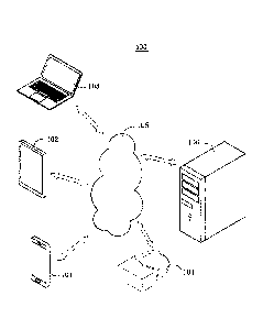
[0044] FIG. 1 is an architectural diagram illustrating an example system
to which
the present disclosure can be applied.
[0045] FIG. 2 is a schematic structural diagram illustrating an
implementation of a
photography-based 3D modeling system according to the present disclosure.
[0046] FIG. 3 is a schematic structural diagram illustrating another
implementation
of a photography-based 3D modeling system according to the present disclosure.
[0047] FIG. 4 is a schematic flowchart illustrating an implementation of
a
photography-based 3D modeling method according to the present disclosure.
[0048] FIG. 5 is a schematic structural diagram illustrating an
implementation of
an automatic 3D modeling apparatus according to the present disclosure.
[0049] FIG. 6 is a schematic structural diagram illustrating another
implementation
of an automatic 3D modeling apparatus according to the present disclosure.
[0050] FIG. 7 is a schematic flowchart illustrating an implementation of an
automatic 3D modeling method according to the present disclosure. and
[0051] FIG. 8 is a schematic structural diagram illustrating an
implementation of
an electronic device according to the present disclosure.
[0052] With reference to the accompanying drawings and specific
implementations,
12
Date Recue/Date Received 2020-12-15
the above and other features, advantages and aspects of implementations of the
present
disclosure become clearer. Same or similar reference numerals in the
accompanying
drawings represent same or similar elements. It should be understood that the
accompanying drawings are examples, components and elements are not
necessarily
drawn to scale.
DETAILED DESCRIPTION
[0053] Unless otherwise defined, the technical and scientific terms used
in this
specification have the same meanings as those commonly understood by a person
.. skilled in the art of the present disclosure. The terms used in the
specification of the
present application are merely intended for the purpose of describing the
specific
implementations, but not intended to limit the present disclosure. The terms
"include"
and "have" and any other variants thereof in the specification, the claims,
and the
accompanying drawings of the present disclosure are intended to cover non-
exclusive
inclusion. In the specification and the claims, or the accompanying drawings
of the
present disclosure, the terms "first", "second", and the like are intended to
distinguish
between different objects but do not indicate a particular order.
[0054] Mentioning an "implementation" in the specification means that a
particular
characteristic, structure, or feature described with reference to the
implementation can
be included in at least one implementation of the present disclosure. The word
appearing in various locations in the specification does not necessarily refer
to the same
implementation, and is not an independent or alternate implementation
exclusive of
other implementations. It is explicitly and implicitly understood by a person
skilled in
the art that the implementations described in the specification can be
combined with
another implementation.
[0055] To make a person skilled in the art understand the solutions in
the present
disclosure better, the following further describes the present disclosure with
reference
to the accompanying drawings and the implementations.
System Structure
13
Date Recue/Date Received 2020-12-15
[0056] A system structure in an implementation of the present disclosure
is first
described. As shown in FIG. 1, a system structure 100 can include mobile
devices 101,
102, 103, and 104, a network 105, and a server 106. The terminal devices 101,
102, 103,
and 104 and the server 106 are connected to one another via the network 105.
[0057] In the present implementation, the mobile device 101, 102, 103, or
104
shown in FIG. 1 can transmit various information through the network 105. The
network 105 can include various connection types, such as wired and wireless
communication links, or fiber optic cables. It should be noted that, the above
wireless
connection methods can include but are not limited to a 3G/4G/5G connection, a
Wi-Fi
connection, a Bluetooth connection, a WiMAX connection, a Zigbee connection, a
UVVB connection, a local area network ("LAN"), a wide area network ("WAN'), an
internetwork (for example, the Internet), an end-to-end network (for example,
ad hoc
end-to-end network), and other network connection methods that are currently
known
or will be developed in the future. The network 105 can communicate using any
.. network protocol that is currently known or will be developed in the
future, such as the
Hyper Text Transfer Protocol (HTTP), and can interconnect with digital and
data
communication, for example, a communications network, of any form or medium.
[0058] A user can use the mobile devices 101, 102, 103, and 104 to
interact with
the server 106 via the network 105. to receive or send messages, etc. Various
client
applications can be installed on the mobile device 101, 102, 103, or 104, such
as live
video and playback applications, web browser applications, shopping
applications,
search applications, instant messaging tools, email clients, social platforms
software,
etc.
[0059] The mobile device 101, 102, 103, or 104 may be any electronic
device that
has a touchscreen and/or supports web browsing, and has a photo capture
function,
including but not limited to mobile terminals such as a smartphone, a tablet
computer,
an e-book reader, a moving picture experts group audio layer-3 (MP3) player, a
moving
picture experts group audio layer-4 (MP4) player, a head-mounted display
device, a
notebook computer, a digital broadcast receiver, a personal digital assistant
(PDA), a
portable multimedia player (PMP) and an in-vehicle terminal, as well as a
digital TV, a
14
Date Recue/Date Received 2020-12-15
desktop computer, etc.
[0060] The server 106 may be a server that provides various services,
such as a
back-end server that supports 3D modeling on the mobile device 101, 102, 103,
or 104.
[0061] It should be understood that the quantities of mobile devices,
networks, and
.. servers in FIG. 1 are merely examples. Depending on implementation needs,
there can
be any quantities of mobile devices, networks, and servers.
[0062] Herein, the mobile device can be attached to a stand, such as a
tripod.
independently or jointly with another electronic terminal device such as a
camera, to
cooperate with applications running in the Android system to implement the
implementation method in the present disclosure, or to cooperate with
applications
running in other operating systems such as the iOS system, the Windows system,
and
HarmonyOS to implement the implementation method in the present disclosure.
Photography-based 3D Modeling System
[0063] FIG. 2 is a schematic structural diagram illustrating an
implementation of a
photography-based 3D modeling system according to the present disclosure. As
shown
in FIG. 2, the photography-based 3D modeling system in the present
implementation
includes: a photo capture unit 201, configured to capture a first image of
each of
multiple spaces. Herein, the first image may be, for example, an image used
for 3D
modeling, including an ordinary photo, a panoramic photo, and a processed (for
example, undistorted) panoramic photo. The photo capture unit 201 can be
implemented by a photo capture module in the mobile device.
[0064] Herein, the photo capture unit 201 can capture multiple second
images when
moving among the spaces. Herein, the second images may be, for example, images
used
for positioning, including an ordinary photo, a panoramic photo, and a
processed (for
example, undistorted) panoramic photo. Herein, the first image and the second
image
may be the same image, partially identical images, or different images, which
is not
limited. The image used for positioning herein may also be a photo, a preview
image, a
video frame, etc., captured by the photo capture unit 201, and may be stored
or may be
not stored but used only to identify and match feature points.
Date Recue/Date Received 2020-12-15
[0065] Herein, for example, the photo capture unit 201 has a positioning
sensor and
a direction sensor, and can obtain positioning information and direction
information
when capturing an image used for 3D modeling of the space in which the photo
capture
unit 201 is located. Here, the positioning sensor may be, for example, one or
more of
an acceleration sensor, a gyroscope, a linear acceleration sensor, an angular
velocity
sensor, a gravity sensor, and the like. The direction sensor may be, for
example, one or
more of a direction sensor, a magnetic sensor, and the like.
[0066] A 3D model generation unit 202 is configured to generate a 3D
model of
each space based on the image used for 3D modeling that is captured by the
photo
capture unit 201 for each space.
[0067] In one or more implementations, for example, the photo capture
unit 201
has binocular lenses, and the binocular lenses separately capture the images
used for
3D modeling at the same photo capture point; and the 3D model generation unit
202
compares the images used for 3D modeling that are captured by the binocular
lenses,
determines corresponding pixels, and obtains depth information of each
corresponding
pixel, so as to generate the 3D model.
[0068] Certainly, in one or more implementations, for example, the 3D
model
generation unit 202 can further predict a depth of each pixel or depths of
some pixels
in the image used for 3D modeling by using a deep learning method, and
calculate a
normal direction of each pixel or normal directions of some pixels or predict
the normal
direction of each pixel or the normal directions of some pixels by directly
using the
deep learning method, so as to generate a 3D model of each space.
[0069] Herein, in one or more implementations, the method for predicting
the depth
of each pixel in the image used for 3D modeling or predicting the normal
direction of
each pixel by using the deep learning method may be, for example, a method for
training a plane-aware convolutional neural network by predicting a dense
depth, a
surface normal, and a plane boundary from a single indoor 360 image (for
example,
refer to Pano Popups: Indoor 3D Reconstruction with a Plane-Aware Network); or
a
method for predicting a depth from a 360 image through end-to-end learning by
using
a large-scale three-dimensional dataset, for example, using an approach as
described in
16
Date Recue/Date Received 2020-12-15
OmniDepth: Dense Depth Estimation for Indoors Spherical Panoramas or other
suitable
approaches.
[0070] A capture position acquisition unit 203 is configured to obtain
position and
capture direction information of the photo capture unit 201 when capturing the
image
used for 3D modeling of each space, and certainly can further obtain a focal
length of
the lens, a scanning interval of the lens, and other parameters that can
affect image
content capture, for example, settings for a focal length, a wide-angle lens,
or a
telephoto lens. If these parameters are incorrect, identification or relative
sizes of
image content features may be incorrect).
[0071] Herein, for example, the capture position acquisition unit 203 can
perform
feature point matching based on images at adjacent photo capture points among
the
multiple images used for positioning that are captured by the photo capture
unit 201, to
obtain relative displacement and capture direction information of each photo
capture
point, for example, can build a tracking map that includes all photo capture
points in
the same coordinate system, so as to obtain position and capture direction
information
of the photo capture unit 201 when capturing the image used for 3D modeling of
the
space in which the photo capture unit 201 is located.
[0072] Herein, for example, the capture position acquisition unit 203 can
further
obtain, based on positioning information and direction information provided by
the
photo capture unit 201 when capturing an image used for 3D modeling of a space
in
which the photo capture unit 201 is located, position and capture direction
information
of the photo capture unit 201 when capturing the image used for 3D modeling of
the
space in which the photo capture unit 201 is located.
[0073] Herein, the capture position acquisition unit 203 further corrects
the tracking
map formed by relative displacement and capture direction information based on
displacement information such as acceleration information and velocity
information or
other action/motion information provided by sensors of the photo capture unit
201,
including a displacement sensor such as an acceleration sensor or a velocity
sensor, and
a gyroscope, a barometric pressure sensor or another motion sensor.
[0074] A 3D model assembling unit 204 is configured to: based on the
position and
17
Date Recue/Date Received 2020-12-15
capture direction information of each space obtained by the capture position
acquisition
unit 203, assemble the 3D models of the spaces generated by the 3D model
generation
unit 202 in the global three-dimensional coordinate system, to generate an
overall 3D
model from the individual 3D models of the spaces.
[0075] Herein, the 3D model assembling unit 204 can further convert local
coordinates of the 3D model of a single room into global coordinates, for
example, by
using a transformation matrix based on the position and capture direction
information
obtained by the capture position acquisition unit 203 when each room is
captured, so as
to obtain the overall 3D model of all photo capture points.
[0076] Herein, the method for converting local coordinates of the 3D model
of a
single room into global coordinates includes: enabling the photo capture unit
201 to
move a predetermined distance, and obtaining, by the capture position
acquisition unit
203, coordinates of two endpoints of the predetermined distance (for example,
one
meter), where a ratio of a difference between the coordinates of the two
endpoints to
the predetermined distance is the scale of the local coordinates to the global
coordinates;
or estimating, by using a feature point identified by the capture position
acquisition unit
203, a ratio of a height of a plane on which a floor or a ceiling of the space
is located to
a height of the photo capture unit 201, to obtain the scale of the local
coordinates to the
global coordinates. Before performing photo capture at a first photo capture
point or
during movement of subsequent photo capture, the photo capture unit 201 moves
a
predetermined distance to obtain a predetermined quantity of the feature
points.
[0077] Herein, for example, the method for estimating the ratio of the
height of the
plane on which the floor or the ceiling of the space is located to the height
of the photo
capture unit 201 is projecting the photo capture point vertically onto the
floor plane,
.. and then connecting the feature points, e.g., on the floor, so that these
three points form
a triangle. Assume that the projection line is Li, the line from the photo
capture point
to the feature point is L2, and the line from the projection point to the
feature point is
L3. The angle between L1 and L2 is known, e.g., based on the characteristics
of the
panoramic image, Li can be calculated by using a trigonometric function based
on a
length of L3 and the above angle, and a scale is calculated based on an actual
height of
18
Date Recue/Date Received 2020-12-15
the camera.
[0078] Herein, the predetermined distance needs to satisfy a sufficient
distance to
obtain a predetermined quantity of feature points.
[0079] Specifically, in one or more implementations, for example, the
photo capture
unit 201 uses a camera or a mobile phone camera only. Because obtained
coordinates
are all relative values, the coordinates need to be converted into absolute
values. In
other words, an image comparison algorithm usually has no accurate scale. The
coordinates are relative and have no specific size. As a result, displacement
and scales
calculated from different pictures are inconsistent, causing misalignment.
During actual
implementation, the above method for converting the coordinates may be as
follows:
(a) making a user move a specified distance, for example, one meter, and
obtaining coordinates of two endpoints of the movement distance, where a ratio
of a
difference between the coordinates of the two endpoints to the movement
distance is
the scale of local coordinates to global coordinates; and
(b) estimating, based on a feature point identified by the system, a plane on
which a floor or a ceiling of a room is located. Assume that a vertical
coordinate axis in
the coordinate system is a z-axis, and an equation of the plane is z = a.
Because the
height of the photo capture unit 201 is known, or a height from the photo
capture unit
201 to a ceiling is known, which is h, a/h is the scale of the local
coordinates to the
global coordinates. Herein, because a specific quantity of feature points on
the same
plane, e.g., floor or ceiling, need to be identified to estimate a value of a,
an initialization
process can be used during implementation, that is, moving a sufficiently long
distance,
for example, more than two meters, so that adequate feature points can be
accumulated
in different environments. The initialization process can be performed prior
to the first
photo capture point. If the initialization fails, it can be performed again
without
affecting subsequent photo capture. Alternatively, the initialization process
can be
performed during movement among subsequent photo capture points.
[0080] In the present implementation, for example, the photo capture unit
201 can
be implemented by a camera and/or a mobile phone with a photo capture
function.
[0081] In one or more implementations, for example, the camera and the
mobile
19
Date Recue/Date Received 2020-12-15
phone with a photo capture function for implementing the photo capture unit
201 can
be attached to attached to the same camera stand; and during movement of the
stand,
multiple images used for positioning captured by the camera or the mobile
phone with
a photo capture function are obtained, so as to obtain position and capture
direction
information of the camera or the mobile phone with a photo capture function
when
capturing the image used for 3D modeling of the space in which the camera or
the
mobile phone is located.
[0082] Herein, based on a positioning system of the camera or the mobile
phone
with a photo capture function, the images used for positioning captured by the
camera
or the mobile phone with a photo capture function can be further used, and
feature point
matching can be performed based on images used for positioning at adjacent
photo
capture points to obtain relative displacement and capture direction
information of each
photo capture point, thereby providing a relative position and direction of
each photo
capture point.
[0083] In one or more implementations, because a position, a direction and
a
tracking map of the photo capture point are obtained through the mobile phone,
and
because the camera can be attached to the top of the camera stand by using a
screw, the
angle between the camera and the mobile phone may be different for each
mounting,
but the angle remains unchanged during the photo capture of a house. The 3D
model of
an individual room needs to be rotated by this angle, and then put into the
global
coordinates based on a position and a capture direction obtained by the mobile
phone,
to generate an overall 3D model.
[0084] Herein, before capturing the image used for 3D modeling of the
first space
or during movement of subsequent photo capture, the photo capture unit 201 can
obtain
an angle between a capture direction of a lens of the camera and a capture
direction of
the mobile phone by using one or more of the following methods:
herein, the capture direction of the lens of the camera may be a direction of
one of two fisheye lenses, e.g., front and rear, of a common panoramic camera,
or may
be a direction of a lens for capturing the first photo by a panoramic camera
that captures
multiple photos by rotating one lens;
Date Recue/Date Received 2020-12-15
(1) simultaneously running a positioning system based on the mobile phone
and a positioning system based on the camera, and moving the stand by a
specific
distance; in such case, the two systems each provide one displacement vector,
and an
angle between the two vectors is the angle between the capture direction of
the lens of
the camera and the capture direction of the mobile phone;
(2) specifying an angle consistent with the capture direction of the mobile
phone by manually rotating a preview image or a captured image of the camera;
(3) matching preview images or captured images of the mobile phone and
the camera by using an image recognition algorithm, to identify the angle;
herein, a
possible implementation method for identifying the angle may include at least
one of
the following ways:
calculating feature points in the images captured by the mobile phone and
the camera. For example, use scale-invariant feature transform (SIFT) to find
a position
difference of the matching feature points in the two images, in order to
calculate the
angle between capture directions of two lenses; or
building visual simultaneous localization and mapping (VSLAM) systems
respectively by using video streams captured by the two lenses, where the
angle
between displacement of the cameras in the two systems is the angle between
the
capture directions of the lenses;
(4) using an additional mark (including adding a mark to the stand to form
a known fixed angle with a mounting direction of the mobile phone), and then
identifying the mark in the preview image or the image of the camera, so as to
calculate
the angle between the capture direction of the lens of the camera and the
capture
direction of the mobile phone; and
(5) using a camera installation interface on the stand so that a known fixed
angle is formed between the camera and the mobile phone (mobile device).
[0085] Certainly, herein, the position, the direction and the tracking
map of the
photo capture point can also be calculated from the camera images. In such
case, the
calculation of the 3D model does not depend on the angle between the camera
and the
mobile phone. In this case, the mobile phone does not need to be attached to
the stand.
21
Date Recue/Date Received 2020-12-15
[0086] Herein, if the camera also has a direction sensor, the angle can
be calculated
by directly obtaining the directions of the camera and the mobile phone.
[0087] The 3D model generation unit 202 is implemented by the mobile
phone or
by a remote server; when being implemented by the remote server, the 3D model
generation unit receives, through a network, one or more images used for 3D
modeling,
and/or one or more images used for positioning that are captured and sent by
the camera
and/or the mobile phone with a photo capture function, and/or information
obtained by
one or more motion sensors, to generate a 3D model of each space.
[0088] For example, the capture position acquisition unit 203 can be
implemented
by the camera or the mobile phone.
[0089] For example, the 3D model assembling unit 204 can be implemented
by the
mobile phone or by a remote server; when being implemented by the remote
server, the
3D model assembling unit 204 receives, through a network, the position and
capture
direction information of each space sent by the capture position acquisition
unit 203,
completes the assembling processing based on the position and capture
direction
information, and sends the generated overall 3D model to the mobile phone or
another
device. FIG. 3 is a schematic structural diagram illustrating another
implementation of
a photography-based 3D modeling system according to the present disclosure. As
shown in FIG. 3, in the photography-based 3D modeling system in the present
implementation, for example, a photography-based 3D modeling space is a room,
and
an image used for 3D modeling is an indoor image of the room. The photography-
based
3D modeling system includes the following:
a photo capture unit 301, configured to capture an image used for 3D
modeling of each of multiple rooms.
[0090] Herein, the photo capture unit 301 can capture multiple images used
for
positioning when moving among the rooms.
[0091] Herein, for example, the photo capture unit 301 has a positioning
sensor and
a direction sensor, and can obtain positioning information and direction
information
when capturing an image used for 3D modeling of the room in which the photo
capture
unit 301 is located.
22
Date Recue/Date Received 2020-12-15
[0092] A 3D model generation unit 302 is configured to generate a 3D
model of
each room based on the image used for 3D modeling that is captured by the
photo
capture unit 301 for each room.
[0093] Herein, the 3D model generation unit 302 identifies one or more
image areas
of at least one of a floor, a ceiling, and a wall in the image used for 3D
modeling based
on a deep learning method; divides the identified image area(s) into blocks
based on an
image processing technology, where each block is approximately considered as
one
plane, image blocks of the floor and the ceiling are located on a horizontal
plane, and
an image block of the wall is located on a vertical plane; and generates the
3D model
by solving an equation for each plane, where for two planes that intersect in
the image
used for 3D modeling, an error between a calculated intersecting line and an
actually
observed intersecting line is minimized.
[0094] Herein, the 3D model generation unit 302 further uses a computer
vision
algorithm to identify wall corners in the indoor image and connect the wall
corners to
generate a rough model of the room.
[0095] Herein, in one or more implementations, for example, the method
for
identifying wall corners in the image may be using the self-supervised
training
framework of interest point detection and description, for example, using an
approach
as described in SuperPoint: Self-Supervised Interest Point Detection and
Description or
other suitable approaches, and then connecting the wall corners to generate a
rough
model of the room, so as to capture a geometric relationship between objects
such as
wall corners that frequently appear in the same three-dimensional space
structure.
[0096] A capture position acquisition unit 303 is configured to obtain
position and
capture direction information of the photo capture unit 301 when capturing the
image
used for 3D modeling of each room.
[0100] Herein, for example, the capture position acquisition unit 303 can
perform
feature point matching based on images at adjacent photo capture points among
the
multiple images used for positioning that are captured by the photo capture
unit 301, to
obtain relative displacement and capture direction information of each photo
capture
point, for example, can build a tracking map that includes all photo capture
points in
23
Date Recue/Date Received 2020-12-15
the same coordinate system, so as to obtain position and capture direction
information
of the photo capture unit 301 when capturing the image used for 3D modeling of
the
room in which the photo capture unit 301 is located.
[0101] Herein, for example, the capture position acquisition unit 303 can
further
obtain, based on positioning information and direction information provided by
the
photo capture unit 301 when capturing an image used for 3D modeling of a room
in
which the photo capture unit 301 is located, position and capture direction
information
of the photo capture unit 301 when capturing the image used for 3D modeling of
the
room in which the photo capture unit 301 is located.
[0102] Herein, the capture position acquisition unit 303 further corrects
the tracking
map based on acceleration information and velocity information provided by an
acceleration sensor and a velocity sensor of the photo capture unit 301.
[0103] A 3D model assembling unit 304 is configured to: based on the
position and
capture direction information of each room obtained by the capture position
acquisition
unit 303, assemble the 3D models of the rooms generated by the 3D model
generation
unit 302 in the global three-dimensional coordinate system, to generate an
overall 3D
model from the individual 3D models of the rooms.
[0104] Herein, the 3D model assembling unit 304 can further convert local
coordinates of the 3D model of a single room into global coordinates, for
example, by
using a transformation matrix based on the position and capture direction
information
obtained by the capture position acquisition unit 303 when each room is
captured, so as
to obtain the overall 3D model of all photo capture points.
[0105] Herein, the 3D model assembling unit 304 can perform a correction
on 3D
models of the multiple rooms, including correcting wall line directions of all
rooms by
using a statistical method. For indoor scenes, in most cases, walls of each
room meet
the parallel and vertical relationships. By finding an average or median of
the wall line
directions of each room, or using algorithms such as Random Sample Consensus
(RANSAC) to identify the most possible wall line direction, the rooms with
errors
within a specific range are adjusted to the same direction, so that wall lines
of all rooms
are made parallel if they were within a specific error range prior to
correction.
24
Date Recue/Date Received 2020-12-15
[0106] Herein,
when assembling the 3D models of the rooms, the 3D model
assembling unit 304 can further correct one or more overlapping parts and/or
gaps.
Herein, the correction method may include at least one of the following ways:
[0107] Assuming
that the position of the room is accurate, but there is an error in
outline recognition, the overlapping part is trimmed and the gap is filled.
[0108] Assuming
that the outline of the room is recognized accurately, but there is
an error in the position, the position of each room is moved to eliminate the
overlap and
the gap as far as possible.
[0109]
Certainly, in practice, the two methods can be performed repeatedly and
.. iteratively to get close to the real situation.
[0110] A 2D
floorplan generation unit 305 is configured to generate a 2D floorplan
in the following ways:
1. projecting each surface of the generated 3D model onto a plane parallel
to the floor, and merging these projections into a polygon;
2. correcting and simplifying the obtained polygon, which may include, for
example, the following methods:
(1) retaining only main vertices of the polygon and deleting small concave
or convex rectangles; for example, concave or convex rectangles less than the
standard
wall thickness, e.g., 12 cm or 24 cm, can be deleted; and
(2) using a computer vision algorithm to detect straight lines in the picture,
and then determining the direction of a wall, and aligning edges that are
approximately
parallel or perpendicular to the direction of the wall to corresponding
directions;
certainly, the obtained polygon can be corrected and simplified in other ways,
which is not limited to the above approaches;
3. assembling the generated 2D floorplans of the rooms in the same two-
dimensional coordinate system based on the position and capture direction
information
of each room obtained by the capture position acquisition unit 303, to
generate an
overall 2D floorplan from the individual 2D floorplans of the rooms; and
4. identifying and marking a position of a door and/or a window, including
identifying the position of the door and/or the window on the indoor image by
using a
Date Recue/Date Received 2020-12-15
deep learning method, or determining the position of the door by finding where
a room
outline is crossed by the track of the tracking map from capturing the first
images of
multiple rooms of the same property by the photo capture unit 301.
[0111] Herein, in one or more implementations, for example, the method
for
identifying the position of the door and/or the window on the indoor image by
using the
deep learning method may be detecting each target object such as the door
and/or the
window by using YOLO (You Only Look Once: Unified, Real-Time Object
Detection).
[0112] Herein, the 2D floorplan generation unit 305 can further correct
2D
floorplans of the multiple rooms, including correcting wall line directions of
all the
rooms by using a statistical method, so that wall lines of all the rooms are
aligned in the
same direction if they were parallel within a specific error range. Herein,
the uniform
correction method may be the same as that described above, and details are
omitted for
simplicity.
[0113] Herein, when assembling the 2D floorplans of the rooms, the 2D
floorplan
generation unit 305 can further correct one or more overlapping parts and/or
gaps.
[0114] Herein, the 2D floorplan generation unit can further generate a 2D
floorplan
in the following ways:
1. projecting each surface of the overall 3D model generated by the 3D
model assembling unit 304 onto a plane parallel to the floor, and merging
these
projections into one or more polygons;
2. correcting and simplifying the obtained polygon(s), which may include,
for example, the following methods:
(1) retaining only main vertices of the polygon and deleting small concave
or convex rectangles; and
(2) using a computer vision algorithm to detect straight lines in the picture,
and then determining the direction of a wall, and aligning edges that are
approximately
parallel or perpendicular to the direction of the wall to corresponding
directions;
certainly, the obtained polygon can be corrected and simplified in other ways,
which is not limited to the above approaches; and
3. identifying and marking a position of a door and/or a window, including
26
Date Recue/Date Received 2020-12-15
identifying the position of the door and/or the window on the indoor image by
using a
deep learning method, or determining the position of the door by finding where
a room
outline is crossed by the track of the tracking map from capturing the first
images of
multiple rooms of the same property by the photo capture unit 301.
[0115] Herein, in one or more implementations, for example, the method for
identifying the position of the door and/or the window on the indoor image by
using the
deep learning method may be YOLO (You Only Look Once: Unified, Real-Time
Object
Detection).
Photography-based 3D Modeling Method
[0116] FIG. 4 is a schematic flowchart illustrating a photography-based
3D
modeling method according to the present disclosure.
[0117] Referring to FIG. 4, the photography-based 3D modeling method
provided
in the present disclosure includes the following steps:
[0118] (Si) attaching a mobile device (including a mobile phone, a tablet
computer,
etc.) with a photo capture function and/or a camera (including a panoramic
camera, a
fisheye camera, and an ordinary digital camera) to the same camera stand
(including a
tripod).
[0119] (S2) Obtaining multiple images used for positioning from the
camera or the
mobile device during movement of the stand, and obtaining a position and a
capture
direction of each photo capture point by using an image processing algorithm
and/or
one or more sensors of the camera or the mobile device, to build a tracking
map that
uses a global coordinate system.
[0120] Herein, step S2 uses a positioning system of the mobile device or
the camera
and performs feature point matching based on second images captured by the
mobile
device or the camera at adjacent photo capture points, to identify relative
displacement
and capture direction information of the photo capture points, in order to
build a
tracking map that includes all photo capture points in the same coordinate
system and
provides a position and a direction of each photo capture point.
[0121] Herein, step S2 further includes correcting the tracking map from
obtaining
27
Date Recue/Date Received 2020-12-15
information that includes acceleration, velocity, and direction of movement by
using
one or more sensors of the mobile device or the camera.
[0122] Herein, step S2 further includes obtaining an angle between a
capture
direction of a lens of the camera and a capture direction of the mobile
device, where at
an initialization stage, the positioning system based on the mobile device and
the
positioning system based on the camera run simultaneously, and the stand is
moved by
a specific distance; in such case, the two systems each provide one
displacement vector,
and an angle between the two vectors is the angle between the capture
direction of the
lens of the camera and the capture direction of the mobile device; an angle
consistent
with the capture direction of the mobile device is specified by manually
adjusting the
camera and the mobile device to angles with consistent orientation, for
example, by
rotating a preview image or a captured image of the camera; preview images or
captured
images of the mobile device and the camera are matched by using an image
recognition
algorithm, to identify the angle; or an additional mark is used (including
adding a mark
to the stand to form a fixed angle with a mounting direction of the mobile
device), and
then the mark is identified in the preview image or the image of the camera,
so as to
calculate the angle between the capture direction of the lens of the camera
and the
capture direction of the mobile device.
[0123] (S3) Generating 3D models on the mobile device or a remote server
by using
a deep learning algorithm or other methods based on an image used for 3D
modeling
that is captured at each photo capture point, to obtain a 3D model and/or a 2D
floorplan
of each photo capture point.
[0124] Herein, step S3 includes the following:
(S31) identifying one or more image areas of at least one of a floor, a
ceiling,
and a wall in the image based on a deep learning method; and
(S32) dividing the identified image area(s) into blocks based on an image
processing technology, where each block is approximately considered as one
plane,
image blocks of the floor and the ceiling are located on a horizontal plane,
and an image
block of the wall is located on a vertical plane; and generating the 3D model
by solving
an equation for each plane, where for two planes that intersect in the image,
an
28
Date Recue/Date Received 2020-12-15
intersecting line of the two planes is used as a constraint, so that an error
between a
calculated intersecting line and an actually observed intersecting line is
minimized.
[0125] Herein, step S3 further includes: using a computer vision
algorithm to
identify wall comers in an indoor image, and connecting the wall corners to
generate a
rough model of a room. Herein, in one or more implementations, for example,
the
method for identifying wall comers in the image may be using the training
framework
of self-supervised interest point detection and description, for example,
using an
approach described in SuperPoint: Self-Supervised Interest Point Detection and
Description or other suitable approaches, and then connecting the wall corners
to
generate a rough model of the room, so as to capture a geometric relationship
between
objects such as wall comers that frequently appear in the same three-
dimensional space
structure.
[0126] (S4) Placing the individual 3D models of all photo capture points
in the
global three-dimensional coordinate system based on the position and the
capture
direction obtained in S2; connecting individual 3D models of multiple photo
capture
points to generate an overall 3D model and/or 2D floorplan of the multiple
photo
capture points; and correcting wall directions of all rooms and optimizing the
overlap (s)
and gap(s). In popular room types, rooms are usually composed of parallel
walls,
however, when generating a room model generated from a single photo capture
point,
.. wall that are actually parallel may have an error in their directions (non-
parallel); by
considering the wall directions of multiple rooms, a uniform direction is
identified and
the wall directions of all rooms are adjusted based on the uniform direction.
[0127] Herein, step S4 includes the following:
(S41) converting local coordinates of a 3D model of a single photo capture
point into global coordinates, for example, by using a transformation matrix
based on
the position and the capture direction of each photo capture point, so as to
obtain an
overall 3D model of all photo capture points;
(S42) performs a correction on the 3D models of multiple photo capture points,
including correcting wall line directions of all photo capture points by using
a statistical
method, so that wall lines of all rooms are aligned in the same direction if
they were
29
Date Recue/Date Received 2020-12-15
parallel within a specific error range; and
(S43) when assembling the 3D models of the photo capture points, correcting
one or more overlapping parts and/or gaps.
[0128] (S5) automatically generating a virtual roaming effect between
panoramic
images on the mobile device.
[0129] The following describes application of the photography-based 3D
modeling
method in the present implementation with reference to the photography-based
3D
modeling system.
I. Hardware system
[0130] In the present implementation, the mobile phone and the camera are
attached
to the same stand (including a tripod, etc.).
II. System initialization
[0131] In the present disclosure, one of the following two methods is
used to obtain
the capture position of each photo capture point and the capture direction of
the camera:
[0132] Method (1): Based on the positioning system of the mobile phone,
that is,
using the images (photos, videos or preview images) of the mobile phone,
feature point
matching is performed based on images at adjacent photo capture points to
identify
displacement of the photo capture points, and the sensors (including a
gyroscope, an
accelerometer, a compass, or other inertial sensors, etc.) of the mobile
device are
preferably used for correction, so as to build a tracking map and provide
positions and
directions of the photo capture points.
[0133] Method (2): Based on the positioning system of the camera, that
is, using
the images (photos, videos or preview images) of the camera, feature point
matching is
performed based on images at adjacent photo capture points to identify
displacement of
the photo capture points; preferably, continuous feature matching and
positioning are
performed with photo capture points centimeters or decimeters apart, with
corrections
done using sensor data (such as a gyroscope, an accelerometer, a compass,
etc.) of the
camera, so as to build a tracking map and provide positions and directions of
the photo
capture points.
[0134] Comparison of the two methods: Method (1) is based on the mobile
phone
Date Recue/Date Received 2020-12-15
system. Because the mobile phone has multiple sensors, it can often provide
absolute
coordinate information that is relatively accurate, and can measure an
absolute distance
between the photo capture points. However, this method requires an additional
initialization process prior to usage.
[0135] In method (2), because the camera often does not have good built-in
sensors,
it can provide only relative coordinates of the capture position. It does not
require
additional initialization to align the coordinate axis of the 3D model of a
single photo
capture point with the track generated; in addition, the capture path comes
around to
form a loop, this method may provide smaller positioning errors.
[0136] When method (1) is used, the coordinates provided by the mobile
phone are
based on the local coordinate system of the mobile phone (generally, one axis
points in
a direction pointing perpendicularly to the ground, and the other two axes
point in the
front-rear and left-right directions, respectively). However, the coordinate
system of the
3D model generated based on panoramic photos is based on the coordinate system
of
the camera. The coordinate axes of the mobile phone and the camera do not
align with
each other. To solve this problem, the system needs to be initialized manually
or
automatically. A manual or automatic method can be used:
[0137] Manual method: A user uses an additional measurement tool or adds
a mark
on a device such as the stand, or manually enters an angle between the capture
direction
of the lens of the camera and the capture direction of the mobile phone.
[0138] Automatic method: at the initialization stage method (1) and
method (2) are
performed simultaneously, and the device is moved by a specific distance,
preferably 1
to 3 meters. In such case, the two systems each can provide one system
displacement
vector, and an angle between the two vectors is the angle between the capture
direction
of the lens of the camera and the capture direction of the mobile phone.
III. Determining the position of a photo capture point and the capture
direction
[0139] After starting running, the above system can provide position and
capture
direction information of the photo capture unit.
IV. Generation of a 3D model for a single photo capture point
[0140] There are two conventional photography-based modeling methods, both
of
31
Date Recue/Date Received 2020-12-15
which have obvious disadvantages.
[0141] In conventional method (a), a camera that can record depth
information is
used to directly generate a 3D model. Such method relies on more complex
hardware,
resulting in higher equipment costs, and usually operated by professional
photographers.
As a result, this method has disadvantages for wide adoption.
[0142] In conventional method (b), two photos are captured respectively
at two
photo capture points that are close to each other. Preferably, continuous
feature
matching and positioning are performed with photo capture points centimeters
or
decimeters apart. Subsequently, Multi View Stereo (MVS) (for details, refer to
https://github.com/cdcseacave/openMVS) is utilized for modeling. The advantage
is
that the entire process is fully automatic without manual intervention.
However, there
are disadvantages.
[0143] Disadvantage 1: It is computation intensive, and as a result rapid
modeling
cannot be easily achieved on a mobile device. Photos usually need to be
uploaded to a
.. server (cloud/PC) to run modeling algorithms benefiting from stronger
computing
capacities.
[0144] Disadvantage 2: It is difficult to specify how far photo capture
points should
be apart from each other. If the photo capture points are too dense,
operations become
inconvenient and time-consuming. If photo capture points are selected simply
based on
unobstructed line of sight between two adjacent photo capture points or by
"feeling
right", modeling may fail, and no warning can be provided for users during
photo
capture.
[0145] To overcome the above disadvantages, the present disclosure uses
an
innovative method: To improve the timeliness of model generation and to
achieve a
WYSIWYG (What You See Is What You Get) experience, 3D model generation
typically only include room outlines (wall positions), without including
models of
furniture and decorations that are not essential to the room structure. To be
specific,
i. Areas such as a floor, a ceiling, a wall, and a roof in the image are
identified by using deep learning method. For a plane on which one of these
areas is
located, either its normal direction (as in the case of the floor and ceiling)
is known or
32
Date Recue/Date Received 2020-12-15
its normal is on a horizontal plane (as in the case of a wall).
ii. The image is divided into blocks by using image processing technology,
where each block can be approximately considered as one plane. For a block of
the
floor, the plane equation is known. Assuming that the y-axis is pointing up
vertically,
.. the equation of the block of the floor is y + 1 = 0. For a block of the
wall, the plane
equation is Ax + Cz + D = 0. For a block of the ceiling, the plane equation is
y + D = 0.
For other blocks, the plane equation is Ax + By + Cz + D = 0. The process of
generating
a 3D model is that of solving these plane equations. For two planes that
intersect in the
image, there is an intersecting line visible in the image. Using the
intersecting line as a
constraint, the above equation solving process can be changed into a problem
of
minimization, so that for the two planes that intersect, an error between a
calculated
intersecting line and an actually observed intersecting line is minimized.
iii. Other methods can also be used to model a scene. For example, in an
indoor scene, a computer vision algorithm can be combined with deep learning
to
identify wall corners in an image, and the wall corners can then be connected
to generate
a rough model of a room. Herein, in one or more implementations, for example,
the
method for identifying wall corners in the image may be using the training
framework
of self-supervised interest point detection and description (for example,
refer to
SuperPoint: Self-Supervised Interest Point Detection and Description), and
then
connecting the wall comers to generate a rough model of the room, so as to
capture the
geometric relationship between objects such as wall corners that frequently
appear in
the same three-dimensional space structure.
iv. A 2D floorplan is generated. After a 3D model of each photo capture point
is obtained, a floorplan can be further generated. This is especially useful
for
applications of indoor scenes where a floorplan is often desired. The method
is as
follows:
1. Project each surface of the 3D model onto a 2D top view plane.
2. Merge these projections into a large polygon.
3. Correct and simplify the obtained polygon, which may include, for
example, the following methods:
33
Date Recue/Date Received 2020-12-15
(a) The obtained polygon usually has a large quantity of points, and the
polygon can be simplified. Only the vertices of the polygon on the 2D
floorplan are
retained, and small concave or convex rectangles are deleted.
(b) For an indoor scene, a computer vision algorithm can be used to detect
straight lines in the picture, and which are then used to determine the
direction of a wall.
Edges that are approximately parallel or perpendicular to the direction of the
wall are
aligned to corresponding directions.
4. Identify a door and/or a window. For an indoor scene, the door and/or the
window need/needs to be marked on the 2D floorplan by using the following two
methods:
(a) The deep learning method is directly used to identify the position and
size of a door and/or a window in a panoramic image.
[0146] Herein, in one or more implementations, for example, the method
for
identifying the position and the size of the door and/or the window on the
indoor image
by using the deep learning method may be YOLO (You Only Look Once: Unified,
Real-
Time Object Detection).
(b) Because the positioning system based on the mobile phone or the camera
not only provides a position and a capture direction of each photo capture
point, but
also has a movement track of the camera for the entire photo capture process.
Where
the track crosses the room outline can positively identify the position of the
door.
V. Generation of 3D models and 2D floorplans for multiple photo capture
points
[0147] In step 4, a 3D model of each photo capture point is generated.
Coordinates
of the obtained 3D models are all relative coordinates with respect to the
photo capture
points. In order to assemble these models and to generate an overall 3D model
and a
2D floorplan, first, local coordinates of a single model are converted into
global
coordinates, for example, by using a transformation matrix based on a known
position
and capture direction of each photo capture point.
[0148] On top of the above, further corrections can be made to the model
and the
34
Date Recue/Date Received 2020-12-15
floorplan.
i. The line directions are often inaccurate when generating the model of an
individual photo capture point . After multiple points are captured, all photo
capture
points can be corrected collectively by using a statistical method such as
Random
Sample Consensus (RANSEC) to identify best line direction, so that wall lines
of all
the rooms are aligned in the same direction if they were parallel within a
specific error
range, that is, small inconsistencies of wall line directions can thus be
avoided.
ii. Due to errors introduced in model generation, there may be one or more
overlaps, gaps, etc. when 3D models and 2D floorplans of multiple photo
capture points
are placed next to each other. Overlaps can be automatically removed and gaps
can be
filled on the 2D floorplan.
VI. Timely showing of results
[0149] The above process can be performed automatically and entirely on a
mobile
phone. Following completion, 3D models, 2D floorplans and virtual roaming
become
readily available on the mobile phone, and can be uploaded to the cloud to be
shared
with others.
VII. Manual editing
[0150] Since errors may be introduced by the positioning system, the 3D
modeling
algorithm for a single photo capture point, and various phases of optimizing
the 3D
models/2D floorplans of multiple photo capture points, in order to obtain a 3D
model
with higher precision, the present disclosure allows a user to manually edit
the photo
capture result. Manual editing can be performed by using software-based review
and
.. editing tools.
Automatic 3D Modeling Apparatus
[0151] FIG. 5 is a schematic structural diagram illustrating an
implementation of
an automatic 3D modeling apparatus according to the present disclosure. As
shown in
.. FIG. 5, the automatic 3D modeling apparatus includes the following:
Date Recue/Date Received 2020-12-15
a 3D model generation unit 501, configured to: based on an image used for
3D modeling of each of multiple spaces included in a modeling object, generate
a 3D
model of each space; and
a 3D model assembling unit 502, configured to: based on position and
capture direction information when the image used for 3D modeling of each of
the
multiple spaces is captured, assemble the 3D models of the spaces generated by
the 3D
model generation unit 501 in the global three-dimensional coordinate system,
to
generate an overall 3D model from the individual 3D models of the spaces.
[0152] Herein, the 3D model assembling unit 502 can further convert local
coordinates of the 3D model of a single space into global coordinates, for
example, by
using a transformation matrix based on the position and capture direction
information,
so as to obtain the overall 3D model of all spaces.
[0153] FIG. 6 is a schematic structural diagram illustrating another
implementation
of an automatic 3D modeling apparatus according to the present disclosure. In
the
present implementation, for example, an automatic 3D modeling space is a room,
and
an image used for 3D modeling is an indoor image of the room.
[0154] As shown in FIG. 6, the present implementation includes a 3D model
generation unit 601, configured to: based on an image used for 3D modeling of
each of
multiple rooms included in a modeling object, generate a 3D model of each
room.
[0155] Herein, the 3D model generation unit 601 identifies one or more
image areas
of at least one of a floor, a ceiling, and a wall in the image used for 3D
modeling based
on a deep learning method; divides the identified image area(s) into blocks
based on an
image processing technology, where each block is approximately considered as
one
plane, image blocks of the floor and the ceiling are located on a horizontal
plane, and
an image block of the wall is located on a vertical plane; and generates the
3D model
by solving an equation for each plane, where for two planes that intersect in
the image
used for 3D modeling, an error between a calculated intersecting line and an
actually
observed intersecting line is minimized.
[0156] Herein, the 3D model generation unit 601 further uses a computer
vision
algorithm to identify wall corners in the indoor image and connect the wall
corners to
36
Date Recue/Date Received 2020-12-15
generate a rough model of the room. Herein, in one or more implementations,
for
example, the method for identifying wall corners in the image may be using the
training
framework of self-supervised interest point detection and description, for
example,
using an approach as described in SuperPoint: Self-Supervised Interest Point
Detection
and Description or other suitable approaches, and then connecting the wall
comers to
generate a rough model of the room, so as to capture a geometric relationship
between
objects such as wall comers that frequently appear in the same three-
dimensional space
structure.
[0157] A 3D model assembling unit 602 is configured to: based on position
and
capture direction information when the image used for 3D modeling of each of
the
multiple rooms is captured, assemble the individual 3D models of the rooms
generated
by the 3D model generation unit 601 in the global three-dimensional coordinate
system,
to generate an overall 3D model from the individual 3D models of the rooms.
[0158] Herein, the 3D model assembling unit 602 can further convert local
coordinates of the 3D model of a single room into global coordinates, for
example, by
using a transformation matrix based on the position and capture direction
information,
so as to obtain the overall 3D model of all rooms.
[0159] Herein, the 3D model assembling unit 602 can further correct 3D
models of
the multiple rooms, including correcting wall line directions of all rooms by
using a
statistical method, so that wall lines of all rooms are aligned in the same
direction if
they were parallel within a specific error range.
[0160] Herein, when assembling the 3D models of the rooms, the 3D model
assembling unit 602 can further correct one or more overlapping parts and/or
gaps.
[0161] A 2D floorplan generation unit 603 is configured to generate a 2D
floorplan
in the following ways:
1. projecting each surface of the generated 3D model onto a plane parallel
to the floor, and merging these projections into a polygon;
2. correcting and simplifying the obtained polygon, which may include, for
example, the following methods:
(1) retaining only main vertices of the polygon and deleting small concave
37
Date Recue/Date Received 2020-12-15
or convex rectangles; and
(2) using a computer vision algorithm to detect straight lines in the picture,
and then determining the direction of a wall, and aligning edges that are
approximately
parallel or perpendicular to the direction of the wall to corresponding
directions;
certainly, the obtained polygon can be corrected and simplified in other ways,
which is not limited to the above approaches;
3. assembling the generated 2D floorplans of the rooms in the same two-
dimensional coordinate system based on the position and capture direction
information,
to generate an overall 2D floorplan from the individual 2D floorplans of the
rooms; and
[0097] 4. identifying and marking a position of a door and/or a window,
including
identifying the position of the door and/or the window on the indoor image by
using a
deep learning method, or determining the position of the door by finding where
a room
outline is crossed by the track of the tracking map from capturing the first
images of
multiple rooms of the same property.
[0162] Herein, in one or more implementations, for example, the method for
identifying the position and the size of the door and/or the window on the
indoor image
by using the deep learning method may be YOLO (You Only Look Once: Unified,
Real-
Time Object Detection).
[0163] Herein,
the 2D floorplan generation unit 603 can further correct 2D
floorplans of the multiple rooms, including correcting wall line directions of
all the
rooms by using a statistical method, so that wall lines of all the rooms are
aligned in the
same direction if they were parallel within a specific error range.
[0164] Herein,
when assembling the 2D floorplans of the rooms, the 2D floorplan
generation unit 603 can further correct one or more overlapping parts and/or
gaps.
[0165] Herein, the 2D floorplan generation unit 603 can further generate a
2D
floorplan in the following ways:
1. projecting each surface of the overall 3D model generated by the 3D
model assembling unit 602 onto a plane parallel to the floor, and merging
these
projections into one or more polygons;
2. correcting and simplifying the obtained polygon(s), which may include,
38
Date Recue/Date Received 2020-12-15
for example, the following methods:
(1) retaining only main vertices of the polygon and deleting small concave
or convex rectangles; and
(2) using a computer vision algorithm to detect straight lines in the picture,
and then determining the direction of a wall, and aligning edges that are
approximately
parallel or perpendicular to the direction of the wall to corresponding
directions;
certainly, the obtained polygon can be corrected and simplified in other ways,
which is not limited to the above approaches; and
3. identifying and marking a position of a door and/or a window, including
identifying the position of the door and/or the window on the indoor image by
using a
deep learning method, or determining the position of the door by finding where
a room
outline is crossed by the track of the tracking map from capturing the first
images of
multiple rooms of the same property. For example, the specific method is using
the
above YOLO model. Details are omitted herein for simplicity.
Automatic 3D Modeling Method
[0166] FIG. 7 is a schematic flowchart illustrating an implementation of
an
automatic 3D modeling method according to the present disclosure. As shown in
FIG.
7, the automatic 3D modeling method includes the following:
[0167] 3D model generation step S71: based on an image used for 3D modeling
of
each of multiple spaces included in a modeling object, generate a 3D model of
each
space.
[0168] In the present implementation, for example, an automatic 3D
modeling
space is a room, and an image used for 3D modeling is an indoor image of the
room.
[0169] In the 3D model generation step S71, one or more image areas of at
least
one of a floor, a ceiling, and a wall in the image used for 3D modeling are
identified
based on a deep learning method; the identified image area(s) is divided into
blocks
based on an image processing technology, where each block is approximately
considered as one plane, image blocks of the floor and the ceiling are located
on a
horizontal plane, and an image block of the wall is located on a vertical
plane; and the
39
Date Recue/Date Received 2020-12-15
3D model is generated by solving an equation for each plane, where for two
planes that
intersect in the image used for 3D modeling, an error between a calculated
intersecting
line and an actually observed intersecting line is minimized.
[0170] In the 3D model generation step S71, a computer vision algorithm
is further
used to identify wall corners in the indoor image and the wall comers are
connected to
generate a rough model of the room. Herein, in one or more implementations,
for
example, the method for identifying wall corners in the image may be using the
training
framework of self-supervised interest point detection and description, for
example,
using an approach as described in SuperPoint: Self-Supervised Interest Point
Detection
and Description or other suitable approaches, and then connecting the wall
comers to
generate a rough model of the room, so as to capture a geometric relationship
between
objects such as wall comers that frequently appear in the same three-
dimensional space
structure.
[0171] 3D model assembling step S72: based on position and capture
direction
information when the image used for 3D modeling of each of the multiple rooms
is
captured, assemble the 3D models of the rooms generated in the 3D model
generation
step S71 in the global three-dimensional coordinate system, to generate an
overall 3D
model from the individual 3D models of the rooms.
[0172] Herein, in the 3D model assembling step S72, local coordinates of
the 3D
model of a single space can be further converted into global coordinates, for
example,
by using a transformation matrix based on the position and capture direction
information, so as to obtain the overall 3D model of all spaces.
[0173] 2D floorplan generation step S73: generate a 2D floorplan in the
following
ways:
1. projecting each surface of the generated 3D model onto a plane parallel
to the floor, and merging these projections into a polygon;
2. correcting and simplifying the obtained polygon, which may include, for
example, the following methods:
(1) retaining only main vertices of the polygon and deleting small concave
or convex rectangles; and
Date Recue/Date Received 2020-12-15
(2) using a computer vision algorithm to detect straight lines in the picture,
and then determining the direction of a wall, and aligning edges that are
approximately
parallel or perpendicular to the direction of the wall to corresponding
directions;
herein, the obtained polygon can be corrected and simplified in other ways,
which is not limited to the above approaches; and
3. assembling the generated 2D floorplans of the rooms in the same two-
dimensional coordinate system based on the position and capture direction
information,
to generate an overall 2D floorplan from the individual 2D floorplans of the
rooms; and
4. identifying and marking a position of a door and/or a window, including
identifying the position of the door and/or the window on the indoor image by
using a
deep learning method, or determining the position of the door by finding where
a room
outline is crossed by the track of the tracking map from capturing the first
images of
multiple rooms of the same property. For example, the specific method is using
the
above YOLO model. Details are omitted herein for simplicity.
10174] Herein, in the 2D floorplan generation step S73, 2D floorplans of
the
multiple rooms can be further corrected, including correcting wall line
directions of all
the rooms by using a statistical method, so that wall lines of all the rooms
are aligned
in the same direction if they were parallel within a specific error range.
10175] Herein, in the 2D floorplan generation step S73, when the 2D
floorplans of
the rooms are assembled, one or more overlapping parts and/or gaps can be
further
corrected.
10176] Herein, in the 2D floorplan generation step S73, a 2D floorplan
can be
further generated in the following ways:
1. projecting each surface of the overall 3D model generated in the 3D model
assembling step S72 onto a plane parallel to the floor, and merging these
projections
into one or more polygons;
2. correcting and simplifying the obtained polygon(s), which may include,
for example, the following methods:
(1) retaining only main vertices of the polygon and deleting small concave
or convex rectangles; and
41
Date Recue/Date Received 2020-12-15
(2) using a computer vision algorithm to detect straight lines in the picture,
and then determining the direction of a wall, and aligning edges that are
approximately
parallel or perpendicular to the direction of the wall to corresponding
directions;
certainly, the obtained polygon can be corrected and simplified in other ways,
which is not limited to the above approaches;
3. identifying and marking a position of a door and/or a window, including
identifying the position of the door and/or the window on the indoor image by
using a
deep learning method, or determining the position of the door by finding where
a room
outline is crossed by the track of the tracking map from capturing the first
images of
multiple rooms of the same property. For example, the specific method is using
the
above YOLO model. Details are omitted herein for simplicity.
Electronic Device
[0177] FIG. 8 is a schematic structural diagram illustrating an
electronic device (for
example, the mobile device or the server in FIG. 1) 800 that is suitable for
implementing
an implementation of the present disclosure. The electronic device in the
implementation of the present disclosure may be any mobile device in the above
system,
and be preferably a mobile device with a photo capture function. The
electronic device
is attached to a stand (such as a tripod) independently or jointly with
another electronic
terminal device such as a camera, to cooperate with application software
running in
various mobile operating systems to implement the implementation method in the
present disclosure. The electronic device shown in FIG. 8 is merely an
example, and
shall not impose any limitation on a function and an application scope of the
implementations of the present disclosure.
[0178] As shown in FIG. 8, the electronic device 800 can include a
processing
apparatus (such as a central processing unit and a graphics processing unit)
801 for
controlling an overall operation of the electronic device. The processing
apparatus can
include one or more processors for executing instructions to perform all or
some of the
steps of the above method. In addition, the processing apparatus 801 can
include one or
more modules to process interaction with other apparatuses or units.
42
Date Recue/Date Received 2020-12-15
[0179] A storage apparatus 802 is configured to store various types of
data. The
storage apparatus 802 can include various types of computer-readable storage
media or
a combination thereof For example, the storage apparatus 802 can be an
electrical,
magnetic, optical, electromagnetic, infrared, or semiconductor system,
apparatus, or
device, or any combination thereof More specific examples of the computer-
readable
storage media can include but are not limited to an electrical connection with
one or
more conducting wires, a portable computer disk, a hard disk, a random access
memory
(RAM), a read-only memory (ROM), an erasable programmable read-only memory
(EPROM or flash memory), an optical fiber, a portable compact disk read-only
memory
(CD-ROM), an optical storage device, a magnetic storage device, or any
suitable
combination of the above. In the present disclosure, the computer-readable
storage
medium may be any tangible medium containing or storing a program. The program
may be used by or in combination with an instruction execution system,
apparatus, or
device.
[0180] A sensor apparatus 803 is configured to perceive specified and
measured
information and convert the information into a usable output signal according
to a
specific rule. One or more sensors can be included. For example, the sensor
apparatus
803 can include an acceleration sensor, a gyroscope sensor, a magnetic sensor,
a
pressure sensor, or a temperature sensor, etc., which are used to detect
changes in the
on/off state, relative positioning, acceleration/deceleration, temperature,
humidity, and
light of the electronic device.
[0181] The processing apparatus 801, the storage apparatus 802, and the
sensor
apparatus 803 are connected to each other by using a bus 804. An input/output
(I/O)
interface 805 is also connected to the bus 804.
[0182] A multimedia apparatus 806 can include input devices such as a
touchscreen,
a touch pad, a keyboard, a mouse, a camera, and a microphone to receive an
input signal
from a user. Various input devices can cooperate with various sensors of the
sensor
apparatus 803 to complete a gesture operation input, an image recognition
input, a
distance detection input, etc. The multimedia apparatus 806 can further
include output
devices such as a liquid crystal display (LCD), a speaker, and a vibrator.
43
Date Recue/Date Received 2020-12-15
[0183] A power supply apparatus 807 is configured to supply power to
various
apparatuses in the electronic device, and can include a power management
system, one
or more power supplies, and a component that distributes power to other
devices.
[0184] A communications apparatus 808 may allow the electronic device 800
to
perform wireless or wired communication with other devices to exchange data.
[0185] The above various apparatuses can also be connected to the I/O
interface
805 to implement application of the electronic device 800.
[0186] Although FIG. 8 shows the electronic device 800 having various
apparatuses,
it should be understood that not all shown apparatuses need to be implemented
or
included. More or fewer apparatuses can be implemented or included
alternatively.
[0187] In particular, according to the implementations of the present
disclosure, the
process described above with reference to the flowchart can be implemented as
a
computer software program. For example, the implementations of the present
disclosure include a computer program product that includes a computer program
that
is carried on a non-transient computer readable medium. The computer program
includes program code for performing the method shown in the flowchart. In
such an
implementation, the computer program can be downloaded and installed from a
network by using the communications apparatus, or installed from the storage
apparatus.
When the computer program is executed by the processing apparatus, the above
functions defined in the method in the implementations of the present
disclosure are
executed.
[0188] In the context of the present disclosure, a machine-readable
medium can be
a tangible medium, which can contain or store a program for use by or in
combination
with an instruction execution system, apparatus, or device.
[0189] It should be noted that, the above computer-readable medium in the
present
disclosure can be a computer-readable signal medium or a computer-readable
storage
medium, or any combination thereof In the present disclosure, the computer-
readable
signal medium can include a data signal that is propagated in a baseband or as
a part of
a carrier, and carries computer-readable program code. Such propagated data
signal
may take a plurality of forms, including but not limited to an electromagnetic
signal, an
44
Date Recue/Date Received 2020-12-15
optical signal, or any suitable combination of the above. The computer-
readable signal
medium may also be any computer-readable medium other than the computer-
readable
storage medium. The computer-readable signal medium may send, propagate, or
transmit a program for use by or in combination with an instruction execution
system,
apparatus, or device. The program code included in the computer-readable
medium can
be transmitted in any suitable medium, including but not limited to a cable,
an optical
cable, radio frequency (RF), or the like, or any suitable combination of the
above.
[0190] The above
computer-readable medium may be included in the above
electronic device, or may exist alone without being assembled into the
electronic device.
[0191] Computer
program code for performing an operation of the present
disclosure can be written in one or more program design languages or a
combination
thereof The above program design languages include but are not limited to
object-
oriented program design languages such as Java, Smalltalk, and C++, and
conventional
procedural program design languages such as C or a similar program design
language.
The program code can be executed entirely on a user computer, partly on a user
computer, as a separate software package, partly on a user computer and partly
on a
remote computer, or entirely on a remote computer or server. In a case
involving a
remote computer, the remote computer can be connected to a user computer
through
any type of network. Alternatively, the remote computer can be connected to an
external
computer (for example, by using an Internet service provider for connection
over the
Internet).
[0192] The
flowcharts and block diagrams in the accompanying drawings show the
architectures, functions, and operations that may be implemented according to
the
systems, methods, and computer program products in various implementations of
the
present disclosure. In this regard, each block in the flowchart or block
diagram may
represent one module, one program segment, or one part of code. The module,
the
program segment, or the part of code includes one or more executable
instructions for
implementing specified logical functions. It should also be noted that, in
some
alternative implementations, the functions marked in the blocks may occur in
an order
different from that marked in the figures. For example, two consecutive blocks
can
Date Recue/Date Received 2020-12-15
actually be executed in parallel, and sometimes they can also be executed in
reverse
order, depending on the function involved. It should also be noted that, each
block in
the block diagram and/or flowchart, and a combination of blocks in the block
diagram
and/or flowchart can be implemented by using a dedicated hardware-based system
that
performs a specified function or operation, or can be implemented by using a
combination of dedicated hardware and computer instructions.
[0193] The units described in the implementations of the present
disclosure can be
implemented by software or hardware. In some cases, a name of a unit does not
constitute a restriction on the unit.
[0194] The functions described above in the specification can be performed
at least
in part by one or more hardware logic components. For example, without
limitation,
exemplary types of hardware logic components that can be used include a field
programmable gate array (FPGA), an application-specific integrated circuit
(ASIC), an
application-specific standard product (ASSP), a system on chip (SoC), a
complex
programmable logic device (CPLD), etc.
[0195] The above descriptions are only the preferred implementations of
the present
disclosure and the explanation of the applied technical principles. A person
skilled in
the art should understand that, the disclosure scope of the present disclosure
is not
limited to the technical solutions formed by the specific combination of the
above
technical features, but should also cover other technical solutions formed by
any
combination of the above technical features or their equivalent features
without
departing from the above disclosed concepts, for example, a technical solution
formed
by interchanging the above features and the technical features that are
disclosed (but
not limited thereto) in the present disclosure having similar functions.
[0196] In addition, although the operations are depicted in a specific
order, it should
not be construed that these operations need to be performed in the specific
order shown
or sequentially. In a specific environment, multi-tasking and concurrent
processing may
be advantageous. Likewise, although some specific implementation details are
included
in the above discussion, these details should not be construed as a limitation
on the
.. scope of the present disclosure. Some features that are described in the
context of
46
Date Recue/Date Received 2020-12-15
separate implementations can also be implemented in combination in a single
implementation. Conversely, various features that are described in the context
of a
single implementation can also be implemented in multiple implementations
separately
or in any suitable sub-combination.
[0197] Although the subject matter has been described in languages specific
to
structural features and/or methodological logical actions, it should be
understood that
the subject matter defined in the appended claims is not necessarily limited
to the
specific features or actions described above. On the contrary, the specific
features and
actions described above are merely exemplary forms of the implementations.
[0198] The implementation can be further appreciated through the below
embodiments.
[0199] In an embodiments, an automatic 3D modeling apparatus includes a
3D
model generation unit, configured to: based on a first image of each of
multiple spaces
included in a modeling object, generate a 3D model of each space of the
multiple spaces;
and a 3D model assembling unit, configured to: based on position and capture
direction
information of the first image of each of the multiple spaces being captured,
assemble
3D models of the multiple spaces generated by the 3D model generation unit in
a global
three-dimensional coordinate system, to generate an overall 3D model from the
individual 3D models of the spaces.
[0200] The foregoing and other described embodiments can each, optionally,
include one or more of the following features:
[0201] A first feature, combinable with any of the other features,
specifies that the
3D model assembling unit converts local coordinates of the 3D model of a
single space
into global coordinates based on the position and capture direction
information, so as
to obtain the overall 3D model of all the spaces.
[0202] A second feature, combinable with any of the other features,
specifies that
the space is a room; the first image is an indoor image of the room; the 3D
model
generation unit identifies one or more image areas of at least one of a floor,
a ceiling,
and a wall in the first image based on a deep learning method; divides the
identified
image area(s) into blocks based on an image processing technology, wherein
each block
47
Date Recue/Date Received 2020-12-15
is approximately considered as one plane, image blocks of the floor and the
ceiling are
located on a horizontal plane, and an image block of the wall is located on a
vertical
plane; and generates the 3D model by solving an equation for each plane,
wherein for
two planes that intersect in the first image, an error between a calculated
intersecting
line and an actually observed intersecting line is minimized; and the 3D model
generation unit further uses a computer vision algorithm to identify wall
corners in the
indoor image and connect the wall corners to generate a rough model of the
room.
[0203] A third feature, combinable with any of the other features,
specifies that the
3D model assembling unit corrects 3D models of the multiple rooms, including
correcting wall line directions of all rooms by using a statistical method, so
that wall
lines of all rooms are aligned in the same direction if they were parallel
within a specific
error range; and when assembling the 3D models of the rooms, the 3D model
assembling unit corrects one or more overlapping parts and/or gaps.
[0204] A fourth feature, combinable with any of the other features,
specifies that
the automatic 3D modeling apparatus further comprises: a 2D floorplan
generation unit,
configured to generate a 2D floorplan in the following ways: projecting each
surface of
the generated 3D model onto a plane parallel to the floor, and merging these
projections
into a polygon; correcting and simplifying the obtained polygon, including at
least one
of the following: (1) retaining only main vertices of the polygon and deleting
small
concave or convex rectangles; and (2) using a computer vision algorithm to
detect
straight lines in the picture, and then determining the direction of a wall,
and aligning
edges that are approximately parallel or perpendicular to the direction of the
wall to
corresponding directions; assembling the generated 2D floorplans of the rooms
in the
same two-dimensional coordinate system based on the position and capture
direction
information, to generate an overall 2D floorplan from the individual 2D
floorplans of
the rooms; and identifying and marking a position of a door and/or a window,
including
identifying the position of the door and/or the window on the indoor image by
using a
deep learning method, or determining the position of the door by finding where
a room
outline is crossed by the track of the tracking map from capturing the first
images of
multiple rooms of the same property.
48
Date Recue/Date Received 2020-12-15
[0205] A fifth feature, combinable with any of the other features,
specifies that the
2D floorplan generation unit corrects 2D floorplans of the multiple rooms,
including
correcting wall line directions of all the rooms by using a statistical
method, so that wall
lines of all the rooms are aligned in the same direction if they were parallel
within a
specific error range; and when assembling the 2D floorplans of the rooms, the
2D
floorplan generation unit corrects one or more of overlapping parts and gaps.
[0206] A sixth feature, combinable with any of the other features,
specifies that the
automatic 3D modeling apparatus further comprises a 2D floorplan generation
unit,
configured to generate a 2D floorplan in the following ways: projecting each
surface of
the overall 3D model generated by the 3D model assembling unit onto a plane
parallel
to the floor, and merging these projections into one or more polygons;
correcting and
simplifying the obtained polygon(s), including at least one of the following:
(1)
retaining only main vertices of the polygon and deleting small concave or
convex
rectangles; and (2) using a computer vision algorithm to detect straight lines
in the
picture, and then determining the direction of a wall, and aligning edges that
are
approximately parallel or perpendicular to the direction of the wall to
corresponding
directions; and identifying and marking a position of a door and/or a window,
including
identifying the position of the door and/or the window on the indoor image by
using a
deep learning method, or determining the position of the door by finding where
a room
outline is crossed by the track of the tracking map from capturing the first
images of
multiple rooms of the same property.
[0207] In another embodiment, a photography-based 3D modeling method
comprises the following steps: attaching a mobile device with a photo capture
function
and a camera to a same camera stand; capturing a plurality of first images at
a plurality
of photo capture points using one or more of the mobile device and the camera;
obtaining multiple second images using the camera or the mobile device during
movement of the stand among the plurality of photo capture points; obtaining a
position
and a capture direction of each photo capture point by optionally using one or
more
sensors of one or more of the camera and the mobile device; building a
tracking map
that uses a global coordinate system based on the position of each photo
capture point;
49
Date Recue/Date Received 2020-12-15
generating 3D models on the mobile device or a remote server based on one or
more
first images captured at each photo capture point; placing the individual 3D
models of
all photo capture points in the global three-dimensional coordinate system
based on the
position and the capture direction of each photo capture point; and connecting
the
individual 3D models of multiple photo capture points to generate an overall
3D model
that includes multiple photo capture points.
[0208] The foregoing and other described embodiments can each,
optionally,
include one or more of the following features:
[0209] In a seventh feature, combinable with any of the other features,
specifies
that the steps use a positioning system of the mobile device or the camera and
performs
feature point matching based on second images captured by the mobile device or
the
camera at adjacent photo capture points, to identify relative displacement and
capture
direction information of the photo capture points, in order to build a
tracking map that
includes all photo capture points in the global coordinate system and provide
a position
and a direction of each photo capture point.
[0210] In an eighth feature, combinable with any of the other features,
specifies that
the method further comprises correcting the tracking map from obtaining
information
that includes acceleration, velocity, and direction of movement by using one
or more
sensors of the mobile device or the camera.
[0211] In a ninth feature, combinable with any of the other features,
specifies that
the method further comprises obtaining an angle between a capture direction of
a lens
of the camera and a capture direction of the mobile device, wherein at an
initialization
stage, the positioning system based on the mobile device and the positioning
system
based on the camera run simultaneously, and the stand is moved by a specific
distance;
in such case, the two systems each provide one displacement vector, and an
angle
between the two vectors is the angle between the capture direction of the lens
of the
camera and the capture direction of the mobile device; an angle consistent
with the
capture direction of the mobile device is specified by manually rotating a
preview image
or a captured image of the camera; preview images or captured images of the
mobile
device and the camera are matched by using an image recognition algorithm, to
identify
Date Recue/Date Received 2020-12-15
the angle; or an additional mark is used including adding a mark to the stand
to form a
fixed angle with a mounting direction of the mobile device, and then the mark
is
identified in the preview image or the image of the camera, so as to calculate
the angle
between the capture direction of the lens of the camera and the capture
direction of the
mobile device.
[0212] In a tenth feature, combinable with any of the other features,
specifies that
the generating the 3D models includes: identifying one or more image areas of
at least
one of a floor, a ceiling, and a wall in the image based on a deep learning
method; and
dividing the identified one or more image areas into blocks based on an image
processing technology, wherein each block is approximately considered as one
plane,
image blocks of the floor and the ceiling are located on a horizontal plane,
and an image
block of the wall is located on a vertical plane; and generating the 3D model
by solving
an equation for each plane, wherein for two planes that intersect in the
image, an
intersecting line of the two planes is used as a constraint, so that an error
between a
calculated intersecting line and an actually observed intersecting line is
minimized.
[0213] In an eleventh feature, combinable with any of the other features,
specifies
that the generating the 3D models further includes: using a computer vision
algorithm
to identify wall comers in an indoor image, and connecting the wall corners to
generate
a rough model of a room.
[0214] In a twelfth feature, combinable with any of the other features,
specifies that
the method further comprises: converting local coordinates of a 3D model of a
single
photo capture point into global coordinates based on a position and a capture
direction
of each photo capture point, so as to obtain an overall 3D model of all photo
capture
points; performing a correction on the individual 3D models of multiple photo
capture
.. points, including correcting wall line directions of all photo capture
points by using a
statistical method, so that wall lines of all rooms are aligned in the same
direction if
they were parallel within a specific error range; and when assembling the 3D
models of
the photo capture points, correcting one or more overlapping parts and gaps.
[0215] The various embodiments described above can be combined to provide
further embodiments. Aspects of the embodiments can be modified, if necessary
to
51
Date Recue/Date Received 2020-12-15
employ concepts of the various patents, applications and publications to
provide yet
further embodiments.
[0216] These and other changes can be made to the embodiments in light of
the
above-detailed description. In general, in the following claims, the terms
used should
not be construed to limit the claims to the specific embodiments disclosed in
the
specification and the claims, but should be construed to include all possible
embodiments along with the full scope of equivalents to which such claims are
entitled.
Accordingly, the claims are not limited by the disclosure.
52
Date Recue/Date Received 2020-12-15