Note : Les descriptions sont présentées dans la langue officielle dans laquelle elles ont été soumises.
CA 03104068 2020-12-16
WO 2019/245381 PCT/N02019/050127
1
Pipeline pulling tool and a method of actuating such a tool
This invention relates to a pulling tool used for pulling itself and other
equipment
into wellbores and pipelines and a method of actuating such a pipeline pulling
tool.
Wellbores and pipelines typically include long vertical and horizontal runs.
In many
wells there is a need for installing a fibre optic cable in order to obtain
real-time
measurements of flow, pressure, and temperature, among other things. In
itself, a
fibre optic cable is very thin and weak. Therefore, several types of claddings
are
used for protecting the fibre optic cable, such as metal, Kevlar, or carbon
rods.
Common to these cables are that they are very lightweight and a bit flexible,
which
present some challenges when they are to be installed in horizontal wells.
Other
elements that may be run into or out of wellbores and pipelines include
cables,
pipes, downhole packers, perforating guns, logging tools, bridge plugs, fibre
optic
cable, slick line, signal cables and other equipment used in a pipe or well.
When the pulling tool is to pull a fibre optic cable, the pulling tool must be
battery
operated because a fibre optic cable is a signal cable only and does not carry
electrical power. Therefore, it is essential that the pulling tool is as
efficient and
lightweight as possible to limit the necessary power consumption.
There is a need for a pulling tool for light well interventions that is able
to pull slick
line. Similarly to the case of a fibre optic cable, the same challenges are
encountered when it comes to being able to run a slick line into horizontal
wells.
Due to the limited rigidity of the slick line, it is not possible to push it
very far into
horizontal wells.
Wells in which there is a need for running light well interventions may have
small
internal diameters and include nipple profiles as small as 43 mm. It is
necessary,
therefore, to construct the pulling tool small enough to be able to pass
through the
smallest nipple profiles. The diameter of the well may be larger than the
combined
diameters of the pulling tool and the cable to be pulled by the pulling tool.
CA 03104068 2020-12-16
WO 2019/245381 PCT/N02019/050127
2
Several variants of pulling tools or well tractors are available in the
market. A
known solution includes an electric motor driving a hydraulic pump which in
turn
drives a hydraulic motor of the propulsion wheel. Such a system is technically
complex and not very efficient. Other variants available use an electric motor
that
transfers the rotation directly by way of an angular gear and on to the wheel
either
by way of chain/belt drive or straight gears.
It is often needed to perform intervention activities in curved and horizontal
wellbores and pipelines. In many cases it is desired to use wireline or slick
line to
carry out such operations. Thus, it is necessary to rely on gravity to get
into
vertical and curved wells. In order to reduce the friction against the
wellbore wall
and thereby be able to reach further in from vertical into curved wells, use
is
frequently made of friction-reducing roller wheel sections mounted on the tool
string and rolling on the wellbore wall. Exemplary tool strings run on
wireline or
slick line are tools for logging operations, tools for installing plugs, or
perforating
guns.
However, even when friction-reducing roller wheel sections are used it is
limited
how far into the well it is possible to reach by way of gravity.
It is therefore needed to install a section of a pulling tool in the tool
string in order
to be able to get further into curved and horizontal wells without
substantially
increasing the complexity.
Several variants of pulling tools or well tractors are available in the
market, but
those known are electric variants that depend on current-carrying cable. Thus,
more personnel and equipment are required in order to run such operations and
the whole operation becomes more expensive.
With the present invention a robust and efficient propulsion system is
obtained.
With this background, an invention has been made in which one pulling tool can
be efficiently and easily mounted between two friction-reducing roller wheel
CA 03104068 2020-12-16
WO 2019/245381 PCT/N02019/050127
3
sections in tool strings in order to reach further in from vertical into
curved and
horizontal wells.
As rolling wheels of friction-reducing roller sections are already available,
the
arrangement can be fitted with at least one propulsion wheel in a radial
direction of
the tool string. Through this invention, existing tool string solutions can be
pulled
further into the well in case of curved and horizontal wells.
The invention comprises a pulling tool having a tilting arm and a propulsion
wheel,
a battery section, an electronics control module, and a spring-loaded arm with
counting wheels. The pulling tool comprises at least one propulsion arm.
Another object of the invention is to be able to create a pulling tool which
is smaller
in diameter than the pulling tools existing in the market today.
With the present invention a small-sized, lightweight, high performance
propulsion
unit which is preferably powered by batteries is obtained.
Hence, the pulling tool with the propulsion section is mounted between two
friction-
reducing roller wheel sections. The pulling tool with the propulsion section
is
actuated as required based on given parameters.
In several cases during operations as described above a cable without a
current-
carrying conductor is involved, making it necessary to rely on a battery-
operated
pulling tool mounted in the tool string.
The present invention discloses a slick line, signal cable and/or fibre optic
cable
pulling wellbore and/or pipeline pulling tool including a propulsion module
having a
main section. A propulsion arm is hinged to the main section. The propulsion
arm
has a propulsion wheel. An electric motor for driving the propulsion wheel via
a
gear system is located in a hinged propulsion arm. In the present context, a
slick
line may also be an electric cable.
The pulling tool may further comprise a cable transition, a battery module
including
one or more batteries for powering the electric motor, an electronics module
and at
least one propulsion module.
CA 03104068 2020-12-16
WO 2019/245381 PCT/N02019/050127
4
The electric motor may be a brushless motor having a longitudinal axis
perpendicular to a rotation axis of the propulsion wheel, and the pulling tool
may
further comprise a controller for the brushless motor.
An electric actuator can be provided between the main section and the hinged
propulsion arm, whereby the hinged propulsion arm is configured for assuming a
first retracted position inside the propulsion module and a second actuated
position against a wellbore or pipeline wall.
The pulling tool may have an external diameter of less than 42 mm.
The invention further comprises a propulsion module of a pulling tool having a
main section and a propulsion arm hinged to the main section, the propulsion
arm
having a propulsion wheel with a gear system.
The pulling tool further comprises a controller for the brushless motor.
Hence, the invention comprises a pipeline pulling tool having an elongate
housing.
The pulling tool comprises a first roller wheel section having at least two
freely
rotating roller wheels extending out from a sidewall of the housing.
A second roller wheel section has at least two freely rotating roller wheels
extending out from a sidewall of the housing. A main section has a retractable
propulsion wheel and at least one actuator for actuating the propulsion wheel
between an extended position out from the sidewall of the housing and a
retracted
position inside the housing. The main section is located between the first
roller
wheel section and the second roller wheel section.
The pipeline pulling tool may further comprise a counting wheel section having
a
freely rotating counting wheel connected to a counter, supported in a
rotatably
supported tilting arm.
CA 03104068 2020-12-16
WO 2019/245381 PCT/N02019/050127
The pipeline pulling tool may comprise an attachment for a tool string in the
second roller wheel section.
The propulsion wheel may be driven by an electric motor, with the pipeline
pulling
5 tool further comprising a battery section for powering the electric
motor.
The pipeline pulling tool may further comprise an electronic control module
including sensors.
The sensors may include sensors for measuring, for example, ambient conditions
such as pressure, temperature, acceleration, flow, pipeline perforation,
transitions
between pipe sections, surface nature, inclination, acoustics/sound, tool
string
tension, and fluid parameters.
The electronic control module may control the advancement of the propulsion
wheel.
The pipeline pulling tool may further comprise a pressure equalization module.
The pressure equalization module comprises a unit for compensating volume
changes of oil internally in the housing surrounding the pulling tool. The oil
prevents water penetration. The volume changes are typically caused by
temperature changes changing the density of the oil and the volumes of the
housings.
All sections may be elongate and tubular.
Each of the first and second roller wheel sections may include four freely
rotating
roller wheels having rotation axes offset 45 relative to each other.
The first roller wheel section and the second roller wheel section may each
include
a separate cylindrical housing having a first diameter and the freely rotating
roller
wheels may have a diameter that is larger than the diameter of the cylindrical
CA 03104068 2020-12-16
WO 2019/245381 PCT/N02019/050127
6
housing, with the freely rotating roller wheels extending through the
cylindrical
housings.
The housing may be divided for each section and each section may form a module
so that each module constitutes a separate part which may be attached to an
adjacent module.
A tool string may be attached to the first roller wheel section, followed by
the
counting wheel section with a free-wheeling counting wheel, followed by a
pressure equalization section, followed by the main section with the
propulsion
wheel, followed by a control module, followed by a battery section, followed
by the
second roller wheel section.
In one embodiment, only one retractable propulsion wheel is located between
the
first roller wheel section and the second roller wheel section.
Each roller wheel may be supported by an axle and the axles of all roller
wheels
may be parallel, and the propulsion wheel and all roller wheels may be
situated in
the same plane.
Each of the first roller wheel section and second roller wheel section may
include
two wheels.
The main section with the propulsion wheel may be attached directly to the
second
roller wheel section.
The invention further includes a method of actuating a pipeline pulling tool
as
described above, wherein the main section of the pipeline pulling tool having
a
retractable propulsion wheel is put into operation without any control signals
from
a communication cable.
The method may further include putting the main section having a retractable
propulsion wheel into operation on the basis of a timing unit or a parameter
CA 03104068 2020-12-16
WO 2019/245381 PCT/N02019/050127
7
measured by one or more of an inclination sensor, a tool tension sensor, a
sensor
of a counting wheel section with a freely rotating counting wheel, an
acceleration
sensor, a pressure sensor, or a sensor recording internal geometry of the
pipeline.
BRIEF DESCRIPTION OF THE DRAWINGS
Fig. 1 shows a perspective view of an embodiment of a pulling tool assembled
with
friction-reducing roller wheel sections and in which the propulsion arm has
been
actuated;
Fig. 2 shows a perspective view of an embodiment of a pulling tool assembled
with
friction-reducing roller wheel sections and in which the propulsion arm has
not
been actuated;
Fig. 3 shows a perspective view of an embodiment of a pulling tool assembled
with
friction-reducing roller wheel sections in which the propulsion arm has not
been
actuated, with the embodiment being shown inside a pipe;
Fig. 4 shows a perspective view of an embodiment of a pulling tool assembled
with
friction-reducing roller wheel sections in which the propulsion arm has been
actuated, with the embodiment being shown inside a pipe;
Fig. 5 shows a perspective view of a pulling tool in which further components
can
be seen; and
Fig. 6 shows a perspective view of a pulling tool according to an alternative
embodiment.
DETAILED DESCRIPTION OF THE DRAWINGS
The invention will now be explained in more detail with reference to the
drawings.
Figs. 1-4 show the invention in different positions, inside and outside a
downhole
pipe. The solution itself is the same in all drawings, so all reference
numerals are
applicable to all drawings except for the downhole pipe, which is not shown in
Figs. 1,2.
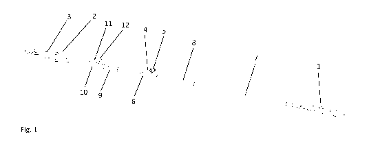
Fig. 1 shows a perspective view of an embodiment of a pulling tool according
to
the invention. The pulling tool comprises a main section 6 having a propulsion
wheel 5 mounted on a tilting arm 4 mounted between a first and a second
friction-
reducing roller wheel section 1, 2 with roller wheels 3. Roller wheels 3
extend
CA 03104068 2020-12-16
WO 2019/245381 PCT/N02019/050127
8
through and are supported by an elongate housing that is part of a tool
string.
Each roller wheel section 1, 2 is shown having four said wheels 3 supported so
as
to rotate about four rotation axes spaced 45 apart. Hence, each wheel has a
diameter that is larger than the diameter of the tool string. Said two roller
wheel
sections may be separated into a front roller wheel section 1 and a rear
roller
wheel section 2.
Typically, the different sections or parts may be constructed as separate
modules
that can be assembled and disassembled as required. Each section typically
comprises an elongate outer tubular housing having en external diameter that
is
smaller than the diameter of the pipe or bore in which the pulling tool is to
be used.
In a particular embodiment, the diameter of the tool is 42mm. Each section may
have suitable connectors at each end for connection to the adjacent section.
The
connectors must provide for both mechanical strength as well as any
transmissions of electrical power and signals.
Main section 6 having a tilting arm 4 with a propulsion wheel 5 comprises a
motor
and a gear system for driving the propulsion wheel. Typically, the motor is an
electric motor.
The tilting arm may be retracted so that the propulsion wheel is mainly
located
inside main section 6, and extended so that propulsion wheel 5 is pushed
against
the wall of a pipe or wellbore. The tilting arm typically functions in such a
manner
that springing is allowed and that the pressure against the wall of the pipe
or
wellbore is relatively constant independently of the deflection of the tilting
arm.
Tilting arm 4 is tiltable from main section 6.
The pulling tool further comprises a battery section 7, en electronic control
module
8, a pressure equalization module 9, and a counting wheel module 10.
Counting wheel module 10 comprise a tilting arm 11 with a rotating counting
wheel
12 that is pressed against the pipe or wellbore wall to provide information on
the
positioning of the tool in the well. Tilting arm 11 is spring-loaded and
flexible so
CA 03104068 2020-12-16
WO 2019/245381 PCT/N02019/050127
9
that it is automatically adjusted according to the size of the hole in which
the
pulling tool runs. Said rotating counting wheel 12 is provided with a counting
function that counts the number of revolutions, which is converted to a
distance
measurement by the electronic control module 8.
Electronic control module 8 may contain a Casing Collar Locator (CCL) for
depth
control, a pressure sensor, an accelerometer, a temperature sensor and a time
delay function. Electronic control module 8 may also include a controller for
the
motor of the main section.
Tilting arm 4 with propulsion wheel 5 can be actuated in several different
ways.
For example, by means of distance measurements from counting wheel module
10 and CCL, tilting arm 4 with propulsion wheel 5 can be actuated after a pre-
programmed distance. It is also possible to use a time delay function in that
the
pulling tool is actuated after a pre-programmed time. Another alternative is
to
actuate the pulling tool using the accelerometer. In this case, the cable can
be
pulled a given number of times pre-programmed for the pulling tool to be
actuated.
Thus, the pulling tool may run for a pre-programmed length that is measured by
means of counting wheel module 10 and CCL before propulsion wheel 5 is
stopped and tilting arm 4 is tilted in so that it is oriented with the same
axial
direction as main section 6.
Normally, the number of casing collars present in the well is known. The
pulling
tool, therefore, can detect the number of casing collars it passes through on
its
way into the well before the pulling tool is actuated. Thereafter the pulling
tool can
be actuated and run for a length and pass through a pre-programmed number of
casing collars before the pulling tool is stopped and de-actuated.
Fig. 2 shows a perspective view of an embodiment of the pulling tool according
to
the invention in which tilting arm 4 with propulsion wheel 5 has not been
actuated
and is extended in the same axial direction as main section 6.
CA 03104068 2020-12-16
WO 2019/245381 PCT/N02019/050127
Fig. 3 shows the pulling tool according to the invention inside a downhole
pipe 13
in a configuration for being run into the well before propulsion arm 4 is
actuated.
Fig. 4 shows the pulling tool inside a downhole pipe 13 in a configuration in
which
5 tilting arm 4 with propulsion wheel 5 has been actuated. Propulsion wheel
5 is
driven in rotation by an electric motor in the main section 6 which is
provided with
electrical power from battery section 7. When propulsion wheel 5 is driven and
abuts against the wellbore wall 14 with a tensioning force the pulling tool
will
advance the tool string inwardly in downhole pipe 13.
Fig. 5 shows further details of the pulling tool shown in Figs. 1-4. A tool
string 20 is
attached to an end of roller section housing 21 at which said four roller
wheels are
supported by four shafts 35 offset 45 relative to each other. A releasable
coupling
22 fastens roller section housing 21 with the counting wheel section to the
counting wheel section housing 23. A revolution sensor 37 of the counting
wheel
section counts the number of revolutions made by the counting wheel. An
elastic
unit 36 biases the counting wheel towards an outer position. A releasable
coupling
24 fastens counting wheel section housing 23 with the pressure equalization
module to pressure equalization module housing 25. A coupling 26 fastens
pressure equalization module housing 25 with the main section to a main
section
housing 40. A motor 38 for driving the propulsion wheel and an actuator 39 for
pressing the propulsion wheel against a wall are located in main section
housing
40. A coupling 27 fastens main section housing 40 with the control module to a
control module housing 28. Sensors 29 of control module housing 28 measures
desired parameters. Sensors 29 may include pressure sensor, temperature
sensor, gyroscope, inclinometer, accelerometer, various sensors such as fluid
parameters, flow sensors, acoustic sensors, etc. A releasable coupling 30
connects control module housing 28 to a battery section housing 31. A
releasable
coupling 32 connects the second roller wheel section with a roller wheel
section
housing 33 to battery section housing 31. An end piece 34 is connected to the
second end of roller wheel section housing 33. End piece 34 can be made for
receiving any impacts with the end of a wellbore or with other elements
against
which the unit may impact. End piece 34 may also contain sensors. The pulling
CA 03104068 2020-12-16
WO 2019/245381 PCT/N02019/050127
11
tool may also be constructed with more or fewer subdivisions, in which case
the
number of releasable couplings will vary. The housing may also be constructed
in
one piece. A first tension sensor 41 in the counting wheel section measures
the
tensile/compressive force in tool string 20 (on the rear roller wheel section)
and a
second tension sensor 42 of the battery section measures tensile/compressive
force on the front roller wheel section. Tensile/compressive force on the
front roller
wheel section may be used for measuring whether the pipeline pulling tool
impacts
with something or for measuring resistance against movement applied by a
string
or tool mounted to the pipeline pulling tool.
Alternatively, the second end of roller wheel section housing 33 may comprise
an
attachment for tools or a tool string, and one or more pulling tools according
to the
invention may be fastened to each other, with or without the presence of an
intermediate string or tool. In this case, the second end of roller wheel
section
housing 33 will not include end piece 34. Hence, the pulling tool can also be
used
for pushing equipment or a tool string in front thereof.
During operation in a pipe or bore, such as in an uncased hole, each roller
wheel 3
will abut against the wellbore wall. The diameter of roller wheels 3 is
smaller than
the diameter of the well, and normally all the wheels will not be in contact
with the
wellbore wall at the same time. As roller wheels 3 extend through the elongate
housing of roller wheel section 2, each roller wheel will support the pulling
tool on
two sides. Only one propulsion wheel 5 is needed because roller wheels 3 will
absorb the forces when propulsion wheel 3 is pressed against the wellbore wall
as
roller wheels 3 are also located both in front of and behind main section 6
with said
propulsion wheel 5 that is pressed against the wellbore wall through tilting
arm 4.
Operating only one main section 6 having one electric motor driving only one
propulsion wheel 5 yields good mechanical efficiency, which is particularly
important as the pulling tool is battery operated.
During operation the freely rotating counting wheel 12 of counting wheel
section
10 will also be pressed against the wellbore wall by the resilient tilting arm
11. Said
CA 03104068 2020-12-16
WO 2019/245381 PCT/N02019/050127
12
rotating counting wheel 12 is connected to a unit that records the rotation of
wheel
12 and transmits information to control module 8, which thereby obtains
information on the location of the pulling tool in the well. The resilient
tilting arm 12
does not need not include any actuator as the freely rotating wheel is to
record the
location of the tool along the entire length of the well.
If the operation of the propulsion wheel of the main section is not controlled
through a cable, the control module may selectively / automatically actuate
the
pulling tool based on time delay, velocity measured by the counting wheel
section,
tension in the tool string, parameters from the accelerometer, inclination,
etc. In
some cases it may be important that the propulsion wheel of the main section
is
put into operation before the pipeline pulling tool and tool string stop
because the
friction increases after stoppage and because start-up may then be
problematic.
The pressure sensor allows instructions to be sent to the electronic control
module
by way of liquid pulse telemetry in order to instruct start or stoppage of the
pulling
tool, for example.
Fig. 6 shows a perspective view of an alternative embodiment of a pulling tool
according to the invention. The embodiment is similar to the embodiments
described above, with some exceptions. The pulling tool includes a main
section 6
having a propulsion wheel 5 mounted on a tilting arm 4 mounted between a first
and a second friction-reducing roller wheel section 1, 2 with roller wheels 3.
Roller
wheels 3 extend through and are supported by the first and second roller wheel
sections 1, 2. Each roller wheel section 1, 2 is shown having two wheels 3
each
supported in a separate axle 3a so that each wheel rotates about its axis of
revolution. These axes of revolution / shaft 3a of each wheel are positioned
in
parallel to each other. The wheels of the first roller wheel section 1 are
situated in
the same plane as the wheels of the second roller wheel section 2. In other
words,
all the axes of revolution of the wheels are parallel with each other and
situated in
the same plane. Each wheel 3 has a diameter that is larger than a diameter of
the
tool string. As mentioned earlier, the roller wheel sections typically
comprise an
elongate outer tubular housing having an outer diameter that is smaller than
the
diameter of the pipe or bore in which the pulling tool is to be used.
CA 03104068 2020-12-16
WO 2019/245381 PCT/N02019/050127
13
The wheel axles extends outside the centre of the tubular housings of roller
wheel
sections 1, 2 so that each wheel protrudes further out on the one side of
roller
wheel sections than the other. The wheel axles are located outside the centre
of
the tubular housing, and are located on the opposite side of the centre of the
tubular housing relative to propulsion wheel 5.
The main section 6 having a tilting arm 4 with propulsion wheel 5 is as
described
in connection with the other embodiments, but propulsion wheel 5 has an axis
of
revolution that is parallel with the rotation axes of the freely supported
roller
wheels 3. Roller wheels 3 and propulsion wheel 5 are situated in the same
plane,
but are positioned on different sides of the respective tubular housings so
that a
force applied by propulsion wheel 5 to the wellbore or pipe wall is absorbed
and
distributed between the four roller wheels 3. Thus, this force is
perpendicular to all
wheel axles, both of the four roller wheels 3 and of propulsion wheel 5.
Further, the second roller wheel section 2 is adjacent to main section 6 with
propulsion wheel 5 so that the distance between roller wheels 3 of at least
the
second roller wheel section 2 and propulsion wheel 5 of the main section 6 is
short. This means that the moment applied to the tool housing exerted by
propulsion wheel 5 on tilting arm 4 is small so that the deflection of the
tubular
housing due to propulsion wheel 5 is small.
The pulling tool further comprises the battery section 7, electronic control
module
8, and pressure equalization module 9. A brain or electronics unit 8b
records,
stores, and/or processes various data.
As all roller wheels 3 are in line and propulsion wheel 5 is situated in the
same
plane as roller wheels 3, the pulling tool will seek towards the centre of the
pipe/bore in which the tool is deployed as the tool will be located where the
pipe/bore diameter is greatest.
CA 03104068 2020-12-16
WO 2019/245381 PCT/N02019/050127
14
The short distance between roller wheels 3 and the propulsion wheel results in
only a small deflection of the tubular housing. This prevents the tubular
housing
from bending and reduces the risk that the tubular housing sweeps internally
in the
wall of the pipe/bore causing increased resistance and wear. The roller wheels
3
of each section are positioned one behind the other at a close distance,
although
not so close that the roller wheels 3 contact each other.
In Fig. 6 the first roller wheel section 1 is attached to pressure
equalization module
9, which is in turn attached to main section 6 which is in turn attached to
the
second roller wheel module 2.
In the solution of Fig. 6 all wheels will be positioned so as to absorb the
force from
the pressing by the propulsion wheel against the wall and to distribute the
forces to
all four wheels. This allows the number of roller wheels 3 to be reduced
without
increasing the pressure from the wheels against the surface.
In the patent claims, it is claimed that the pulling tool comprises an
attachment for
a tool string 20. In this relation the term tool string is intended to
include cables,
pipes, downhole packers, perforating guns, logging tools, bridge plugs, fibre
optic
cable, slick line, signal cable as well as other equipment being used in a
pipe or
well. Hence, the claim is not intended to be limited based on what is to be
pulled or
pushed by the pulling tool. Similarly, the end piece 34 can be replaced by a
tool
string as defined above.
Also, in the patent claims the term pipeline pulling tool is intended to
include a
tool that may also be used in uncased bores in wells or other bores, and the
invention is hence not limited to a pulling tool intended exclusively for
pipelines.
In the description set out above a particular order of parts and sections is
indicated. It is important that the main section is located between the roller
wheel
sections. However, the ordering of the remaining sections can be changed
without
departing from the invention. When it is described that the main section is
located
between the roller wheel sections, this is not intended to exclude the
possibility
CA 03104068 2020-12-16
WO 2019/245381 PCT/N02019/050127
that further sections are located between the roller wheel sections as well
but is
only intended to describe that a roller wheel section is present ahead of the
main
section and a roller wheel section is present behind the main section.
However, it
is important that a certain rigidity is ensured between the roller wheel
sections.
5
The distance between the roller wheel sections and the rigidity of the pulling
tool
are chosen so that the tilting arm with a propulsion wheel does not bend the
pulling tool causing the pulling tool to contact the wall of the pipeline or
bore in
which the pulling tool is deployed. In other words, the pulling tool possesses
a
10 rigidity between the roller wheel sections that prevents the main
section from
pressing other parts than the roller wheels against the pipeline or bore.