Note : Les descriptions sont présentées dans la langue officielle dans laquelle elles ont été soumises.
VEHICLE PARTITION FOR SINGLE PASSENGER AND SECURE STORAGE AREA
BACKGROUND
[001] Partitions for passenger vehicles typically are used to separate the
interior space of a
vehicle into separated areas for different uses. According to one common type
of partition used
in law enforcement vehicles, the rear occupant area (typically suited for two
passengers) is
separated from the front occupant area (typically suited for a driver and a
passenger) by a
partition. This type of partition separates one or two law enforcement
officers seated in the front
seat area from one, two or sometimes three rear seat occupants, such as
suspects, prisoners, and
other individuals, thereby reducing the risks of injury to the law enforcement
officers from the
rear seat occupants, as well as restricting the ability of the rear seat
occupants to escape from the
vehicle.
[002] Additionally, law enforcement officers often have a variety of equipment
and other gear,
which must be typically be stored in a secure location within the vehicle such
that it cannot be
accessed by non-law enforcement officers. In some vehicles, it may be
desirable to store such
gear in the cab portion of the vehicle, such as in the rear occupant area.
However, such gear
must also be secured such that it cannot be accessed by a rear seat passenger.
Accordingly, a
need exists for improved vehicle partitions that provide for one or more
secure storage areas.
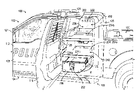
SUMMARY
[003] Described herein are embodiments of a vehicle partition for single
passenger and secure
storage areas. The described partitions can be used to separate a rear seat
occupant (e.g., a
passenger, suspect, and/or prisoner) from a storage area located adjacent the
rear seat occupant.
[004] In a representative embodiment, a partition assembly can comprise a
partition member, a
platform member, and a drawer. The partition member can extend along a first
axis and have a
first side surface and a second side surface. The partition member can define
a storage area and
a prisoner area. The platform member can be coupled to the first side surface
of the partition
member and can extend from the partition member along a second axis
perpendicular to the first
axis. The drawer can be coupled to the platform member and can be slidable
between an open
position and a closed position along the second axis.
- 1 -
Date Recue/Date Received 2021-01-06
[005] In some embodiments, the platform member can be a first platform member
and the
assembly can further comprise a second platform member coupled to and
extending from the
first side surface of partition member along the second axis. The second
platform member can be
spaced apart from the first platform member along the first axis to define an
obscured storage
area between them.
[006] In some embodiments, the partition assembly can be disposed in a rear
occupant area of
the vehicle.
[007] In some embodiments, the partition assembly can further comprise a
communications
housing coupled to the platform member and defining an inner storage area. In
such
embodiments, a movable panel can be pivotably coupled to the communications
housing, the
movable panel being movable between an open position and a closed position,
wherein when the
movable panel is in the open position the inner storage area can be accessed.
In some
embodiments, the movable panel comprises one or more latches configured to
selectively retain
the movable panel in the closed position.
[008] In some embodiments, the drawer further comprises a locking mechanism
configured to
selectively retain the drawer in the closed position.
[009] In some embodiments, the partition assembly further comprises one or
more flanges
configured to allow the partition assembly to be coupled to the vehicle via
one or more fasteners.
[010] In some embodiments, the partition member can comprise one or more vents
extending
through a thickness of the partition member. In such embodiments, the
partition assembly can
comprise one or more vent covers configured to prevent a passenger seated in
the prisoner area
from accessing the storage area while allowing air to flow through the one or
more vents
between the storage area and the prisoner area.
[011] In some embodiments, the platform member can comprise one or more
cutouts
configured to allow the platform member to conform to contours of one or more
interior features
of the vehicle.
[012] In some embodiments, the partition member can comprise polycarbonate. In
some
embodiments, the partition assembly can further comprise a seat portion
coupled to the second
side surface of the partition member.
- 2 -
Date Recue/Date Received 2021-01-06
[013] In some embodiments, the drawer can comprise a housing defining a lumen
and a
slidable member configured to extend at least partially into the lumen. In
such embodiments, the
housing can comprise a first set of rails and wherein the slidable member
comprises a
corresponding second set of rails configured to engage the first set of rails.
[014] In another representative embodiment, a partition assembly for use in a
vehicle having a
front occupant area and a rear occupant area and comprising a first rear area
door on a driver-
side of the vehicle and a second rear area door on a passenger-side of the
vehicle, the first and
second rear area doors being movable between a closed position and an open
position, can
comprise a partition member, a platform member, and a drawer. The partition
member can be
configured to extend between a driver-side portion and a passenger-side
portion of the rear
occupant area and between a floor and a ceiling of the vehicle in a vertical
direction. The
platform member can be coupled to the partition member and configured to
extend horizontally
between the partition member and a first side of the vehicle comprising the
first rear door. The
drawer can be coupled to the platform member and can be movable between a
closed position
and an open position. The drawer can be configured such that when the drawer
and the first rear
door are in the open position the drawer does not contact the first rear door.
[015] In some embodiments, the platform member can be a first platform member
and the
partition assembly can further comprise a second platform member coupled to
the partition
member and spaced apart from the first platform member in the vertical
direction. The second
platform member can be configured to extend horizontally between the partition
member and the
first side of the vehicle. In such embodiments, the first and second platform
members can define
a first storage area between them and a second storage area between the second
platform member
and the ceiling of the vehicle. The first storage area can be positioned such
that a person looking
in through a window of the vehicle cannot see into the first storage area.
[016] In some embodiments, the partition assembly can further comprise a
communications
housing coupled to the platform member and extending toward the ceiling of the
vehicle, the
communications housing defining an inner storage area. In such embodiments,
the
communications housing can further comprise a movable panel configured to move
between an
open position and a closed position. When the movable panel is in the open
position the inner
storage area can be accessible from an interior of the vehicle.
- 3 -
Date Recue/Date Received 2021-01-06
[017] The foregoing and other features, and advantages of the disclosure will
become more
apparent from the following detailed description, which proceeds with
reference to the
accompanying figures.
BRIEF DESCRIPTION OF THE DRAWINGS
[018] FIG. 1 is a perspective view of an exemplary embodiment of a partition
assembly
installed in an exemplary vehicle.
[019] FIG. 2 is a perspective view of the partition assembly of FIG. 1 with
the upper platform
member removed.
[020] FIG. 3 is a front view of the partition assembly of FIG. 1 with the
upper platform member
removed.
[021] FIG. 4 is a rear view of the partition assembly of FIG. 1 with the upper
platform member
removed.
[022] FIG. 5 is a left-side elevational view of the partition assembly of FIG.
1 with the upper
platform member removed.
[023] FIG. 6 is a right-side elevational view of the partition assembly of
FIG. 1 with the upper
platform member removed.
[024] FIG. 7 is a top plan view of the partition assembly of FIG. 1 with the
upper platform
member removed.
[025] FIG. 8 is a bottom plan view of the partition assembly of FIG. 1.
[026] FIG. 9 is a perspective view of the partition assembly of FIG. 1 with
the upper platform
member removed.
[027] FIG. 10 is a perspective view of the partition assembly of FIG. 1 with
the upper platform
member removed and positioned adjacent to an exemplary rear occupant seat.
[028] FIG. 11 is a perspective view of the partition assembly of FIG. 1
installed in a vehicle
with portions of the vehicle removed for purposes of illustration.
[029] FIG. 12 is a perspective view of the partition assembly of FIG. 1
installed in a vehicle
with portions of the vehicle removed for purposes of illustration.
- 4 -
Date Recue/Date Received 2021-01-06
DETAILED DESCRIPTION
[030] Described herein are embodiments of a partition assembly for use in a
vehicle. Though
some of the below embodiments are described with respect to vehicles having a
particular
combination of features (for example, a front occupant area, a rear occupant
area, and a cargo
area such as a flatbed) , it should be understood that the described partition
assemblies can be
used with any type of vehicle.
[031] The described partition assemblies can be used in combination with one
or more
additional partitions, such as partitions that separate the front occupant
area from the rear
occupant area. Additional details of such partitions can be found, for
example, in U.S. Patent
No. 8,708,388, which is incorporated by reference herein in its entirety.
[032] FIG. 1 illustrates an exemplary vehicle 100 in which a partition
assembly such as
partition assembly 200 (see FIGS. 2-10) can be installed. The vehicle 100 can
include a
passenger compaiiment or cab 102 having a front occupant area 104 and a rear
occupant area
106. The vehicle 100 can include a first side portion 108 (also referred to as
the driver-side
portion), and a second portion 110 (see FIG. 12, also referred to as the
passenger-side portion).
The front occupant area 104 can have a first door 112 and a second or
passenger-side door 114
(see FIG. 12). The front occupant area 104 can comprise a driver seat 113 and
a passenger seat
115 (see FIG. 12). The rear occupant area can have a first door 116 and a
second door 118 (see
FIG. 12). The rear occupant area 106 can comprise one or more passenger seats
(see e.g.,
passenger seat 274 in FIG. 10). The vehicle 100 can further include a floor
122 (FIG. 12) and a
ceiling or roof 124 supported by a plurality of pillars such as one or more A-
pillars 125, a first B-
pillar 126 and a second B-pillar (not shown) disposed adjacent the driver-side
portion and the
passenger-side portion, respectively, and one or more C-pillars 127.
[033] In some embodiments, such as the illustrated embodiment, the vehicle 100
can include an
external cargo area 130 such as a pickup truck bed as shown or a flat-bed. In
other
embodiments, the vehicle 100 can have an interior cargo area such as a trunk.
[034] In some particular embodiments, the first and second doors 116, 118 of
the rear occupant
area 106 can be configured to open such that the door extends at approximately
a 90 degree
angle from the body of the vehicle 100 (e.g., such that the door extends
perpendicularly to a
longitudinal axis extending along the length of the vehicle). Such embodiments
may facilitate
- 5 -
Date Recue/Date Received 2021-01-06
opening and closing of one or more storage portions of the partition assembly
200, as described
in more detail below.
[035] The partition assembly 200 can be disposed within the cab 102 of the
vehicle 100 and
generally comprises a partition member, one or more platform members, and one
or more storage
portions or drawers. FIGS. 1-12 illustrate an exemplary embodiment of a
partition assembly 200
including a partition member 202, a first, or lower platform member 204a and a
second, or upper
platform member 204b (FIG. 1), and one or more drawers 206. The partition
member 202 can be
configured to define a storage area 201 on one side of the vehicle and a
prisoner area 203 on the
opposite side (see FIG. 10). In the illustrated embodiment, the storage area
201 is disposed on
the driver-side of the vehicle 100 and the prisoner area 203 is on the
passenger-side of the
vehicle, however, in other embodiments, the storage area may be disposed on
the passenger-side
of the vehicle and the prisoner area 203 may be disposed on the driver side of
the vehicle.
[036] As mentioned, the partition assembly 200 can comprise first and second
platform
members 204a and 204b, although FIGS. 2-10 omit the second platform member
204b for
purposes of illustration. FIGS. 1, 11, and 12 illustrate an embodiment wherein
one or more
portions of the partition member 202 are transparent and/or translucent and
wherein the vent 220
does not comprise a vent cover 224. The other aspects of the partition
assembly remain the
same.
[037] Referring to FIG. 2, the partition member 202 can have a height
extending along a first
axis (e.g., a Z-axis as shown in coordinate system 208) from an inner surface
of the floor 122
(FIG. 1) to an inner surface of the roof 124 (FIG. 1), and a width extending
along a second axis
(e.g., an X-axis), perpendicular to the first axis. In other words, the
partition member 202 can
extend vertically between the floor 122 and ceiling 124 of the vehicle in the
orientation shown in
FIG. 2. The partition member 202 can have a first surface 210 facing the first
side 108 (e.g., the
driver side) of the vehicle and a second surface 212 (FIG. 3) facing the
second side 110 of the
vehicle (e.g., the passenger side). The first and second surfaces 210, 212 can
be connected by a
plurality of edges 214. For example, the partition member 202 can have a top
edge 214a, a first
side edge 214b, a second side edge 214c, and a bottom edge 214d.
[038] The edge portions 214 can comprise a variety of cutouts 216 and angled
portions 218
configured to allow the partition member 202 to be disposed within the pre-
existing shape of the
vehicle cab. For example, in the illustrated embodiment, as shown in FIG. 2,
the top edge 214a
- 6 -
Date Recue/Date Received 2021-01-06
can comprise a first cutout 216a at a rear portion thereof, the first side
edge 214b can comprise a
first angled portion 218a and a second angled portion 218b, the second side
edge 214c can
comprise a second cutout 216b and a third cutout 216c, and the bottom edge
214d can comprise a
fourth cutout 216d and a fifth cutout 216e. Side edge 214b can further
comprise an additional
semi-circular cutout 216f. However, in other embodiments, the partition member
202 can have
any of various cutouts on any of various edges in order to conform to the
shape of the vehicle in
which it is disposed.
[039] Optionally, the partition member 202 can further comprise one or more
vents comprising
a plurality of apertures. The apertures can extend through a thickness of the
partition member
202. In other words, the vents can establish airflow communication between the
storage area
201 and the prisoner area 203. In the illustrated embodiment, the partition
member 202
comprises a first vent 220 and a second vent 222 (see FIG. 6). One or more of
the vents 220, 222
can comprise a vent cover such as vent cover 224. The vent cover 224 can be
configured to
prevent a passenger from reaching through the vent 220, 222 into the storage
area 201 while still
allowing the flow of air through the partition member 202, and can further
prevent prisoners
from hiding and/or transferring contraband. The vent cover 224 can be coupled
to the partition
member 202 using one or more fasteners 226. The fasteners 226 can be any of
various fasteners
including but not limited to conventional threaded fasteners, such as screws
and/or bolts. As
shown in FIG. 7, the vent cover 224 can be coupled to the partition member 202
using one or
more struts 227. The struts 227 can space the vent cover 224 away from the
partition member
202, facilitating the flow of air through the vent.
[040] In some embodiments, the partition member 202 can comprise one or more
partially
transparent or translucent portions (see e.g., FIGS. 1 and 11-12). For
example, the partition
member 202 can comprise a polycarbonate, such as a coated, scratch resistant
polycarbonate. In
some embodiments, some or all of the partition member can comprise steel. In
some
embodiments, the partition member can additionally comprise a covering (e.g.,
bars, a screen,
mesh, or other covering) comprising vinyl coated expanded metal and/or coated
polycarbonate.
In still other embodiments, the partition member 202 can be formed from and/or
include any of
various known barrier materials, such as wire mesh and/or sheet metal.
[041] As mentioned previously, the partition assembly 200 can include one or
more platform
members 204. Referring again to FIG. 1, the illustrated embodiment comprises a
first, or lower
- 7 -
Date Recue/Date Received 2021-01-06
platform member 204a, and a second, or upper platform member 204b. Each
platform member
204 can extend laterally from the first surface 210 of the partition member
202 along a third axis
perpendicular to the first and second axes (e.g., a Y-axis as shown by
coordinate system 208)
toward the first door 116 (e.g., the passenger-side door) of the rear occupant
area 106. Each
platform member 204 can have a first, upper surface 228 and a second, lower
surface 230 (see
FIG. 3).
[042] As shown in FIG. 2, each platform member 204 can have a substantially
rectangular
shape comprising one or more cutouts 232. The cutouts 232 can be configured to
allow each
platform member 204 to conform to the interior shape of the vehicle 100. For
example, as seen
in FIG. 7, platform member 204a can have a first cutout 232a can be configured
to allow the first
door 116 of the rear occupant area 106 to open and close, and a second cutout
232b configured to
accommodate additional features of the vehicle 100. Platform member 204a can
further
comprise a third cutout 232c configured to allow the partition assembly 200 to
be used together
with one or more additional partitions, such as partitions that separate the
front occupant area
104 from the rear occupant area 106. Additional details of such partitions can
be found, for
example, in U.S. Patent No. 8,708,388.
[043] Referring again to FIG. 2, each platform member 204 can have one or more
flanges 234.
The flanges 234 can extend from the first surface 228 in a substantially
vertical direction. In
some embodiments, the flanges 234 can be angled. For example, in the
illustrated embodiment,
platform member 204a has four flanges 234 configured as a front flange 234a,
first side flange
234b, second side flange 234c, and rear flange 234d, respectively. Flange 234a
is angled into the
rear occupant area 106. The angled shape of flange 234a can help couple the
platform member
204a to a rear portion of the driver's seat and/or an angled portion of a
partition assembly
extending between the front occupant area and the rear occupant area. Each
flange 234 can
extend all or part of the way along a width or a depth of the platform member
204. For example,
in the illustrated embodiment, the flanges 234 do not extend into the areas
defined by the cutouts
232.
[044] Some flanges 234 can comprise one or more apertures 236 configured to
receive a
fastener (e.g., a threaded fastener such as a screw or bolt) such that the
platform member 204a
can be coupled to other components of the partition assembly 200 (e.g., the
partition member 202
and/or the drawer 206), to the vehicle 100, and/or to additional partition
assemblies disposed
- 8 -
Date Recue/Date Received 2021-01-06
within the vehicle. For example, in the illustrated embodiment flange 234a has
three apertures
236. Some flanges 234, for example second side flange 234c can further prevent
items placed in
the storage area 201 from sliding off the platform member during movement of
the vehicle 100
or opening of the vehicle doors.
[045] In the illustrated embodiment, the first side flange 234b can be coupled
to the partition
member 202, the second side flange 234c can be coupled to the drawer 206, and
the front flange
234a can be coupled to a rear portion of the driver's seat and/or to an
additional partition
assembly disposed between the front occupant area 104 and the rear occupant
area 106.
[046] As mentioned previously, in some embodiments, as shown in FIGS. 1 and 11-
12, the
partition assembly 200 can include a second platform member 204b, which is
substantially
similar to the first platform member 204a. As shown in FIG. 1, the platform
members 204a,
204b can be spaced apart from one another vertically along the first or Z-
axis. The placement of
the platform members 204a, 204b can define a visible storage area 238 and an
obscured storage
area 240 within the storage area 201. The obscured storage area 240 can be
configured to be
shielded from view when the vehicle doors (e.g., the rear occupant doors such
as door 116) are
closed such that a person passing by the vehicle 100 and/or looking in through
the vehicle
windows cannot see what materials are located within the obscured storage area
240. In some
embodiments, the partition member 202 can comprise an opaque or darkened
portion
corresponding to the location of the obscured storage area 240 such that a
passenger sitting in the
prisoner area 203 cannot see into the obscured storage area 240 through the
partition member
202.
[047] As mentioned previously, the partition assembly 200 can comprise one or
more drawers
206. Each drawer 206 can be coupled to a lower surface (e.g., lower surface
230) of a platform
member 204. For example, in the illustrated embodiment, the partition assembly
200 has one
drawer 206 coupled to the lower surface 230 of the first platform member 204a.
In other
embodiments, the partition assembly can comprise various drawers. For example,
in some
embodiments, the obscured storage area 240 can comprise one or more additional
drawers 206
disposed between the first platform member 204a and the second platform member
204b.
[048] Referring to FIG. 11, each drawer 206 can comprise a housing 242 and a
slidable
member 244. The housing 242 can define a lumen 246 into which the slidable
member 244 can
extend. The slidable member 244 can slide relative to the housing 242 between
a closed position
- 9 -
Date Recue/Date Received 2021-01-06
(FIGS. 2-10) and an open position in the direction of the third or Y-axis, as
shown by coordinate
system 208 (see FIG. 11). The housing 242 can comprise rails 248 configured to
engage
corresponding rails 250 of the slidable member to facilitate movement of the
slidable member
244 relative to the housing 242.
[049] As mentioned previously, in some embodiments, the first 116 and second
rear occupant
doors can be opened such that they define a 90 degree or approximately 90
degree angle with the
body of the vehicle, or an even greater angle, in some cases. In such
embodiments, as shown in
FIG. 1, the drawer 206 can be configured to extend into the open position
without contacting the
rear occupant door 116. For example, the drawer 206 can have a shape
configured to allow the
drawer 206 to be opened without interfering with the frame of the vehicle 100
or with the vehicle
door 116, such as a cross-sectional shape that is substantially rectangular
with one corner (e.g.,
corner 205 as shown in FIG. 2) removed/cut off.
[050] Each drawer 206 can be configured to store any variety of materials
and/or gear. For
example, the drawer 206 can be used to store materials used during law
enforcement activities,
such as firearms, restraints, illuminating devices (e.g., flashlights and/or
flares), communication
equipment, and/or any other necessary materials.
[051] Each drawer can further comprise a handle or gripping portion 252
configured to
facilitate opening of the drawer 206. In some embodiments, such as the
illustrated embodiment,
the gripping portion 252 can further comprise a locking mechanism 254. The
locking
mechanism 254 can be configured to retain the drawer in the closed position.
In other
embodiments, the drawer need not include a locking mechanism.
[052] In some embodiments, the locking mechanism 254 can comprise a rotatable
member (not
shown) coupled to the slidable member 244 and a locking flange 256 (see FIG.
11) coupled to
the housing 242 and extending into the lumen 246. When the drawer 206 is in
the closed
position, a user can rotate the rotatable member such that an end portion of
the rotatable member
engages the locking flange 256, thus preventing the slidable member 244 from
sliding relative to
the housing 242. In other embodiments, the flange 256 may be mounted on the
platform member
204.
[053] In some embodiments, the drawer 206 can further comprise a second
gripping portion
257. The second gripping portion 257 can be, for example, a curved member
extending from an
- 10 -
Date Recue/Date Received 2021-01-06
upper portion of the drawer 206, as best shown in FIG. 4. A user can grip the
second gripping
portion 257 to actuate the slidable member 244 between the open and closed
positions.
[054] Referring again to FIG. 2, the partition assembly can further comprise a
communications
housing 258. In some embodiments, the communications housing 258 can be
configured to
house one or more communications arrays, including, for example, radio
receivers and
transmitters, etc. In other embodiments, the communications housing 258 can
serve as an
additional storage area to house any of various materials.
[055] The communications housing 258 can comprise a first or front panel 258a
(FIG. 3), a
second or top panel 258b (FIG. 7), a third or rear panel 258c (FIG. 4), and a
fourth or bottom
panel 258d (FIG. 9). As seen in FIG. 5, the panels 258a-258d can define a
communications
storage area 260 between them. In some embodiments, the housing 258 need not
comprise a
bottom panel 258d, but rather can be mounted directly to a platform member 204
such that the
upper surface 228 of the platform member 204 serves as the bottom panel.
[056] Referring to FIG. 3, the front panel 258a can comprise a movable panel
262 coupled to
the front panel 258a by one or more hinges 264. The movable panel 262 can
pivot about the
hinges 264 between a closed position (see FIG. 2) and an open position (not
shown). When the
movable panel 262 is in the open position a user can access materials located
within the
communications storage area 260 from the storage area 201. When the movable
panel 262 is in
the closed position it can prevent or mitigate access to the communications
storage area 260.
[057] The movable panel 262 can further comprise one or more locking
mechanisms or latches
266 movable between a locked position and an unlocked position. In the
illustrated embodiment,
the movable panel 262 includes two laches 266. When in the locked position,
the one or more
latches can be configured to engage the front panel 258a to retain the movable
panel 262 in the
closed position. When in the unlocked position, the one or more latches 266
can be disengaged
from the front panel 258a to allow movement of the movable panel 262.
[058] In some embodiments, each latch 266 can comprise, for example, an
actuating member
268 (see FIG. 3) coupled to an engagement member 270 (see FIG. 5). When the
latch 266 is in
the locked position, as shown in FIG. 5, the engagement member 270 can be
positioned such that
it engages the front panel 258a, preventing or mitigating movement of the
movable panel 262
into the open position.
- 11 -
Date Recue/Date Received 2021-01-06
[059] Referring again to FIG. 2, the partition assembly 200 can be coupled to
the vehicle using
one or more brackets 272. Each bracket 272 can comprise one or more apertures
configured to
receive a respective fastener, for example, a conventional fastener such as a
screw or bolt. The
partition assembly 200 can comprise any number of brackets, the brackets can
have any shape as
needed to fit against the vehicle, and the brackets can be disposed at any
location on the partition
assembly, as needed, to securely couple the assembly to the vehicle.
[060] In the illustrated embodiment, some brackets, such as brackets 272a,
272b can be
conventional L-shaped brackets. Brackets, such as conventional L-shaped
brackets, can further
be used in combination with one or more additional brackets. For example, in
the illustrated
embodiment as shown in FIG. 3, an L-shaped bracket 272c can be coupled (e.g.,
via a fastener
such as a screw or bolt) to bracket 272d. This combination of brackets can be
configured to
couple the partition assembly 200 to the floor and/or side wall of the vehicle
100.
[061] As shown in the illustrated embodiment, the partition assembly can
further comprise
brackets 272e and 272f, which can be configured to couple the partition
assembly to the roof 124
and/or portions of the factory-installed seat assembly, respectively. The
partition assembly 200
can further comprise an elongated U-shaped bracket 272g coupled to the second
surface 230 of
the platform member 204a and configured to couple the partition assembly 200
to portions of the
factory-installed seat assembly.
[062] The brackets 272 can be formed of any suitable material for carrying the
loads transferred
from the partition, such as, e.g., 3/16" to 1/4" steel plate. Although the
brackets 272 are shown as
single pieces, any may be formed in multiple pieces depending upon the
specific requirements.
The various components of the partition assembly 200 may be assembled
together, coupled to
the vehicle 100, and/or coupled to an additional partition assembly using
conventional threaded
fasteners, such as screws or bolts.
[063] FIGS. 11-12 illustrate an exemplary partition assembly 200 installed in
a vehicle 100. As
mentioned previously, the partition assembly 200 illustrated in FIGS. 11-12
has a transparent or
translucent partition member 202, and includes a second, upper platform member
204b. All
other features are as described previously. FIGS. 11-12 omit the rear occupant
area doors for
purposes of illustration.
- 12 -
Date Recue/Date Received 2021-01-06
[064] In some embodiments, in order to install the partition assembly 200, the
factory-installed
rear occupant seats must be removed from the vehicle 100. In such embodiments,
the partition
assembly can include a seat, such as seat 274 shown in FIG. 10. In other
embodiments, only
portions of the factory-installed occupant seats must be removed to install
the partition assembly
200. For example, in some embodiments, the factory-installed rear occupant
seat(s) on the
driver-side of the vehicle can be removed to accommodate the storage area 201,
and the factory-
installed rear occupant seat(s) on the passenger-side of the vehicle can
remain in the vehicle for
use in the prisoner area 203.
[065] Referring to FIG. 12, in some embodiments, the partition assembly 200
can be used in
combination with a seatbelt docking device 300. The seatbelt docking device
300 can comprise
a docking member 302 coupled to a portion of the vehicle. For example, in the
illustrated
embodiment, the seatbelt docking device 300 is coupled to an additional
partition assembly such
as the partition assembly shown in U.S. Patent No. 8,708,388, via a support
member 304. In
other embodiments, the seatbelt docking device 300 can be coupled to the
partition assembly
200, or to a portion of the vehicle frame such as a B pillar 126.
[066] The seatbelt docking device 300 can be used in the following exemplary
manner. Prior to
the placement of a prisoner in the prisoner area 203, a user (e.g., a law
enforcement officer) can
"dock" a seatbelt, such as seatbelt 306 having a tongue portion 308 and a belt
portion 310, by
inserting the tongue portion 308 into the docking member 302. Once the
prisoner has been
placed in the prisoner area 203, the user can release the tongue portion 308
of the seatbelt, for
example, by clicking a button or other release member on the docking member
302. The user
can then insert the tongue portion 308 into the factory docking member 312,
securing the
prisoner's seatbelt in place. Use of the docking member 302 can prevent or
mitigate the need for
the user to reach across the prisoner in order to reach the seatbelt, thereby
preventing or
mitigating the risk of harm to the user by the prisoner.
General Considerations
[067] For purposes of this description, certain aspects, advantages, and novel
features of the
embodiments of this disclosure are described herein. The disclosed methods,
apparatus, and
systems should not be construed as being limiting in any way. Instead, the
present disclosure is
directed toward all novel and nonobvious features and aspects of the various
disclosed
embodiments, alone and in various combinations and sub-combinations with one
another. The
- 13 -
Date Recue/Date Received 2021-01-06
methods, apparatus, and systems are not limited to any specific aspect or
feature or combination
thereof, nor do the disclosed embodiments require that any one or more
specific advantages be
present or problems be solved.
[068] Although the operations of some of the disclosed embodiments are
described in a
particular, sequential order for convenient presentation, it should be
understood that this manner
of description encompasses rearrangement, unless a particular ordering is
required by specific
language set forth below. For example, operations described sequentially may
in some cases be
rearranged or performed concurrently. Moreover, for the sake of simplicity,
the attached figures
may not show the various ways in which the disclosed methods can be used in
conjunction with
other methods. Additionally, the description sometimes uses terms like
"provide" or "achieve"
to describe the disclosed methods. These terms are high-level abstractions of
the actual
operations that are performed. The actual operations that correspond to these
terms may vary
depending on the particular implementation and are readily discernible by one
of ordinary skill in
the art.
[069] All features described herein are independent of one another and, except
where
structurally impossible, can be used in combination with any other feature
described herein.
[070] As used in this application and in the claims, the singular forms "a,"
"an," and "the"
include the plural forms unless the context clearly dictates otherwise.
Additionally, the term
"includes" means "comprises." Further, the terms "coupled" and "associated"
generally mean
electrically, electromagnetically, and/or physically (e.g., mechanically or
chemically) coupled or
linked and does not exclude the presence of intermediate elements between the
coupled or
associated items absent specific contrary language.
[071] In the following description, certain terms may be used such as "up,"
"down," "upper,"
"lower," "horizontal," "vertical," "left," "right," and the like. These terms
are used, where
applicable, to provide some clarity of description when dealing with relative
relationships. But,
these terms are not intended to imply absolute relationships, positions,
and/or orientations. For
example, with respect to an object, an "upper" surface can become a "lower"
surface simply by
turning the object over. Nevertheless, it is still the same object.
[072] In view of the many possible embodiments to which the principles of the
disclosure may
be applied, it should be recognized that the illustrated embodiments are only
preferred examples
- 14 -
Date Recue/Date Received 2021-01-06
and should not be taken as limiting the scope of the disclosure. Rather, the
scope of the
disclosure is defined by the following claims. We therefore claim all that
comes within the
scope and spirit of these claims.
- 15 -
Date Recue/Date Received 2021-01-06