Note : Les descriptions sont présentées dans la langue officielle dans laquelle elles ont été soumises.
CA 03105399 2020-12-30
WO 2020/007465
PCT/EP2018/068148
1
Flap closure
Description
The present invention relates to a flap closure comprising a closure body and
a flap cover
connected to one another by at least one hinge and at least one tensioning
band in order
to achieve a snap-effect when opening and/or closing the flap cover.
The snap closure is preferably made of plastic, particularly by injection
molding. In this
case, the closure body and the flap cover inclusive of the at least one hinge
and the at
least one tensioning strap can be injection molded together; i.e. in one
piece. It is however
also possible to first injection mold one component, in particular the closure
body, and then
inject the other components onto it, in particular the flap cover with the at
least one hinge
and the at least one tensioning strap. Conversely, the flap cover can also be
injection
zo molded first and the closure body then molded onto it. In both cases,
the at least one hinge
and the at least one tensioning band can be injection molded together with the
closure
body or together with the flap cover.
The injection position of the flap closure; i.e. the position in which the
closure body and the
flap cover are injected together or injected onto one another respectively, is
preferably a
position of the flap cover open approximately 180 degrees. Since the flap
closure is
originally cast in this position, no mechanical forces act on its individual
components in this
position. In particular, the at least one tensioning band is thus unloaded in
the injection
position; i.e. not subject to any tensile or bending stresses or other
mechanical forces.
Date Recue/Date Received 2020-12-30
CA 03105399 2020-12-30
WO 2020/007465
PCT/EP2018/068148
2
The at least one hinge is preferably designed as a living hinge; i.e. a thin
segment in the
material along a line which corresponds to the hinge's axis of rotation. The
hinge function
thereby results from the material's increased flexibility at this thin
segment.
By the flap cover pivoting about the axis of the at least one hinge, the flap
cover can be
brought into at least one, in particular fully closed position and into at
least one open
position.
The closure body preferably comprises an opening for dispensing a product
which is
covered, preferably tightly sealed, by the flap cover in its closed position.
The closure body is designed to be attached to a container, in particular to a
bottle,
particularly by being screwed or snapped on. Flap closures of the type
considered are
used to dispense a multitude of liquid, pasty, powdery, granular, lumpy or
otherwise
flowable or pourable products from the container, e.g. for personal care or
other care
products, cosmetics, oils or fats, cleaning agents, medicines, foodstuffs or
beverages.
When the closure body is attached to the container, the flap cover can
preferably be
opened with a single finger, preferably the thumb, and snaps into a stable
open position
zo upon overcoming a specific opening angle, the "snap-over angle." In this
open position,
the flap cover is then not in the way when the product is being dispensed from
the
container. Particularly when the container is used as a drinking bottle, the
flap cover does
not impede the user's drinking by coming into contact with the user's mouth or
nose.
Conversely, the flap cover can be closed from its open position, preferably
again with just
a single finger, and preferably snaps back again into the fully closed or a
nearly closed
position upon overcoming a specific opening angle, again in particular the
snap-over angle,
whereby it can preferably be brought from the nearly closed position into the
fully closed
position upon being pressed again with the finger.
The cited snap effect is achieved by the at least one tensioning band being
arranged so
as to only be slightly taut in the closed position of the flap cover,
gradually tensioning upon
the flap cover being opened until reaching its maximum tension at the snap-
over angle,
Date Recue/Date Received 2020-12-30
CA 03105399 2020-12-30
WO 2020/007465
PCT/EP2018/068148
3
and then constricting again and thus slackening upon the further opening of
the flap cover
after overcoming the snap-over angle. Preferably, the corresponding procedure
also ensues
in reverse when the flap cover is closed such that the aforementioned snap-
effect also
thereby occurs.
To achieve the snap-effect, the connection points of the tensioning band to
the closure
body or to the flap cover respectively are usually arranged lower than the
axis of rotation
of the hinge (in the fully open position of the flap cover). This is based on
the orientation
of the flap closure having the closure body situated below the flap cover in
the flap cover's
io fully closed position.
In the fully closed position of the flap cover, the connection points of the
tensioning band
to the closure body or to the flap cover respectively then preferably lie one
above the other
vertically so that the tensioning band likewise extends vertically between
these connection
points. Preferably, niches are formed in the outer wall of the closure body
and/or in the
outer wall of the flap cover into which the tensioning band comes to rest in
the fully closed
position of the flap cover.
The flap closure can in particular be provided with one central hinge and two
tensioning
zo bands arranged on both sides of the hinge as viewed in the
circumferential direction or,
vice versa, one central tensioning band and two hinges arranged on both sides
of the
tensioning band. However, other combinations of at least one hinge and at
least one
tensioning band are also conceivable.
Due to the flap closure kinematics as described, when the flap cover is opened
or closed,
the at least one tensioning band is subject to both tensile stresses as well
as ¨ due to the
flap cover rotating around the hinge axis ¨ bending stresses.
In a typical prior art flap closure, as shown as an example in Fig. 1 and 2,
the tensioning
band is connected to the closure body or to the flap cover respectively by two
curved
sections which are connected together by a flat section (or respectively a
straight section
in cross section). When the flap cover is pivoted, the flat section is
primarily subjected to
tensile stress whereas a superposition of bending stress and tensile stress
occurs in the
Date Recue/Date Received 2020-12-30
CA 03105399 2020-12-30
WO 2020/007465
PCT/EP2018/068148
4
curved sections. The curved sections thus also function as bending zones or
pivot points.
Due to this superposition of bending and tensile stresses, the greatest states
of stress
ensue in these bending zones, in particular due to the bending zones being
fully
"straightened" upon the maximum load being applied while the flap closure is
in use. In
particular due to material aging, these stresses can lead to the tensioning
band breaking
or tearing during use as a result of environmental influences, for example
cold, or as a
result of user misuse. A large number of such failures can be observed in
practice.
The present invention is therefore based on the task of providing a flap
closure of the type
as considered in which there is less breaking or tearing of the at least one
tensioning band.
This task is solved by a flap closure in accordance with one of the
independent claims.
Advantageous embodiments of the invention are contained in the subclaims.
The flap closure as presently considered comprises a closure body and a flap
cover. They
are connected together by at least one hinge and by at least one tensioning
band in order
to achieve a snap-effect upon the opening and/or closing of the flap cover. A
tensioning
band is thereby understood as being a strip-shaped, preferably elastic element
having two
ends, wherein one end is connected to the closure body and the other end to
the flap
cover.
In a first inventive solution to the cited task, the at least one tensioning
band in the
unloaded state has at least three curved sections and a substantially straight
section
between each of two respectively adjacent curved sections in a cross section
perpendicular to the axis of rotation of the at least one hinge, and the at
least one
tensioning band is not curved in opposite directions in this cross section.
The latter
condition means that all the curved sections in this cross section curve in
the same
direction; i.e. they all curve clockwise or all curve counterclockwise.
As a result, the bending stresses which occur within the tensioning band upon
using the
flap closure are distributed over more curved sections; i.e. over more bending
zones, than
if for example only two curved sections were to be provided. At the same time,
the average
curvature angle of the curved sections is smaller, whereby the curvature angle
of a curved
Date Recue/Date Received 2020-12-30
CA 03105399 2020-12-30
WO 2020/007465
PCT/EP2018/068148
section is understood as being the angle by which the course of the tensioning
band (in
the unloaded state of the tensioning band) is deflected in cross section at
this curved
section. As noted above, each curved section will be pulled completely
straight under
maximum load on the tensioning band. Thus, the smaller the angle of curvature
of an
5 individual curved section, the less often breakage or tearing of this
curved section will also
occur during flap closure use.
Due to the same-direction curvature of the tensioning band, the average angle
of curvature
at the curved sections is also smaller than would be the case with a
tensioning band having
the same number of curved sections curved in different directions at said
curved sections.
In the first case as per the invention (curvature in the same direction), the
total angle of
curvature of the curved sections in cross section between the connection point
of the
tensioning band to the closure body and the connection point of the tensioning
band to the
flap cover is namely composed only of individual angles of curvature having
the same
preceding sign, in the second case (curvature in different directions),
however, of individual
angles of curvature having differing preceding signs. Thus, the individual
curvature angles
are on average smaller in magnitude in the first case than in the second case.
As explained
above, breakage or tearing of the curved section thus also occurs less
frequently.
zo As a result of the inventive design to the curved sections of the
tensioning band, breaking
or tearing of the tensioning band occurs less often and the number of curved
sections can
concurrently be kept low. The latter simplifies the design of the tensioning
band and thus ¨
particularly given the tensioning band's very small dimensions ¨ the
fabricating of the area in
the injection mold for the flap closure in which the tensioning band is
formed.
A further advantage of this solution lies in the tensioning band no longer or
barely
projecting radially outwardly beyond the periphery of the flap closure when
the flap closure
is in the closed state.
In one preferential realization of this solution, the curved sections in this
cross section are
arranged substantially symmetrical to the center of the at least one
tensioning band
between the connection point of the tensioning band to the closure body and
the
connection point of the tensioning band to the flap cover. The loading on the
tensioning
Date Recue/Date Received 2020-12-30
CA 03105399 2020-12-30
WO 2020/007465
PCT/EP2018/068148
6
band from tensile and bending stresses thereby also occurs symmetrically and
therefore
particularly uniformly.
However, it is also possible for the curved sections in this cross section to
not be arranged
substantially symmetrical to the center of the at least one tensioning band
between the
connection point of the tensioning band to the closure body and the connection
point of
the tensioning band to the flap cover.
Preferably, there is an odd number of curved sections; in particular, the
number of curved
sections amounts to 3, 5 or 7.
Further preferably, there is an even number of curved sections; in particular,
the number
of curved sections amounts to 4, 6 or 8.
In a second inventive solution to the cited task, the distance from a tangent
at a center line
between the edges of the at least one tensioning band at a connection point of
the at least
one tensioning band with the closure body and/or from a tangent at a center
line between
the edges of the at least one tensioning band at a connection point of the at
least one
tensioning band with the flap cover to the axis of rotation of the at least
one hinge is at
zo most three times, preferentially at most two times, further preferably
at most equal to, and
particularly preferentially at most 0.5 times the thickness of the at least
one tensioning
band at the respective connection point in a cross section perpendicular to
the axis of
rotation of the at least one hinge in the unloaded state of the at least one
tensioning band
in a flap closure of the type as considered.
This solution to the cited task is based on the observation that due to the
flap closure's
kinematics, the maximum tensile stress on the at least one tensioning band is
attained
when the hinge's axis of rotation lies on a straight line through the
connection points of the
tensioning band to the closure body or to the flap cover respectively, and in
fact between
these two connection points. Due to the referenced orientation of the one
and/or the other
connection point, there is thus no or only very low bending stress at the
respective
connection point when the maximum tensile stress occurs. The respective
connection
point is thus not additionally loaded with bending stress when the maximum
tensile stress
Date Recue/Date Received 2020-12-30
CA 03105399 2020-12-30
WO 2020/007465
PCT/EP2018/068148
7
is experienced, whereby a breaking or tearing of the tensioning band, in this
case at its
connection points to the closure body or to the flap cover respectively,
occurs less
frequently.
This solution as well has a further advantage of the tensioning band no longer
or barely
projecting radially outwardly beyond the periphery of the flap closure when
the flap closure
is in the closed state.
In one particularly preferential realization of this solution, the at least
one tensioning band
is curved throughout in this cross section. This leads in particular to an
arcuately, elliptically
or otherwise curved tensioning band in cross section.
Obviously, features of the first and second inventive solution to the cited
task can also be
combined with one another in a flap closure, apart from the at least one
tensioning band
being curved throughout in cross section since the tensioning band in this
case exhibits no
straight sections in cross section.
Further advantageous embodiments of the invention are depicted in the
accompanying
drawings in conjunction with the following description. Thereby shown are:
Fig. 1 a perspective view of a flap closure from the prior art in the
injection position;
Fig. 2 a view of a tensioning band of the prior art flap closure according to
Fig. 1 in a
composite perspective and sectional view;
Fig. 3 a view corresponding to Fig. 2 of a tensioning band of a first
realization of a flap
closure according to the first solution to the task;
Fig. 4 a view corresponding to Fig. 2 of a tensioning band of a second
realization of a
flap closure according to the first solution to the task;
Fig. 5 a view corresponding to Fig. 2 of a tensioning band of a flap closure
according to
the second solution to the task;
Date Recue/Date Received 2020-12-30
CA 03105399 2020-12-30
WO 2020/007465
PCT/EP2018/068148
8
Fig. 6 the tensioning band of the flap closure according to Fig. 5 in a
partially open
position of the flap closure at maximum tensile stress;
Fig. 7 a view corresponding to Fig. 2 of a further realization of a tensioning
band of a
flap closure according to the second solution to the task;
Fig. 8 the tensioning band of the flap closure according to Fig. 7 in a
partially open
position of the flap closure at maximum tensile stress.
Fig. 1 shows a perspective view of a flap closure from the prior art in the
injection position,
which corresponds to the position of the flap cover being opened 180 degrees.
Figs. 2 to
5 also show details from a flap closure in this position.
The flap closure according to Fig. 1 comprises a closure body 1 having a
cylindrical lateral
surface 3 and a closed cap surface 4 which closes off the lateral surface 3 at
its upper end
face. The lateral surface 3 can of course also be differently shaped, for
example oval or
polygonal. The cap surface 4 exhibits two sections at different heights. A
dispensing
opening 5 is located in the middle of the higher situated section of the cap
surface 4
zo through which a product, for example a shower gel or a shampoo, can
exit.
A connecting device is arranged on the inner side of the lateral surface 3
(not visible in
Fig. 1), in particular an internal thread, by means of which the closure body
1 can be
attached onto a container, particularly having a corresponding external
thread. The
connecting device can also be part of a snap closure, whereby the other part
of the snap
closure is arranged on the container. Furthermore, a seal can be arranged in
the area of
the connection between the closure body 1 and the container in order to
prevent the
leaking of product between the closure body 1 and the container.
The flap cover 2 likewise has a cylindrical lateral surface 6 of virtually the
same radius as
the lateral surface 3 of the closure body 1. The lower end face of the lateral
surface 6 of
the flap cover 2 (in the open position of the flap cover 2 as shown in Fig. 1)
is closed off
by a cap surface 7. A sealing plug 8 protruding into the interior of the
lateral surface 6 in
Date Recue/Date Received 2020-12-30
CA 03105399 2020-12-30
WO 2020/007465
PCT/EP2018/068148
9
the middle of the cap surface 7 engages into the dispensing opening 5 and
tightly seals it
when the flap cover 2 is closed.
In the exemplary embodiment as depicted, the closure body 1 and the flap cover
2 are
manufactured in one piece by injection molding. The pivotability of the flap
cover 2 with
respect to the closure body 1 is achieved by a living hinge 9 which connects
the closure
body 1 to the edge of the lateral surface 6 of the flap cover 2 facing away
from the cap
surface 7 at the height of the lower section of the cap surface 4 of the
closure body 1. As
clearly visible in Fig. 2, the upper edge of the lower section of the cap
surface 4 of the
closure body 1, the hinge 9 and the upper edge of the lateral surface 6 of the
flap cover 2
(in the open position) thus lie in the same plane.
Furthermore, the closure body 1 and the flap cover 2 are connected by two
tensioning
bands 10 arranged on both sides of the hinge 9 in circumferential view.
Fig. 2 shows a view of one of the tensioning bands 10 of the flap closure from
the prior art
according to Fig. 1 in a composite perspective and sectional view, whereby the
axis of the
hinge 9 runs perpendicular to the image plane. The same reference numerals in
the figures
also signify the same flap closure elements.
The connection points 15a, 15b of the tensioning band 10 to the closure body 1
or to the
flap cover 2 respectively are arranged on the respective lateral surface 3 and
6 and are
thus situated lower than the plane of the hinge 9. Niches 11 and 12 are
arranged in lateral
surfaces 3 and 6 directly above the connection points 15a, 15b of the
tensioning band 10
into which the tensioning band 10 comes to rest when the flap cover 2 is fully
closed.
As can be seen in Fig. 2, the tensioning band 10 has a curved section 13a and
13b at its
respective connection points 15a, 15b to the closure body 1 and to the flap
cover 2. A flat
or respectively straight section 14a in cross section extends therebetween.
When the flap cover 2 is closed from the shown open position or conversely
opened from
the closed position, the distance thus increases between said connection
points 15a, 15b
due to the arrangement of the connection points 15a, 15b of the tensioning
band 10 to the
Date Recue/Date Received 2020-12-30
CA 03105399 2020-12-30
WO 2020/007465
PCT/EP2018/068148
closure body 1 or to the flap cover 2 respectively. The tensioning band 10 is
thus stretched.
The straight section 14a is then primarily subject to a tensile stress whereas
the curved
sections 13a and 13b are subject to a superposition of bending stress and
tensile stress.
Due to this superposition of forces, the greatest states of stress within the
tensioning band
5 10 ensue in the curved sections 13a and 13b which are stretched fully;
i.e. "straightened,"
upon the maximum load being applied. This can lead to the breaking or tearing
of the
tensioning band 10, particularly in the area of the connection points 15a, 15b
to the closure
body 1 or to the flap cover 2 respectively.
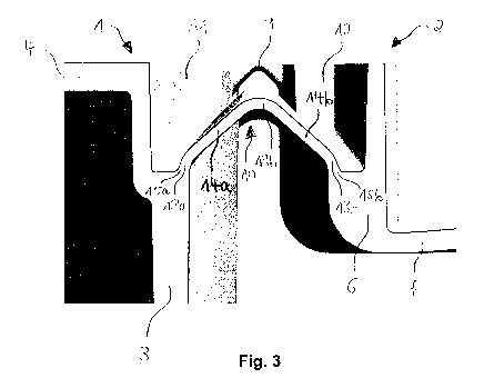
10 Fig. 3 shows a view corresponding to Fig. 2 of a tensioning band 10 of a
first realization of
a flap closure according to the first solution to the task. The tensioning
band 10 thereby
has three curved sections 13a, 13b, 13c, wherein a straight section 14a runs
between
curved sections 13a and 13b and a straight section 14b runs between curved
sections 13b
and 13c. The bending stresses which occur in the curved sections 13a, 13b, 13c
are thus
distributed over more curved sections and are therefore smaller per each
curved section.
At the same time, the course of the tensioning band 10 from its connection
point 15a with
the closure body 1 to its connection point 15b with the flap cover 2 is always
only curved
in the same direction viewed in cross section, and that being clockwise in the
view depicted
zo in Fig. 3. The average angle of curvature at the curved sections 13a,
13b, 13c can thereby
be kept smaller than would be with the same number of curved sections with
different
sections curving in opposite directions.
Due to the arrangement of the curved sections 13a, 13b, 13c, particularly a
portion of the
bending stress is shifted from the break-critical areas at the connection
points 15a, 15b to
the non-critical center of the tensioning band 10, whereby the bending stress
at the
connection points 15a, 15b is reduced.
Moreover, the tensioning band 10 does not or only barely projects radially
outwardly
beyond the lateral surfaces 3 and 6 in the closed state of the flap closure
and is thus barely
perceptible to the user.
Date Recue/Date Received 2020-12-30
CA 03105399 2020-12-30
WO 2020/007465
PCT/EP2018/068148
11
Fig. 4 shows a view corresponding to Fig. 2 of a tensioning band 10 of a
second realization
of a flap closure according to the first solution to the task. The tensioning
band 10 thereby
exhibits four curved sections 13a, 13b, 13c, 13d, wherein straight section 14a
runs
between curved sections 13a and 13b, straight section 14b runs between curved
sections
13b and 13c, and straight section 14c runs between curved sections 13c and
13d.
Due to the increased number of curved sections 13a, 13b, 13c, 13d, the bending
stress in
each of said curved sections 13a, 13b, 13c, 13d is further reduced.
Fig. 5 shows a view corresponding to Fig. 2 of a tensioning band 10 of a flap
closure
according to the second solution to the task.
The tensioning band 10 thereby exhibits a straight section 14a, 14b at the
respective
connection points 15a, 15b to the closure body 1 or to the flap cover 2
respectively between
which runs a curved section 13a. The straight sections 14a and 14b are of
different lengths.
However, the straight sections 14a and 14b could just as easily be the same
length. The
straight sections 14a and 14b are connected at such an angle to the closure
body 1 or to
the flap cover 2 respectively that the extension of the center lines T1, T2 of
the straight
sections 14a and 14b (corresponding to the tangents to these center lines if
they were
zo curved sections) runs exactly or nearly exactly through the axis of the
hinge 9. The distance
from the respective center line T1, T2 to the axis of rotation of the hinge 9
is thus almost
or exactly zero.
Fig. 6 shows the tensioning band 10 of the flap closure according to Fig. 5 in
a partially
open position of the flap cover 2. The opening position of the flap cover 2 is
thereby
selected such that the axis of the hinge 9 lies between the connection points
15a, 15b of
the tensioning band 10 to the closure body 1 or to the flap cover 2
respectively. In this
position, the tensile stress acting on the tensioning band 10 is at a maximum
and the
tensioning band 10 is fully stretched into a straight line. However, due to
the described
.. angular position of the connection points 15a, 15b of the tensioning band
10 to the closure
body 1 or to the flap cover 2 respectively, no or only slight bending stresses
occur at these
connection points 15a, 15b. Breaking or tearing of the tensioning band 10 thus
occurs less
frequently at these points.
Date Recue/Date Received 2020-12-30
CA 03105399 2020-12-30
WO 2020/007465
PCT/EP2018/068148
12
Fig. 7 shows a view corresponding to Fig. 2 of a further realization of a
tensioning band 10
of a flap closure according to the second solution to the task and Fig. 8
shows the
tensioning band 10 of the flap closure according to Fig. 7 in a partially open
position of
said flap cover 2.
The arrangement according to Figs. 7 and 8 substantially differs from the
arrangement
according to Figs. 5 and 6 in that, on the one hand, the tensioning band 10 in
the stretched
state (Fig. 8) does not run exactly through the axis of rotation of the hinge
9 in cross section
io but rather at a slight distance therefrom. On the other hand, the
extension of the center
lines T1, T2 of straight sections 14a and 14b does not run exactly through the
axis of the
hinge 9. However, the distance from the respective center line T1, T2 to the
rotational axis
of the hinge 9 is less than the thickness of the tensioning band 10 at the
respective
connection point 15a, 15b.
Otherwise, the arrangement and functioning of the tensioning band 10 in Figs.
7 and 8
largely correspond to those of the tensioning band 10 in Figs. 5 and 6 and
will therefore
not be described again.
Date Recue/Date Received 2020-12-30
CA 03105399 2020-12-30
WO 2020/007465
PCT/EP2018/068148
13
List of reference numerals
1 closure body
2 flap cover
3 lateral surface of the closure body
4 cap surface of the closure body
5 dispensing opening
6 lateral surface of the flap cover
7 cap surface of the flap cover
8 sealing plug
9 hinge
10 tensioning band
11 niche in the lateral surface of the closure body
12 niche in the lateral surface of the flap cover
13a - 13d curved section
14a - 14c straight section
15a, 15b connection points
T1, T2 tangents
Date Recue/Date Received 2020-12-30