Note : Les descriptions sont présentées dans la langue officielle dans laquelle elles ont été soumises.
STEREOLITHOGRAPHY DEVICE COMPRISING CARTRIDGE UNIT
The invention relates to a stereolithography device for producing a three-
dimensional object
by way of layered or continuous curing of a photosensitive substance under the
action of
specific radiation triggering the curing process, the device comprising:
- a support unit;
- a radiation source for generating the radiation triggering the curing
process; and
- a cartridge unit that can be positioned on the support unit and removed
therefrom.
Devices of this type are well-known. A stereolithography apparatus is used to
create a three-
dimensional body from a photosensitive substance by bonding layers or layer
information in
a layer by layer fashion or continuously. The invention is directed to the use
of an improved
cartridge system, which can be used in such an apparatus and surrounds the
object to be
produced.
The term stereolithography denotes a production process in which a light-
sensitive
substance that solidifies upon irradiation with light, and which in general is
a liquid
monomer formulation, is used to generate a three-dimensional body ("object")
having a
predefinable desired shape in a layer by layer fashion by generating geometric
layer
information, which can be generated, for example, by way of a digital mask or
by a moving
laser beam. The fundamental principle of stereolithography is also known by
terms such as
rapid prototyping, 3D printing and the like.
In addition to a controllable laser, pixel-based display units, incoherent
light sources, for
example in conjunction with controllable micromirrors (known as MEMS or DLP
chips), may
be used for the stereolithography process for projecting geometric layer
information into a
photosensitive substance, so as to cure ("develop") this substance in a layer
by layer fashion
or continuously on the bottom or another defined reference surface. The layer
information
may, in particular, be pixel-based. The reference surface (also referred to as
reference plane)
represents a defined surface area on which the curing of a layer of the
photosensitive
substance takes place; this may be the surface of the inside of the bottom or
lid or another
suitably defined surface area and, depending on the application, may have a
suitable solid,
flexible or liquid consistency. So as to separate the cured layer from the
reference surface,
Date Recue/Date Received 2021-01-14
2
this layer is first, which is to say prior to the first step of the generative
process, transferred
onto a support (for example, attached by way of a polymerization process),
which is able to
carry out a relative movement with respect to the focal plane, which may
coincide with the
upper face of the reference surface (for example the cartridge bottom). A next
method step
ensures that new material of the photosensitive substance is able to
subsequently flow
between the most recently generated layer and the reference surface; this may
take place by
way of a simple stroke movement, for example. The subsequent flow of
photosensitive
substance can then, in turn, be cured by way of exposure. These method steps
are repeated
until the object to be formed has been built according to the individual
projected pieces of
layer information.
The greatest problems of these methods lie primarily in the effective and
variable storage or
safekeeping of the photosensitive substance within the apparatus itself, as
well as in the
gentle separation of the individual layers from the reference surface, the
effective control of
the relative movement of the support of the generated layers or of the
generated object with
respect to the reference surface, and in handling of the apparatus and feeding
of new
photosensitive material into the apparatus in a manner that is as simple as
possible.
A variety of approaches are described in the prior art, which usually provide
open vat-
shaped receptacles for the photosensitive substance. In addition, cartridges
have been
described; however, these represent very complex, rigid and cumbersome
receptacles.
DE 10 2014 215 213 Al, for example, describes a receptacle in which a film
joined to a bottom
plate is provided, which is stretched downwardly by a non-transparent portion.
This film
may be deformed when the layers are lifted off so as to enable easier and
gentler detachment.
The receptacle is an assembled, complex assembly, which comprises, among other
things, the
bottom plate, a tensioning part protruding into the receptacle, and various
other parts, such
as the support itself, and has a complicated design.
Other approaches, such as in DE 101 19 817 Al and JP H06 246 838 A, use an
open, vat-
shaped geometry instead of a closed cartridge, and likewise include a
deformable film so as
to reduce the peel-off forces.
Date Recue/Date Received 2021-01-14
3
The known approaches have the disadvantage that the design of the cartridge
system and of
the vats themselves is very complex, and furthermore have disadvantages
regarding the
handling of the photosensitive substance, such as cleaning the vat, inserting
the vat in the
apparatus, establishing a precise amount to be added, as well as the exposed
liquid level in
the case of vat systems, the hazard of making direct contact with the
photosensitive
substance and/or of contaminating the apparatus itself during replenishment or
transfer.
Considerable disadvantages also arise during the insertion of a vat filled
with photosensitive
material and/or during removal of the vat since complicated clamping
mechanisms have to
be actuated, or the vat has to be pushed into holding devices. The problem of
contaminating
the apparatus and/or the operator, in particular of contaminating individual
apparatus
components or component groups, also exists during the removal of the
generated
component, requiring cleaning when switching to a different photosensitive
material, which
is a cumbersome and time-consuming process. Another disadvantage is that
conventional
approaches do not allow the apparatus to be operated under a certain
atmosphere or certain
atmospheric conditions. Cleaning the generated object also represents a
problem since,
during the removal of the support of the object from the apparatus, uncured
monomers
wetting the object can contaminate the apparatus as well as the installation
site of the
apparatus, in addition to a possible contamination of the user. Due to the
exposed liquid
level, the photosensitive substance is subjected to a certain aging process,
which changes the
chemical properties, and thus adversely affects the properties of the created
object, such as
the required biocompatibility.
It is the object of the invention described herein to create a
stereolithography device and a
cartridge unit for such a device, which overcome the above-described
disadvantages, and to
achieve a simplified, trouble-free, economical, preferably continuous, and
easy-to-document
generation of three-dimensional objects.
This object is achieved by a stereolithography device of the type mentioned at
the outset, in
which the cartridge unit comprises an interior space surrounded by a casing,
wherein at least
a portion of the casing is at least partially transparent to the radiation
triggering the curing
process, wherein according to the invention the casing of the cartridge unit
is deformable,
and the interior space surrounded by the casing has a volume that is at least
partially formed
by a receiving space for the photosensitive substance. A "receiving space"
shall be
understood to mean the space in which a quantity of the photosensitive
substance can be
Date Recue/Date Received 2021-01-14
4
accommodated for at least a duration of an irradiation and curing process and
is accessible to
the radiation.
The above-described object is also achieved by a cartridge unit for use in a
stereolithography
device of the aforementioned type, wherein the cartridge unit includes an
interior space
surrounded by a casing, wherein the casing of the cartridge unit is
deformable, and the
interior space has a volume that is at least partially formed by a receiving
space in which a
quantity of the photosensitive substance can be accommodated for at least a
duration of an
irradiation and curing process and is accessible to the radiation triggering
curing of the
photosensitive substance.
Instead of a substantially rigid cartridge of the known type, the approach
according to the
invention provides a cartridge in which the casing and the bottom are at least
partially
flexible and made of at least one material. The flexible design of the casing
allows the
cartridge case and, if necessary, the entire cartridge body to be deformed,
for example by
way of compression of the cartridge, facilitating a direct generation of the
layers and
adhesion of the layers to the object support (hereinafter 'support'), with
subsequent
separation of the layers from the reference surface, while the photosensitive
substance is
located within the cartridge at least partially during the building process.
As the number of
generated layers increases, the cartridge is stretched, or is compressed
(deformed) less,
allowing it to restore the original shape thereof upon insertion into the
apparatus after the
object to be generated has been completed, if so desired. It shall be noted
that a casing shall
be understood to mean those parts of the cartridge which delimit the interior
space with
respect to the outside; optionally present, additional components that can be
moved inside
the interior space, such as a ram, a doctor blade or valve parts, do not form
part of the casing
within the meaning of the present invention.
The invention thus also allows the photosensitive substance to be stored more
efficiently and
variably within the stereolithography apparatus, and the generated layers to
be gently
separated from the reference surface. Further advantages include the improved
and easier
control of the relative movement of the support of the generated layers or of
the generated
object with respect to the reference surface, and the simplified supply and
handling of
photosensitive material in the stereolithography apparatus.
Date Recue/Date Received 2021-01-14
5
The cartridge may furthermore be equipped with an information carrier, via
which the
quantity, the type, the state and process parameters can be inferred.
Accordingly, a cartridge
unit may include an information carrier which holds information regarding the
photosensitive substance, and in particular with respect to the quantity, type
and/or state
thereof, and/or process parameters of a process of producing a three-
dimensional object,
and/or transmits this to the stereolithography device, for example to a
control unit thereof.
The information carrier may be an imprint, a bar code, an RFID chip, a
magnetic strip or the
like, for example.
As mentioned above, it is advantageous when the cartridge unit can be
detachably inserted
into a stereolithography device of the kind disclosed herein. In an
advantageous refinement
of the invention, the cartridge unit may be detachably fastenable or fastened
to the object
support so as to facilitate a replacement of the cartridge.
The deformable area of the casing may have a one-piece design, and preferably
be made of a
flexible material, but may also have a multi-piece design if necessary. A
jacket portion of the
cartridge can be composed of a film tube (such as FEP or PTFE film), while the
bottom of the
cartridge, in which a transparent bottom part (which in the simplest case is
at least a piece of
glass), for example, is located, is a simple injection-molded part made of
suitable plastic
material, as is the closing top part of the cartridge. Depending on the
design, the bottom part
or the top part may include the reference surface.
Furthermore, the volume of the interior space may be formed predominantly, and
preferably
entirely, by the receiving space. The reference surface is located either on
the bottom (or the
cover surface) of the receiving space or is defined by a suitable surface in
the receiving space,
for example a membrane, an interface between two (for example layered) liquids
or at least
one photosensitive substance having different states in the receiving space.
The casing can,
advantageously, be realized so that the surrounded interior space has a volume
that remains
substantially the same during a deformation of the casing. In many
embodiments, the
deformability of the casing is realized such that a reversible compression
with respect to a
height of the cartridge unit is permitted. In most instances, compressive
deformation is what
is primarily desired, and in these cases the deformability may thus be limited
to such a
reversible compression. The compression (or, opposite thereto, the stretching)
may be
generated, for example, by a relative movement between a base plate of the
support unit and
Date Recue/Date Received 2021-01-14
6
a holding unit, which holds an end of the cartridge unit located opposite the
base plate; in
general, two ends of the cartridge unit are each held in the support unit by a
holding means,
and the compression or stretching of the cartridge unit takes place by a
relative movement of
the holding means with respect to one another.
In many embodiments, the casing may have a geometric shape that can be folded
onto itself.
In addition or as an alternative, the casing may comprise at least one
reference surface, which
may have a rigid, partially flexible or completely flexible design. It is
favorable when the
reference surface formed in the casing can be moved or deformed arbitrarily in
space.
The casing can, advantageously, be shaped so as to comprise a bottom, a top
part, and a
jacket connecting the bottom and the top part, wherein the jacket is
preferably deformable.
The bottom of the casing may be realized rigid or flexible, comprising at
least one layer,
and/or may be composed of multiple materials.
According to a further refinement aspect of the invention, the bottom of the
casing and/or
the jacket may comprise at least one perforatable area, preferably weakened
area(s), for
creating at least one opening for supplying or removing a photosensitive
substance and/or
for supplying or removing solvent into and/or out of the interior space.
The casing of the cartridge unit according to the invention may comprise a
closed bottom
that is impermeable to the photosensitive substance and formed of at least one
part, and side
walls. However, these may be designed to be permeable to gases or gas
mixtures. Within this
meaning, it is favorable when the aforementioned jacket is designed to be
pervious
(permeable) to gases or gas mixtures, and in particular to oxygen or air. The
bottom may also
be pervious to gas in this manner.
Furthermore, the casing may include a closable opening on the upper face
and/or on the
side, through which the photosensitive substance can be supplied to the
interior space and
removed therefrom. The casing can, in particular, also include lateral
openings or opening
extensions. The casing may comprise sealing elements for sealing the opening.
The casing
may thus comprise sealing elements on the upper opening and on the bottom
side.
Moreover, the opening may be closable by way of a closure element, which
preferably has a
Date Recue/Date Received 2021-01-14
7
one-piece design, wherein the closure element is preferably realized as a
support for the
cured layers of the photosensitive substance.
The one-piece or multi-piece cartridge may comprise geometric, mechanical or
magnetic
elements, which can be joined by way of a fixation to at least one element
that is able to carry
out a relative movement. Furthermore, an advantageous refinement of the
cartridge unit
may comprise a component that is movable in the interior space and guided in
the cartridge
unit by way of guides of a geometric, mechanical and/or magnetic nature.
Components
movable in the casing may be doctor blades, rams, flaps serving as valves or
the like, for
example.
One embodiment of the invention provides that the cartridge unit may comprise
a closure
part that upwardly delimits and closes the interior space, wherein this
closure part may be
replaceable and preferably have an overall rigid design. This closure part may
include
suitably shaped geometric clearances, which is to say recesses or openings, in
a surface
facing the interior space of the cartridge. Clearances of this kind allow
photosensitive liquid
from the capsule to penetrate into the interior space of the casing, for
example. Another
advantageous use of clearances is that of improving the adhesion of the three-
dimensional
object to the surface serving as the support. The closure part may moreover
have a one-piece
or multi-piece design. By way of a suitable geometric configuration of the
closure element, it
is possible to provide at least one area in which photosensitive resin or
resins can be stored
directly or indirectly.
Favorably, the closure element can make it possible to accommodate at least
one object filled
with photosensitive resin, which is preferably implemented so as to be
perforatable.
Accordingly, it may be favorable when the area is configured to accommodate a
receptacle
comprising a photosensitive substance, wherein preferably means for
perforating the
receptacle are provided.
In addition, the closure part can comprise at least one integrated plunger,
the stroke of which
allows the delivery of the photosensitive substance to be metered. The plunger
can moreover
comprise units for perforating or opening a receptacle present in the closure
part, and in
particular a receptacle comprising a photosensitive substance. The at least
one plunger may
Date Recue/Date Received 2021-01-14
8
thus be able to damage at least one bag-shaped element as a function of time
so as to release
photosensitive material.
Additionally, the plunger may comprise units for supplying a solvent and/or a
gas or a gas
mixture, and in particular nitrogen or air.
Moreover, the cartridge unit can, advantageously, comprise an oxygen-permeable
one-piece
or multi-piece bottom.
So as to facilitate a detachment of the produced three-dimensional object,
moreover a unit for
generating vibrations may be provided in the device according to the
invention.
The stereolithography device according to the invention may be provided for
the insertion of
one, two or more cartridges. In particular, a plurality of cartridge units may
be inserted in
the device.
Further details and preferences of the invention will be apparent from the
following
description of several exemplary embodiments, which are illustrated in the
accompanying
drawings and are not limiting to the invention. The drawings show the
following
schematically:
FIG. 1 shows a perspective view of a stereolithography device according to one
exemplary
embodiment of the invention;
FIG. 2 shows an exploded view of a cartridge unit, which can be inserted in
the device of
FIG. 1;
FIG. 2a shows the cartridge unit of FIG. 2 when assembled;
FIG. 3 shows a perspective view of a first embodiment of a cartridge closure
part comprising
a support and a capsule to be inserted therein;
FIG. 4 shows a longitudinal section of the closure part of FIG. 3;
FIG. 5 shows a perspective view of the closure part of FIG. 1, comprising an
inserted capsule;
FIG. 6 shows a longitudinal section of the closure part of FIG. 5;
FIG. 7 shows a perspective view of a second embodiment of a closure part;
FIG. 8 shows a longitudinal section of the closure part of FIG. 7;
Date Recue/Date Received 2021-01-14
9
FIG. 9 shows the closure part of FIGS. 7 and 8 with the stopper removed;
FIG. 10 shows an embodiment of a closure part assembled from multiple
components in a
perspective view;
FIG. 11 shows a longitudinal section of the closure part of FIG. 10 when
assembled;
FIGS. 12 and 13 show the closure part of FIGS. 10 and 11 with the plunger
actuated;
FIGS. 14a-14d show multiple variant embodiments of the casing of the cartridge
unit
according to the invention;
FIG. 15 shows a cartridge closure part comprising information carriers
provided thereon;
FIGS. 16a-16d illustrate, based on a sequence of four stages, the generation
of a cured layer
of the photosensitive substance, using a cartridge unit according to the
invention;
FIG. 17 shows a further embodiment of a cartridge system;
FIG. 18 shows another embodiment of a cartridge system; and
FIGS. 19a and 19b illustrate the replacement of a capsule of the closure part.
FIG. 1 shows an exemplary overview of an exemplary embodiment of a
stereolithography
apparatus 1 according to the invention for the generative fabrication of one
or more three-
dimensional objects 2 (FIGS. 16a-16d) from individual layers, which are cured
from a
photosensitive substance within a respective cartridge unit 5, 6. The
photosensitive substance
can be cured in a receiving space 4 within the cartridge unit 5, 6 by way of
actinic radiation.
Within the scope of the present disclosure, "actinic radiation" shall be
understood to mean (in
general electromagnetic) radiation that is suitable for triggering the desired
curing reaction
of the photosensitive substance, and in particular light radiation such as UV
light. The
photosensitive substance is generally liquid, wherein within the scope of the
present
disclosure the term "liquid" refers to liquids having arbitrary viscosity,
including
suspensions and pasty substances.
One or more cartridge units 5, 6 are held by way of respective associated
receiving units 75,
76 and are arranged on a base plate 77. Together with the receiving units 75,
76, including the
associated drives and optionally further components (not shown in FIG. 1), the
base plate 77
forms the support unit 7 of the invention.
Date Recue/Date Received 2021-01-14
10
A controllable light source 8 is arranged beneath the base plate 77, for
example, where it can
be horizontally positioned, preferably in two directions (X and Y), by way of
stepper motor-
operated linear actuators 81, 82. The light source 8 is configured to be
movable relative to the
at least one cartridge unit 5, 6 and, in this way, is positioned beneath the
cartridge unit 6 in
which a building process of an object 2 is to take place. In one variant, the
stereolithography
apparatus may also comprise a rotatably mounted mirror, by way of which the
light emitted
by the light source 8 can be directed via further deflection mirrors to
multiple cartridge units,
by deflection of the rotatably mounted mirror.
Each receiving unit 75, 76 is adjustable in terms of height with respect to
the base plate 77 or
the bottom of the cartridge system 5, 6, for example by way of a stepper motor
drive. The
receiving unit 75, 76 is advantageously configured to accommodate, center and
hold the
cartridge unit held therein in a certain position relative to the base plate;
preferably, the
receiving unit 75, 76 holds the top part (closure part) of the cartridge unit
and is thus able to
set the height of the cartridge unit, and compress the same, by way of a
movement with
respect to the base plate. The support unit 7 may furthermore comprise a
fastening element
74, for example a body that enables form-locked locking, for one or each of
the cartridge
units 5, 6, and the bottom part of the cartridge system 5, 6 can be secured,
by way of the
fastening element 74, at least for the duration of the development process. A
control unit 9,
for example a control computer, controls the movement of the units 75, 76, 81,
82, and the
sequences of the manufacturing process in the apparatus 1, including the
activity of the light
source 8, and, if necessary, the control unit also receives and processes
measuring and/or
sensor signals recorded by sensors in the cartridges 5, 6.
FIG. 2 shows a cartridge system 10 in an isometric exploded view (resolved in
the Z
direction) as one exemplary embodiment of a cartridge unit according to the
invention,
which can be inserted in the stereolithography device of FIG. 1; FIG. 2a shows
the cartridge
system 10 when assembled. The cartridge system 10 of the shown embodiment
comprises,
for example, a closure part 11, which may be identical, for example, to the
closure part
described hereafter in FIGS. 3-6, a casing 14 (for example, identical to the
casing 141 of FIG.
14a), and an additional bottom 15, which is preferably at least partially
transparent to actinic
radiation, a locking part 16, and a cartridge reinforcement part 17. Of
course, the closure
part, the casing, including the bottom, and the locking part may also be
implemented in
Date Recue/Date Received 2021-01-14
11
accordance with the other configurations disclosed herein, or further
embodiments which a
person skilled in the art will be able to discern within the scope of the
invention.
The locking part 16 is provided to additionally reinforce the casing 14, and
this component
16 can furthermore enable referencing, centering, force-fit and/or form-locked
fastening of
the at least partially flexible cartridge system 10 in the stereolithography
device 1 (FIG. 16).
Moreover, the locking part 16 prevents the lower cartridge area from bulging,
deforming,
bending and/or lifting off.
So as to be able to safely handle the at least partially flexible cartridge
system 10 outside and
inside the stereolithography apparatus 1, the cartridge system 10 may comprise
a cartridge
reinforcement part 17, which is designed, for example, at least in a half-
shell shape and
adapted to the geometry of the flexible casing 14 of the cartridge system 10.
A desired height
of the cartridge system 10 is defined by way of the cartridge reinforcement
part 17. The
cartridge reinforcement part 17 may also be configured so as to be easily
pulled from the
cartridge system 10, which can be achieved by way of a handle or a window, for
example.
The cartridge reinforcement part 17 is preferably configured to be able to
form a releasable
form-locked or force-fit joint with the locking part 16, the casing 14 and/or
the closure part
11 on at least one end, for example by clamping on the part 17 in the manner
of a clip.
FIG. 3 shows an oblique view from above and the side of a first embodiment of
the closure
part 11, comprising a support 102 of the generated layers (these are, as
mentioned, built up
on the bottom side of the support) into which furthermore at least one capsule
101 can be
inserted. The capsule 101 is still shown above the support 102 while not yet
inserted and not
perforated. At least one photosensitive substance, which may be a liquid
having any
arbitrary viscosity or pasty consistency, for example, is present in the
capsule 101. The
capsule 101 is closed by a capsule closure element 107. This closure element
107 may also be
realized as a pressure control valve or comprise such a valve. In one variant
(not shown) of
the capsule 101, this may comprise a pressure control valve itself.
FIG. 4 shows a sectional view (longitudinal section along the center axis) of
the capsule 101
and of the support 102. The (unperforated) capsule 101 comprises a certain
amount of the
photosensitive substance 3 having a starting fill level HO. The support 102
has at least one
opening 109 through which the photosensitive substance 3 exiting the capsule
101 can reach
Date Recue/Date Received 2021-01-14
12
the area beneath the support 102. In this embodiment, the capsule 101 comprise
one or more
areas 104 having a lower wall thickness on the bottom side 110 thereof. These
weakened
areas 104 are provided for perforation by projecting profiles 105 of the
support 102. The
projections 105 are located on the bearing surface 108 of the support for the
capsule 101 and
are designed, for example, as raised edges, which each surround an outwardly
directed
opening 109. When inserted in the support 102, the capsule 101 may be fixed by
one or more,
preferably engaging, holding means 106, which may be realized as resilient
detent hooks 106,
for example. The capsule 101 can thus be inserted from above in the support
102, while being
perforated at the same time.
It goes without saying that the capsule 101 may also be fixed in the support
102 in another
manner, for example by a bayonet catch or an additional part that is inserted
after the
capsule has been inserted and fixes the latter by engagement in the support;
the capsule 101
may also comprise a thread and be screwed into the support 102.
In one variant embodiment, the perforation may also take place by an
additional part
provided on the bearing surface 108, for example a blade or a syringe needle.
In a further
variant embodiment, the capsule has a multi-piece design, wherein the bottom
side 110 of
the capsule 101, at least in some regions, is formed of a material that is
easy to perforate, such
as a film. In this case it is possible to open the capsule 101 by perforating
the film or by
peeling the film off an area of the bottom side 110 covered by the film.
In a further embodiment, which is not shown, the support 102 comprises a
toothed ring or
teeth configured, for example, on the lateral surfaces (in the manner of a
spur gear). This
allows a rotation with respect to the bottom of the cartridge casing by a
small angle a (Greek
letter alpha) of a few angular degrees. As a result of this rotation, the
forces required for
detaching the produced object from the reference surface can be considerably
reduced.
FIG. 5 shows an oblique view of the support 102 comprising the capsule 101
inserted therein,
whereby the cartridge closure part 11 is formed.
FIG. 6 shows a sectional view (longitudinal section along the center axis) of
the capsule
closure part 11. Due to the perforation of the capsule 101 by the projections
105, the
photosensitive substance 3 is able to exit through the openings 109 provided
in the support
Date Recue/Date Received 2021-01-14
13
102. The fill level, as shown in FIG. 6, thus decreases from the starting fill
level HO (FIG. 4) to
a level h.
FIGS. 7 and 8 show an oblique view and a sectional view (corresponding to
those of FIGS. 5
and 6) of a second embodiment of the cartridge closure part 200, comprising a
support 202, a
lid 201 and a stopper 208. The support 202 contains the photosensitive
substance 3. An
opening 209 formed in the bottom surface of the support 202 is closed by the
stopper. The
stopper 208 comprises a grip element or a tab and is guided upwardly outward
through an
opening 207 of the lid 201; when inserted, the stopper seals the lid 201 and
the support 202 to
prevent photosensitive liquid 3 from exiting, wherein the sealing effect in
the openings 207,
209 may be achieved by integrated material-locking insertion, screwing or
additional
geometric profiles, as well as additional components, such as 0-rings, sealing
elements or the
like. The lid 201 closes the interior space of the support 202, for example by
way of a force-fit
and/or form-locked but sealed joint 210.
FIG. 9 shows how the photosensitive substance 3 exits the support 202 the
opening 209 on
the bottom after the stopper 208 has been removed. So as to facilitate the
exiting of the
photosensitive liquid 3, the geometry of the opening 209 may be suitably
shaped for this
purpose. In addition, the support 202 and the lid 201 may be coated on the
inside, on the
surfaces that come in contact with the photosensitive substance 3, with a
material that
ensures that as little of the photosensitive substance 3 as possible remains
in the interior
space of the support 202 after emptying. This may be achieved, for example, by
way of a
coating with FEP, PTFE (Teflon) or other materials that lower the surface
tension or wetting.
This variant enables easy re-filling of the cavity as well as easy cleaning.
Advantageously,
the stopper 208 may be configured such that reclosing and filling through the
opening 207 is
possible.
The stopper 208 could additionally comprise filling channels (not shown),
which allow the
cavity to the filled through the stopper; for this purpose, the filling
openings may be realized
as boreholes introduced from above, which meet lateral borehole openings
beneath the lower
end of the stopper (inverted L or T shape of the channel). As an alternative,
the lid 201 may
have a closable separate opening (not shown) suitable for filling.
Date Recue/Date Received 2021-01-14
14
FIGS. 10 and 11 show a third embodiment of the closure part 300, in which a
ram or plunger
301 is guided inside the support 302. The guidance of the plunger 301
preferably takes place
by way of guide elements 311 and 313, for example in the form of projections
or
protuberances 311, which engage in guide grooves 313 on the inside of the
support 302, and
which may thus be used for centering and guidance and as anti-turn elements.
The plunger
301 may furthermore be configured to be removable from the support 302. This
embodiment
allows the closure part 300 to be re-equipped with a bag-like receptacle 312
filled with a
photosensitive substance 3. The receptacle 312 is made at least partially of a
perforatable
material, which preferably is also impenetrable to light (such as a plastic
film or coated
aluminum foil). On the side facing the receptacle 312, the plunger 301
comprises elements
305 formed on the inner surface, for example in the form of needles, teeth or
blades, which
allow the bag-like receptacle 312 to be perforated in a targeted manner; in
addition or as an
alternative, the support 302 may also include such perforating means itself.
The perforation
may also take place in a controlled manner from the outside, for example by a
needle-like
body. In a further variant embodiment, the receptacle 312 filled with
photosensitive
substance 3 may comprise multiple sections, which are each filled with a
photosensitive
material. Due to an external, for example controlled, perforating body, the
individual section
can thus be perforated in a targeted sequence.
As is also apparent from FIGS. 10 and 11, the support 302 may furthermore be
configured so
as to be able to accommodate the bag-like object 312 and fix and/or center the
position
thereof. For this purpose, an area for accommodating the bag 312 may be
surrounded by a
rim or a number of tabs. The sectional view of FIG. 10 shows the multi-piece
closure part 300
comprising the bag-like object 312 held in the support 302 in the starting
position having the
plunger position h1 (measured as the distance from the upper edge of the
support 302).
The oblique view of FIG. 12 and the corresponding sectional view of FIG. 13
show the
closure part 300 in a state in which the plunger 311 is in the end position h2
thereof.
Proceeding from the starting position h1, any arbitrary position between the
positions h1 and
h2 of the plunger 301, and ultimately the end position h2, may be achieved by
the application
of an external force F. In one variant (not shown) where the plunger
comprises, for example,
a helical cam or a thread having a certain pitch rotatably in the support 302,
the plunger may
also be moved by applying a circumferential force (for generating a rotational
movement).
Date Recue/Date Received 2021-01-14
15
During the movement from the starting position h1 toward the position h2, the
bag 312 is
pierced by the perforating elements 305 and thereby opened. In the position h2
shown in
FIG. 12, the perforated bag 312' has dispensed the photosensitive substance 3,
which thus
flows into the interior space of the support 302 and from there exits the
support 302 through
openings 309 provided for this purpose. In a preferred embodiment, it may be
provided that
the plunger 301, in cooperation with the support 302, is configured to allow
not only the
perforation, but also a compression of the receptacle 312, and thus
substantially complete
emptying of the latter. It goes without saying that it is not essential for
the plunger 301 to be
a part of the closure part 300, and moreover the plunger may, in general, have
a multi-piece
design, which is to say may be divided into multiple sub-plungers, so that
these multiple
plungers can be moved independently of one another.
FIGS. 14a-14d show several examples of design variants 141, 142, 143, 144 of
the at least
partially flexible casing according to the invention of the cartridge unit
according to the
invention in schematic oblique views. The casing may have a single-piece
design, for
example, but may also be composed of two or more components. The basic
geometry of the
casing 14, 141-144 may have any arbitrary geometric configuration, depending
on the
desired field of application, surrounding an interior space 140; for example,
the casing may
have a cylindrical or prismatic shape, having a circular, oval, square or
rectangular outline,
and the edges of the basic polygon may additionally be rounded. The casing has
preferably a
cup-like basic shape, wherein it may comprise a bottom and a jacket. The
jacket forms a
lateral wall connecting the bottom and a top part, and the top part may form
part of the
casing or be formed by an additional component, such as a closure part 11,
200, 300, 400. In
particular, preferred configurations of the casing have a rotation-symmetrical
design or have
at least partially a box-shaped outline.
For example, the casing 141 may comprise a jacket having smooth outer and
inner surfaces,
as is shown in FIG. 14a. A more complex casing geometry is likewise possible,
as is shown in
FIGS. 14b and 14c. FIG. 14b shows bellows-like folds of the jacket of the
casing 142, allowing
easier folding of the casing 142. The casing 142 has a jacket geometry that,
in sections, has the
function of a bellows. In other examples (not shown), the jacket of the casing
may have a
conical, trapezoidal, converging design so as to facilitate folding of the
casing geometry. The
casing includes at least one opening and/or suitably designed appendages
and/or openings.
FIG. 14c shows one example of a casing 143 that is formed rotation-
symmetrically in a single-
Date Recue/Date Received 2021-01-14
16
piece in the base body and includes one or more openings via a bottom, into
which an
additional component 145 and/or a multi-layered bottom, which is composed of
different
materials, and optionally a closing transparent plate may be inserted, whereby
a cavity is
formed, which may be filled by way of the component 145, as will be described
in greater
detail hereafter based on FIG. 17. As an alternative, components formed on the
casing, such
as inlet/outlet connectors or the like, may also be realized in one piece with
the casing. In
addition, referencing FIG. 14d and the casing 144 shown therein, the casing
geometry may be
provided with at least one recessed and/or raised geometric profile 146 (such
as a groove or
a rib) in the lower area of the casing 144, by way of which an additional
bottom 15, 25 (FIGS.
2 and 17) can be fastened, which is at least partially transparent, for
example made of
Plexiglass, acrylic glass or float glass, to actinic radiation for curing the
photosensitive
substance and forms an additional cavity beneath the bottom of the casing 141-
144.
Furthermore, this profile may provide an orientation option and/or fastening
option for the
casing 144.
FIG. 15 shows an example of a cartridge closure part 500 having one or more
information
carriers 502, 503 provided on the outside thereof (the upper face of the lid
501 here), in which
information regarding the photosensitive substance, and in particular with
respect to the
quantity, type and/or state thereof, and/or process parameters of a process of
producing a
three-dimensional object is stored. Data can be transmitted from the
information carrier via
suitable transmission paths to the stereolithography device, for example the
control unit 9.
The information carrier may be an imprint, a bar code 503, an RFID chip 502, a
magnetic strip
or the like, for example.
FIGS. 16a-16d represent a sequence of individual stages or phases, which serve
to illustrate
the function of the cartridge unit according to the invention (based on the
example of a
cartridge system 10 of FIG. 2) in one possible embodiment of a
stereolithography apparatus 1
according to the invention. For the sake of improved clarity of the
illustration, only the light
source 8 of the apparatus 1 and the cartridge system 10 are shown in these
figures, while the
units for holding, positioning and potentially deforming
(compressing/stretching) the
cartridge system 10 are not shown. FIGS. 16a-16d illustrate the production of
a three-
dimensional object 2 based on a single build cycle for a layer Bn of the
object 2, of which
previously the layers B1 to Bn-1 have been generated. In the drawings of the
present
disclosure, the three-dimensional object 2 is shown as a component having an
inverted
Date Recue/Date Received 2021-01-14
17
pyramidal shape, which is merely intended to be exemplary and shall not be
limiting; it is
possible, of course, to generate a wide variety of shapes of three-dimensional
objects. The
build cycle for the layer Bn, using a photosensitive substance 3, comprises
the following
phases:
Phase 1: starting position at the height Al (FIG. 16a);
Phase 2: lowering the support to the height A2 (FIG. 16b), where A2 < Al;
Phase 3: exposing or generating the layer Bn (FIG. 16c);
Phase 4: lifting off the support (FIG. 16d), and optionally removing the cured
layer Bn from
the mold.
With this, an end position is reached, which corresponds to the starting
position (phase 1),
except having a height A3 > A2. The height A3 may correspond to or be
different from the
height Al prior to the shown build cycle. Frequently, A3 > Al since the size
of the
component increases.
FIG. 16a represents the starting situation, in which the capsule 111 is
already perforated,
from which the photosensitive substance 3 flows into the interior space 140 of
the cartridge
system 10, where it fills or covers the bottom of the casing 14, which
represents the receiving
space of the invention. In the starting position (phase 1) having the height
Al, n-1
component layers of the component 2 have already been generated, and the most
recently
formed layer Bn-1 is located in a position over the bottom of the casing 14.
Thereafter, as is shown in FIG. 16b, the upper part of the cartridge system 10
formed by the
closure part 11 is lowered, compressing the same. The closure part 11 is
advantageously
lowered until the layer Bn-1 makes contact (again) with the photosensitive
layer 3. The layer
Bn-1 is advantageously positioned so as to be located above the reference
surface 41 by the
desired layer thickness of the layer Bn to be formed. As the closure part 11
is being lowered,
photosensitive liquid 3 may continue to exit the capsule 111, if necessary,
wherein the liquid
photosensitive substance 3 still present beneath the layer Bn-1 is displaced
until the desired
layer thickness of the layer Bn is reached; in other words, the photosensitive
substance 3 fills
the gap between the layer Bn-1 and the reference plane 41 formed by the bottom
of the
casing 14 or, where necessary, a non-reactive phase 33 (see FIG. 17) of the
photosensitive
substance 3. According to the invention and in keeping with the configuration,
the
deformable casing 14 assumes a compressed, which is to say folded and/or
bulged, state.
Date Recue/Date Received 2021-01-14
18
In phase 3, illustrated in FIG. 16c, the new component layer Bn is cured by
way of actinic
radiation 80, such as UV light, which is emitted by the light source 8 and
focused onto the
areas of the layer Bn on the reference surface 41 to be developed. In this
process, analogous
to conventional stereolithography methods, the structure of the layer Bn is
generated by
selection of the exposed areas of the layer Bn.
In phase 4, the layer Bn thus cured in phase 3 is lifted off the bottom of the
casing 14 or the
phase 33 by way of a relative movement of the closure part 11, whereby the
newly formed
layer Bn is separated from the reference surface 41. The casing 14 is
elastically deformed in
keeping with the magnitude of the stroke of the upward movement, and more
particularly in
general is partially relaxed.
Fig. 17 shows another embodiment of a cartridge system 20, in which the casing
24, for
example, is substantially patterned after the casing 143 of FIG. 14c, in a
longitudinal sectional
view. A cavity 22, which is formed between the outer glass bottom 25 and the
bottom side 23
of the casing 24, is present beneath the casing 24. Due to the lateral
extensions of the casing
24 or other openings (not shown) provided for this purpose, the cavity 25 may
be flooded
with a fluid 19 (for example, oxygen or another gas suppressing the reaction)
or other
inhibitors (volume throughput V). A non-reactive phase 33 of the
photosensitive substance 3
forms due to the inhibitor penetrating through the permeable bottom of the
casing 24 into
the interior space 240 of the cartridge, in this embodiment the surface of the
non-reactive
phase, instead of the (inner) bottom surface of the casing 24, forming the
reference surface 42.
A reference surface 42 thus formed offers the advantage that the generated
layer of the
component 2 does not adhere to the bottom surface of the casing 24, and thus
the risk of the
bottom layer sticking and possibly tearing is avoided.
In this embodiment, or other shown embodiments, it is further possible to
apply a pressure
p1 to the interior space of the cartridge system, the pressure being larger or
smaller than the
ambient p0, which may take place through openings (not shown) provided for
this purpose
in the closure part 21 and/or the casing 24. The interior space of the
cartridge system can be
flooded with a specific inert gas (such as nitrogen), for example, which
prevents oxygen
inhibition of already formed layers, and thus positively influences the
mechanical strength of
the layers and the surface quality thereof.
Date Recue/Date Received 2021-01-14
19
FIG. 18 illustrates a further possible embodiment of the casing 34 (which is
designed
corresponding to the casing variant 144 of FIG. 14d) and a composition of the
cartridge
system 30. In this variant embodiment, the casing 34 comprises a discontinuous
bottom 344
(which is to say not solid), which thus includes an opening 18 (or a plurality
of such
openings). This opening is closed by way of an inserted plate- or leaf-shaped
component or
component combination 35. This component 35 may have a multi-piece design,
where
necessary, and ensures a closed interior space 340 of the cartridge system 30
and the upper
face thereof forms the reference surface. The component 35 may have a sandwich
design, for
example, which is at least partially transparent to the actinic radiation used
for curing the
photosensitive substance 3 and is at least partially permeable to gases; for
example, an elastic
film 31 (such as FEP film, Teflon film) may be formed on a support part 32
made of a
material such as microporous glass, which exhibits particularly good
permeability to the gas
or gas mixture used for forming a non-reactive phase 33 (see above with
respect to FIG. 17).
FIG. 18 furthermore shows another aspect of implementing the casing, based on
the variant
of the casing 144 of FIG. 14d, wherein the jacket of the casing 34 is formed
of multiple
segments (341, 342, 343), and the individual segments may have differing
material
properties. This allows a cartridge casing to be formed which comprises, for
example, areas
having differing flexibility and/or differing optical properties. A
segmentation of the jacket
can, of course, also be provided with any of the other embodiments shown
herein.
A further aspect of the invention is shown in FIGS. 19a and 19b, based on
sectional views of a
cartridge system 40 according to the invention, namely the replacement of a
capsule so as to
switch between different processing types, such as from a layer build process
to a cleaning
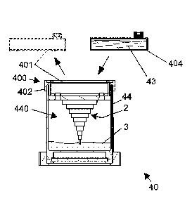
process. FIG. 19a shows the cartridge system 40, in which an object or a
component 2 was
built by way of the photosensitive substance 3, in accordance with the
sequences described
above; the photosensitive substance 3 is provided by a capsule 401, which is
inserted into the
support 402 of the cartridge system 40. By removing the capsule 401 and
replacing the same
by inserting a new capsule 404, which is compatible with the closure part 400
of this
exemplary embodiment, it is possible to supply a different substance instead
of the
photosensitive substance 3. For example, the capsule 404 can be filled with a
solvent 43, such
as isopropanol. As a result of the insertion of the capsule 404 and
perforation of the outer
casing of the capsule 404 in the course of the insertion into the interior
space of the support
402 of the closure part 400, the solvent 43 is released and can reach the
interior space 440 of
Date Recue/Date Received 2021-01-14
20
the cartridge system 40 through the openings of the closure part 400. As is
shown in FIG.
19b, the solvent 43 partially or completely fills the interior space of the
cartridge system 40,
thereby allowing the component 2 to be cleaned, and in particular
photosensitive substance 3
still adhering to the component 2 to be removed and/or residual photosensitive
substance 3
present in the interior space, which has not yet or only partially cured, to
be dissolved. Due
to the photosensitive substance 3 dissolving in the solvent 43, a solution or
mixture 13 is
formed in the interior space of the cartridge. This may now be drained via
openings in the
closure part 400 by tilting or inverting the cartridge 40. For example, the
mixture 13 may
flow out of the interior space 440 of the cartridge system 40 through the
openings in the
support 402 during removal of the capsule closure part 403. If desired, the
liquid may then
be replaced with new solvent. The cartridge unit may be configured so that a
dissolution of
the photosensitive substance 3 can be promoted by vibration, centrifuging,
shaking,
increasing the temperature or other suitable measures.
Similarly to what is shown in FIGS. 19a and 19b, it is also possible to switch
between
different types of photosensitive substances, for example when the object 2 is
to be composed
of different materials, and/or different liquids are desired for cleaning
and/or post-curing of
the object 2.
A replacement or a continuous exchange of the liquids may also be achieved by
supplying a
new (in general, a liquid or suspension-like) substance via a first opening in
the support 402
or the casing 44, which displaces the substance in the interior space; the
substance thus
displaced can drain via a second opening. Suitable pumps may be provided in
the supply
line of the first opening and/or the drain line of the second opening.
The above embodiments of the cartridge unit or stereolithography device
according to the
invention can, moreover, comprise the following aspects and refinements,
depending on the
application:
The cartridge unit can directly or indirectly comprise the photosensitive
substance and is
realized in one piece or assembled from multiple components. The casing may
have a three-
dimensional shape and is preferably realized in one piece, wherein the
deformable portion of
the casing, which is preferably a laterally peripheral jacket, may be made of
a flexible or
foldable material. The bottom of the casing may be at least partially
translucent and gas-
Date Recue/Date Received 2021-01-14
21
permeable, and may be made of a material suitable for this purpose, for
example silicone or a
multi-layer material composite comprising silicone, glass and/or plastic
layers, for example
having a sandwich-like composition. The stereolithography device is provided
with a light
source, which is preferably movable and displaceable in a controlled manner,
for selectively
exposing the photosensitive substance, and at least one object support (also
referred to as a
support holder or support for short). The object support is arranged inside or
outside the
cartridge unit and, if necessary, may be movable relative to the bottom of the
cartridge.
In another variant, the jacket portion of the cartridge may be made of a film
tube (such as
FEP or PTFE film), while the bottom of the cartridge and the closing top part
of the cartridge
are simple injection-molded parts made of suitable plastic material and/or
suitable multi-
layer composite materials. The costs of this variant embodiment are
considerably lower than
those of the silicone injection molding configuration, and the film would
additionally be
thinner and easier to deform.
The photosensitive material may be present in the cartridge in a receiving
space (or multiple
receiving spaces) formed therein, to which it has been added, for example,
before the
cartridge was inserted into the apparatus, or it may be supplied in one or
more receptacles,
which are inserted in the cartridge, for example in a receiving space within
the cartridge
body, the support (object support) or the casing itself, provided for this
purpose. The
support, which may also serve as the closure part and may have a single-piece
design or be
formed of multiple parts, may include at least one geometric cut-out in which
the
photosensitive substance or a receptacle therefor can be accommodated. This
cut-out may
additionally comprise a specially shaped surface or structures, or a component
having a
specially shaped surface or structures can be inserted therein, wherein this
surface or these
structures can cause a perforating effect on another body. The support or the
cut-out may
thus accommodate and/or store at least one photosensitive substance,
containing the same
directly or indirectly in a receptacle.
This eliminates complicated replenishing and dosing units and complicated
cleaning of the
support. A particular advantage is yielded with the cartridge system
(cartridge unit)
according to the invention due to the simple and contamination-free insertion
and removal
into and out of the stereolithography apparatus. It is possible to switch
quickly, and without
long cleaning and setup times, between different cartridges, which comprise
different
Date Recue/Date Received 2021-01-14
22
photosensitive substances, for example. It is thus also possible, for example,
to activate a
second cartridge in an apparatus during a build process that has already
started, so as to
increase the utilization of the apparatus. Moreover, since the substance
quantity within the
cartridge is known, it is possible to generate only a precisely defined number
or a precisely
defined object volume, depending on the requirement. It is thus possible, by
way of the
cartridge system according to the invention, to precisely define the life of
the photosensitive
substance, and consequently it is also possible to determine the object and
material
properties to be expected in the cured state, such as a desired
biocompatibility. The cartridge
system according to the invention can be easily removed from the apparatus,
including the
formed object on the support, and thereafter a post-processing system (for
example, for
cleaning and/or post-exposure) can be introduced, which is configured to
accommodate the
cartridge system and, possibly, introduce and/or remove cleaning agent, for
example a
solvent such as isopropanol, through openings or by perforating the cartridge
itself in
suitable locations.
Moreover, a specific atmosphere may be initiated in parts of the cartridge via
the same
and/or other suitable openings provided for this purpose. In this way, the now
cleaned or
partially cleaned cartridge, comprising the cleaned object on the support
located therein,
may serve as a cavity that is filled with inert gas. The casing is preferably
at least partially
translucent, and particularly preferably the casing and the bottom of the
cartridge are
translucent, and made of the same flexible material, such as silicone. Many
advantageous
embodiments are characterized in that the casing and the bottom of the
cartridge are realized
in one piece made from a translucent, flexible and chemically stable as well
as oxygen-
permeable material, such as silicone, and particularly preferably a liquid
silicone rubber
(LSR) material, wherein the closure part and potential other parts or portions
thereof, such as
the support and/or the plunger or plungers and/or the capsule or capsules
filled with
photosensitive material, may be made of a non-translucent material. The
support may
comprise at least one geometric cut-out, via which the photosensitive
substance can pass
through the plunger, or past the same, into the area of cartridge provided for
exposure, or to
the cartridge bottom, based on gravity or by way of pressure that is applied
by the support.
Since the invention makes a separate storage option for the photosensitive
substance in the
closure part or in a cavity formed in the closure part possible, the design
can preclude
swelling or diffusion of the substance into more sensitive areas of the
cartridge. It is
Date Recue/Date Received 2021-01-14
23
advantageous when the photosensitive substance is additionally enclosed in a
receptacle, for
example a bag-like receptacle, or a specifically shaped receptacle body, which
is preferably
located in the support or allows to be inserted therein. The closure part, or
more precisely
portions thereof, such as the rear side of the support, is configured, based
on the design
and/or based on the surface properties, to perforate a receptacle (for example
a bag)
comprising the photosensitive substance so as to thereby release the
photosensitive
substance. In another advantageous embodiment, a disposable capsule filled
with a
photosensitive substance can be pierced by a specially shaped portion of the
support,
whereby the photosensitive substance is released.
The cartridge system may be usable once or be designed to be used multiple
times. It may
thus be configured as a disposable system or be refillable.
Depending on the configuration, the cartridge unit according to the invention
enables a
simpler, more precise measurement of the gas mixture, lower amounts of gas, a
more precise
design of the gas volume flow since the amount of the photosensitive substance
is precisely
known, for example as a result of the capsule filling, safer and simpler
handling of the
photosensitive substance, a safe and more stable process, and prevention of
contamination.
Furthermore, the present invention dispenses with a completely or partially
gas-tight design
of the apparatus since the gas can be limited to the cartridge.
In a further favorable configuration, the casing of the cartridge comprises a
double bottom,
which may have a single-piece or multi-piece design. The portion closing the
casing (for
example downwardly), which forms the reference plane, and in the simplest case
also the
bottom of the cartridge system, may be composed of a non-flexible or only
partially flexible,
multi-layer bottom, which is transparent to actinic radiation and permeable to
specific gases
or gas mixtures. A supporting element, which is likewise permeable to gases,
may be present
beneath the cartridge casing.
The connection between the aforementioned bottom surface and the casing may be
configured to be gas-tight. The casing itself may comprise sealing elements,
such as special
beads. In another advantageous variant embodiment, the casing of the cartridge
may be
configured such that a double bottom is formed with respect to the casing only
after
insertion into the apparatus according to the invention, wherein the
transitional part is
Date Recue/Date Received 2021-01-14
24
configured completely or partially gas-tight. The cartridge unit itself may
moreover also be
stored in a gas-tight cladding in the apparatus, such as in a pipe. This
creates a geometrically
arbitrarily shaped cavity which, depending on the requirements and
possibilities of the
application, may comprise at least one access opening and/or at least one
discharge opening,
via which a specific gas or a gas mixture can be introduced, or was already
introduced. The
first bottom of the casing of the cartridge system, which is made of at least
one material that
is partially or entirely permeable to the gas or the gas mixture, is
preferably made of silicone
or a material combination comprising silicone and/or a permeable material,
such as PTFE or
glass. The closing portion of the casing can, as was already described,
likewise be made of a
microporous glass permeable to gas. In this way, a gas or gas mixture can be
supplied to the
inner volume of the cartridge and/or be discharged therefrom directly or
indirectly from
beneath. In a further embodiment, the cartridge system comprises a sensor or
sensing probe,
which is able to measure the diffusion of the gas or of the gas mixture in a
time-resolved
manner so as to thereby control the volume flow of the gas or of portions of a
gas mixture
over the duration of the process. The sensor may already be present in the
cartridge, such as
in the support. For example, the sensor may be introduced during insertion of
the cartridge
system and, where necessary, be positioned by way of a locking or centering
procedure of
the cartridge through a special, previously sealed opening or by perforation
of the cartridge.
It is favorable when the position of the sensor is selected such that the
sensor does not make
contact with the photosensitive resin, or when the sensor is configured such
that a
contamination does not result in a distortion of the measurement and in
increased measuring
uncertainty. The measuring of the atmosphere within the cartridge may take
place by way of
direct or indirect methods. A particularly advantageous measuring method is
one in which
the sensor or sensing probe is arranged outside the cartridge or the casing,
and enables a
measurement of the composition or of the gas concentration within the
cartridge; for this
purpose, the permeability of the casing itself may be utilized, so as to be
able to infer the gas
concentration in specific areas.
In further embodiments of the invention, different gases or gas mixtures may
be supplied
within the cartridge. For example, oxygen may be supplied from beneath through
the bottom
of the cartridge in a higher concentration than in the normal atmosphere, and
nitrogen may
be supplied from above through the support, so as to deliberately influence
the properties of
the photosensitive resin or of the processing thereof, and ultimately the
final properties of
the body that is created.
Date Recue/Date Received 2021-01-14
25
A person skilled in the art will, of course, be able to readily make a variety
of modifications
and additions to the embodiments of the invention disclosed herein, to the
extent these are
within the scope of protection of the claims below.
Date Recue/Date Received 2021-01-14