Note : Les descriptions sont présentées dans la langue officielle dans laquelle elles ont été soumises.
CA 03106370 2021-01-12
WO 2020/018814
PCT/US2019/042436
SYSTEMS AND METHODS FOR MONITORING AND/OR CONTROLLING
WOBBLE-PROCESSING USING INLINE COHERENT IMAGING (ICI)
RELATED APPLICATIONS
[0001] The present application claims the benefit of U.S. Provisional
Application
Serial No. 62/853,368 filed May 28, 2019, entitled Systems and Methods for
Monitoring
and/or Controlling Wobble-Welding Using Inline Coherent Imaging (ICI) and
claims the
benefit of U.S. Provisional Application Serial No. 62/700,606 filed July 19,
2018,
entitled "Wobble-Welding of Copper and Aluminum Allows with Inline Coherent
Imaging," both of which are fully incorporated herein by reference.
TECHNICAL FIELD
[0002] The present disclosure relates to monitoring and/or controlling
material
processing and more particularly, to systems and methods for using inline
coherent
imaging (ICI) to monitor and/or control material processing where a process
beam is
moved in a wobble pattern, such as wobble-welding
BACKGROUND INFORMATION
[0003] Laser welding of non-ferrous alloys for industrial applications is
expanding
but also presents some challenges. The low absorption of near-IR industrial
laser
wavelengths by aluminum and copper alloys, for example, resists initial
formation of a
keyhole, which may be necessary for efficient coupling of energy into the
workpiece.
Once a keyhole is established, the low viscosity of the melt (e.g., as
compared to ferrous
alloys) may result in reduced process stability and higher probability of
defects.
[0004] For challenging materials, such as aluminum, copper and other non-
ferrous
alloys, combining high-brightness fiber laser sources (e.g., single-mode/low-
mode) with
dynamic beam deflection (or beam wobbling) may be an effective approach to
precisely
control the distribution of laser power on the material surface, while
maintaining a high
level of radiative intensity at the light-matter interaction site. One "wobble-
welding"
technique for moving the beam more quickly and precisely includes using
movable
mirrors to provide wobble patterns with the beam, for example, as disclosed in
greater
detail in U.S. Patent Application Publication No. 2016/0368089, which is
commonly
1
CA 03106370 2021-01-12
WO 2020/018814
PCT/US2019/042436
owned and fully incorporated herein by reference. Such wobble-welding
processes may
improve process stability, particularly when welding copper and aluminum, and
may also
provide reduced spatter and porosity and an extra degree of control over the
finished
weld geometry. Thus, stable, repeatable and controllable results have been
demonstrated
with potential for widespread industrial application.
[0005] More detailed investigation into the keyhole and melt pool dynamics
that
yield these industrially-favorable finished results would be of value to
capitalize further
on the value of wobble-welding techniques. The extra degrees of freedom
introduced by
wobble-welding may, however, further complicate the already difficult task of
recording
keyhole dynamics using process monitoring with photodiode-based sensors or
high-
speed cameras.
SUMMARY
[0006] According to one aspect, a laser material processing system includes a
material
modification beam source for generating a process beam and a processing head
coupled to
the material modification beam source and including at least one process beam
scanning
actuator, for directing and moving the process beam according to a wobble
pattern in at
least one axis on a processing site of a workpiece. An inline coherent imaging
(ICI) system
optically coupled to the processing head and includes at least one imaging
beam scanning
actuator for positioning the imaging beam at least partially independently of
the process
beam. A control system controls at least the material modification beam
source, the process
beam scanning actuator, and the imaging beam scanning actuator. The control
system is
programmed to cause the processing head to scan the process beam in the wobble
pattern
and to cause the imaging beam scanning actuator to move the imaging beam to a
plurality
of measurement locations on the processing site in coordination with the
wobble pattern.
[0007] According to another aspect, a method is provided for monitoring a
wobble-welding
process. The method includes: directing a process beam and at least one
imaging beam
from an inline coherent imaging (ICI) system to a weld site of a workpiece;
moving the
process beam in a wobble pattern on the weld site of the workpiece; moving the
at least one
imaging beam at least partially independently from the process beam to a
plurality of
measurement locations on the weld site; and obtaining ICI measurements from
the plurality
of measurement locations as the process beam moves in the wobble pattern.
2
CA 03106370 2021-01-12
WO 2020/018814
PCT/US2019/042436
BRIEF DESCRIPTION OF THE DRAWINGS
[0008] These and other features and advantages will be better understood
by reading
the following detailed description, taken together with the drawings wherein:
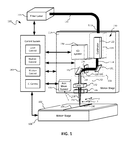
[0009] FIG. 1 is a schematic block diagram of a laser welding system that
provides
wobble welding patterns and is monitored using inline coherent imaging (ICI),
consistent
with embodiments of the present disclosure.
[0010] FIG. 1A is a schematic diagram of a focused laser beam with a
relatively small
range of movement provided by dual mirrors for purposes of wobbling,
consistent with an
embodiment of the present disclosure.
[0011] FIGS. 2A-2D are schematic diagrams illustrating different wobble
patterns
together with sample welds formed by those wobble patterns, consistent with
embodiments
of the present disclosure.
[0012] FIG. 3A is a micrograph of a standard weld, consistent with an
embodiment of
the present disclosure.
[0013] FIG. 3B is a micrograph of a weld formed using a wobble pattern.
[0014] FIGS. 4 and 5 are perspective views of a laser welding head with a
collimator
module, wobbler module, and core block module assembled together and emitting
a
focused beam, consistent with an embodiment of the present disclosure.
[0015] FIG. 6 is schematic block diagram of an ICI system that may be used
to monitor
wobble-welding, consistent with embodiments of the present disclosure.
[0016] FIG. 7 is a flow chart illustrating a method of monitoring wobble-
welding using
ICI, consistent with embodiments of the present disclosure.
[0017] FIG. 8 is an illustration of one example of monitoring wobble-
welding using
ICI by moving an imaging beam with a raster scan pattern across a weld site
and
encompassing a process beam wobble-pattern.
[0018] FIG. 9 illustrates averaged depth maps for welds in stainless steel
with a circular
wobble pattern and varying wobble diameters formed by raster scanning the
imaging beam
as shown in FIG. 8.
[0019] FIG. 10 is an illustration of another example of monitoring wobble-
welding
using ICI by moving an imaging beam to a plurality of fixed measurement
locations
along a process beam wobble-pattern.
3
CA 03106370 2021-01-12
WO 2020/018814
PCT/US2019/042436
[0020] FIG. 11 is a plot of the penetration depth as a function of weld
distance
measured at the fixed measurement locations as shown in FIG. 10.
[0021] FIG. 12 is a bar graph of the average penetration depth measured at
the fixed
measurement locations as shown in FIG. 10.
[0022] FIG. 13 is an illustration of a further example of monitoring
wobble-welding
using ICI by moving an imaging beam in a direction opposite the direction of
the process
beam along the wobble-pattern.
[0023] FIG. 14 is a plot of penetration depth as a function of distance
along a weld
measured as the imaging beam moves as shown in FIG. 13.
[0024] FIG. 15 shows plots of the mean penetration depth as a function of
rotation
angle at different welds speeds as the imaging beam moves as shown in FIG. 13.
DETAILED DESCRIPTION
[0025] Systems and methods, consistent with embodiments of the present
disclosure,
use inline coherent imaging (ICI) to monitor and/or control material
processing where a
process beam is moved in a wobble pattern, such as a wobble-welding process.
While at
least one process beam is moved according to a wobble pattern on a processing
site (e.g.,
a weld site) of a workpiece, an ICI system moves an imaging beam at least
partially
independently of the process beam to one or more measurement locations on the
wobble
pattern and obtains ICI measurements (e.g., depth measurements) at those
locations. The
ICI measurement(s) may be used, for example, to evaluate keyhole and/or melt
pool
characteristics during a welding process. Although the present application
describes
wobble welding processes, the systems and methods described herein may also be
used
with other material processing applications where a laser or other energy beam
is
wobbled or dithered during processing including, without limitation, additive
manufacturing, marking and material removal.
[0026] In one embodiment, the imaging beam is moved to scan the weld site
in a
scan pattern (e.g., raster scan) across multiple measurement locations
encompassing the
wobble pattern to form a depth map of the weld site. In another embodiment,
one or
more imaging beams are moved to one or more fixed measurement locations on the
wobble pattern. In a further embodiment, the imaging beam is moved along the
wobble
pattern in a direction opposite to the movement of the process beam. In yet
another
embodiment, the imaging beam is moved in a direction of the process beam along
the
4
CA 03106370 2021-01-12
WO 2020/018814
PCT/US2019/042436
wobble pattern but independently of the process beam, for example, to provide
dynamic
offset control and/or cyclic alignment correction.
[0027] As used herein, "wobble" refers to reciprocating movement of a
laser beam
(e.g., in at least one axis) and within a relatively small field of view
defined by a scan
angle of less than 100 or by a maximum beam angle displacement of 5 . In one
example, the ICI system may be used with a laser welding head with one or more
scanning actuators, such as movable mirrors, which performs welding operations
with
wobble patterns, for example, as described in greater detail in U.S. Patent
Application
Publication No. 2016/0368089, which is commonly-owned and fully incorporated
herein
by reference. The scanning actuators provide a wobbling movement of one or
more
beams within a relatively small field of view, for example, defined by a scan
angle of 1-
2 . The scanning actuators may include, without limitation, galvanometer
scanning
mirrors, polygon scanning mirrors, MEMS-based scanning mirrors, piezoelectric
scanning mirrors, diffraction-based beam scanners, rotating prisms, Potassium
Tantalum
Niobium Oxide (KTN) crystals, and other types of scanning mirrors or optics.
The laser
welding head may also include a diffractive optical element to shape the beam
or beams
being moved.
[0028] As used herein, inline coherent imaging (ICI) refers to a process
where an
imaging beam is directed to a workpiece together or "inline" with a process
beam for
purposes of measuring characteristics of the process and/or workpiece. The
term
"inline" does not require the imaging and process beams to be co-axial. The
imaging
beam may be co-axial with the process beam or may be offset or angled relative
to the
process beam. Embodiments described in the present disclosure may be used with
any
ICI systems, for example, as described in greater detail in U.S. Patent Nos.
8,822,875,
9,757,817 and 10,124,410, which are commonly-owned and fully incorporated
herein by
reference. The ICI system may be coupled to the welding head downstream of the
process beam scanning actuators and may include imaging beam scanning
actuators to
move the imaging beam independently of the process beam, as will be described
in
greater detail below. The scanning actuators may include, without limitation,
galvanometer scanning mirrors, polygon scanning mirrors, MEMs-based scanning
mirrors, piezoelectric scanning mirrors, diffraction-based beam scanners,
rotating prisms,
and other types of scanning mirrors or optics.
CA 03106370 2021-01-12
WO 2020/018814
PCT/US2019/042436
[0029] ICI may be used to monitor wobble welding in copper and aluminum
alloys
as well as other non-ferrous alloys. In particular, ICI allows direct,
geometrical keyhole
measurements and may be used to perform keyhole depth mapping within the
wobble
pattern to demonstrate periodic fluctuations in the keyhole corresponding to
position,
which are not always observable in a finished weld. Keyhole and melt pool
dynamics
may be examined for both revolving and common keyhole wobble welding
conditions.
ICI measurements may provide a unique window into the dynamics of welding
processes
that use dynamic beam deflection. ICI measurements, such as weld penetration
depth or
profiles and/or pre-process or post-process part measurements, may also be
used to
control processing parameters such as, for example, laser power or wobble
pattern.
[0030] ICI provides advantages over conventional photodiode-based sensors
or high-
speed cameras when applied to measurement of laser keyhole welding processes.
As
will be described in greater detail below, ICI delivers a secondary imaging
beam (e.g., an
infrared beam) through the process optics to take direct geometric
measurements of the
keyhole, melt pool, and surrounding material during the weld. ICI provides the
advantage of not being blinded by blackbody radiation or backscattered process
light and
is capable of directly measuring the penetration of the keyhole during a laser
weld. ICI
measurements are capable of micron-scale precision and microsecond-level
temporal
resolution. Using ICI to examine the behavior of the keyhole during wobble-
welding
yields new insights into the behavior of this type of welding process.
[0031] Referring to FIG. 1, a laser welding system 100 for wobble-welding
may be
monitored and/or controlled using an ICI system 150, consistent with
embodiments of
the present disclosure. The ICI system 150 may be used to monitor and/or
control the
wobble-welding by taking one or more ICI measurements at one or more locations
in the
weld site and along the wobble pattern, as will be described in greater detail
below.
Although the ICI system 150 is described in the context of a particular
embodiment of
the laser welding system 100, the ICI system 150 may be used with any type of
laser
welding systems for wobble-welding or with other material processing systems
where a
laser or energy beam is wobbled or dithered.
[0032] In the illustrated embodiment, the laser welding system 100
includes a laser
welding head 110 coupled to an output fiber 111 of a fiber laser 112 (e.g.,
with a
connector 111a). The laser welding head 110 may be used to perform welding on
a
workpiece 102, for example, by welding a seam 104 to form a weld bead 106. The
ICI
6
CA 03106370 2021-01-12
WO 2020/018814
PCT/US2019/042436
system 150 may be coupled to the laser welding head 110, for example, to a
camera port
or other optical port on the welding head 110.
[0033] The laser welding head 110 and/or the workpiece 102 may be moved or
translated relative to each other along the direction of the seam 104. The
laser welding
head 110 may be located on a motion stage 114 for translating the welding head
110
relative to the workpiece 102 along at least one axis, for example, along the
length of the
seam 104. In one example, the motion stage 114 is a multiple axis robot such
as an ABB
IRB-4400 six-axis robot and the materials or workpiece is clamped in a static
fixture.
Additionally, or alternatively, the workpiece 102 may be located on a motion
stage 108
for moving or translating the workpiece 102 relative to the laser welding head
110.
[0034] The fiber laser 112 may include an Ytterbium fiber laser capable of
generating a laser in the near infrared spectral range (e.g., 1060-1080 nm).
The
Ytterbium fiber laser may be a single mode or multi-mode continuous wave
Ytterbum
fiber laser capable of generating a laser beam with power up to 1 kW in some
embodiments and higher powers up to 50 kW in other embodiments. Examples of
the
fiber laser 112 include the YLR SM Series or YLR HP Series lasers available
from IPG
Photonics Corporation, such as the YLS-6000 fiber laser (1070 wavelength)
delivered
through a 100-um-core process fiber laser. The fiber laser 112 may also
include a multi-
beam fiber laser, such as the type disclosed in International Application No.
PCT/U52015/45037 filed 13 August 2015 and entitled Multibeam Fiber Laser
System,
which is capable of selectively delivering one or more laser beams through
multiple
fibers.
[0035] In the illustrated embodiment, the laser welding head 110 generally
includes a
collimator 122 for collimating the laser beam from the output fiber 111, at
least first and
second movable mirrors 132, 134 for reflecting and moving the collimated beam
116,
and a focus lens 142 for focusing and delivering a focused beam 118 to the
workpiece
102. In one example, the welding head 110 is an IPG D50 Wobble weld head with
a 150
mm collimator and a 300 mm final focusing optics (for a nominal focus diameter
of 200
um). The ICI system 150 may be coupled to the welding head 110 downstream of
the
movable mirrors 132, 134. In the illustrated embodiment, a fixed mirror 144 is
also used
to direct the collimated laser beam 116 from the second movable mirror 134 to
the focus
lens 142. The collimator 122, the movable mirrors 132, 134, and the focus lens
142 and
7
CA 03106370 2021-01-12
WO 2020/018814
PCT/US2019/042436
fixed mirror 144 may be provided in separate modules 120, 130, 140 that may be
coupled together, as will be described in greater detail below.
[0036] The movable mirrors 132, 134 are pivotable about different axes
131, 133 to
cause the collimated beam 116 to move and thus to cause the focused beam 118
to move
relative to the workpiece 102 in at least two different perpendicular axes 2,
4. The
movable mirrors 132, 134 may be galvanometer mirrors that are movable by galvo
motors, which are capable of reversing direction quickly. In other
embodiments, other
mechanisms may be used to move the mirrors such as stepper motors. Using the
movable mirrors 132, 134 in the laser welding head 110 allows the laser beam
118 to be
moved precisely, controllably and quickly for purposes of beam wobbling
without
having to move the entire welding head 110 and without using rotating prisms.
[0037] In an embodiment of the welding head 110, movable mirrors 132, 134
move
the beam 118 within only a relatively small field of view (e.g., a maximum
beam
displacement at the workpiece of 30 mm) by pivoting the beam 118 within a
scan angle
a of less than 10 (or with a maximum beam angle displacement of 5 ) and
more
particularly a scan angle of about 1-2 , as shown in FIG. 1A, thereby allowing
the beam
to wobble. In contrast, conventional laser scan heads generally provide
movement of the
laser beam within a much larger field of view (e.g., larger than 50 x 50 mm
and as large
as 250 x 250 mm) and are designed to accommodate the larger field of view and
scan
angle. Thus, the use of the movable mirrors 132, 134 to provide only a
relatively small
field of view in the laser welding head 110 is counter-intuitive and contrary
to the
conventional wisdom of providing a wider field of view when using galvo
scanners.
Limiting the field of view and the scan angle provides advantages when using
galvo
mirrors in the welding head 110, for example, by enabling faster speeds,
allowing use
with less expensive components such as lenses, and by allowing use with
accessories
such as air knife and/or gas assist accessories.
[0038] Because of the smaller field of view and scan angle in the example
embodiment of the welding head 110, the second mirror 134 may be substantially
the
same size as the first mirror 132. In contrast, conventional galvo scanners
generally use
a larger second mirror to provide for the larger field of view and scan angle
and the
larger second mirror may limit the speed of movement in at least one axis. A
smaller
sized second mirror 134 (e.g., about the same size as the first mirror 132) in
the welding
8
CA 03106370 2021-01-12
WO 2020/018814
PCT/US2019/042436
head 110 thus enables the mirror 134 to move with faster speeds as compared to
larger
mirrors in conventional galvo scanners providing large scan angles.
[0039] The focus lens 142 may include focus lenses known for use in laser
welding
heads and having a variety of focal lengths ranging, for example, from 100 mm
to 1000
mm. Conventional laser scan heads use multi-element scanning lenses, such as
an F-
theta lens, a field flattening lens, or a telecentric lens, with much larger
diameters (e.g., a
300 mm diameter lens for a 33 mm diameter beam) to focus the beam within the
larger
field of view. Because the movable mirrors 132, 134 are moving the beam within
a
relatively small field of view, a larger multi-element scanning lens (e.g., an
F-theta lens)
is not required and not used. In one example embodiment of the welding head
110
consistent with the present disclosure, a 50 mm diameter plano convex F300
focus lens
may be used to focus a beam having a diameter of about 40 mm for movement
within a
field of view of about 15 x 5 mm. The use of the smaller focus lens 142 also
allows
additional accessories, such as air knife and/or gas assist accessories, to be
used at the
end of the welding head 110. The larger scanning lenses required for
conventional laser
scan heads limited the use of such accessories.
[0040] Although the exemplary embodiment of the laser welding head 110
includes
two movable mirrors 132, 134, other types and numbers of scanning actuators
may also
be used to provide the wobble pattern. Other optical components may also be
used in the
laser welding head 110 such as a beam splitter for splitting the laser beam to
provide at
least two beam spots for welding (e.g., on either side of the weld).
Additional optical
components may also include diffractive optics and may be positioned between
the
collimator 122 and the mirrors 132, 134.
[0041] A protective window 146 may be provided in front of the lens 142 to
protect
the lens and other optics from the debris produced by the welding process. The
laser
welding head 110 may also include a welding head accessory, such as an air
knife for
providing high velocity air flow across the protective window 146 or focus
lens 142 to
remove the debris and/or a gas assist accessory to deliver shield gas
coaxially or off-axis
to the weld site to suppress weld plume. Thus, the laser welding head 110 with
movable
mirrors is capable of being used with existing welding head accessories.
[0042] In the illustrated embodiment, the ICI system 150 is optically
coupled to the
laser welding head 110, for example, downstream of the mirrors 132, 134. The
ICI
system 150 generates an imaging beam 152 that is directed in-line with the
process beam
9
CA 03106370 2021-01-12
WO 2020/018814
PCT/US2019/042436
118. The fixed mirror 144 may be a dichroic mirror that reflects the process
beam 118
and allows the imaging beam 152 to pass through. The ICI system 150 includes
one or
more scanning actuators (not shown) to move the imaging beam 152 to the one or
more
measurement locations at the weld site and on the wobble pattern, as will be
described in
greater detail below. In one example, the ICI system 150 includes an IPG LDD-
700 ICI
system incorporating a secondary pair of galvanometer scanner mirrors,
allowing the
imaging beam to be positioned independently of the process beam. In other
embodiments, the ICI system 150 may be optically coupled upstream of the
mirrors 132,
134.
[0043] The illustrated embodiment of the laser welding system 100 further
includes a
control system 160 for controlling the fiber laser 112, the positioning of the
movable
mirrors 132, 134, and/or the motion stages 108, 114, for example, in response
sensed
conditions in the welding head 110, a detected location of the seam 104,
and/or
movement and/or a position of the laser beam 118. The control system 160 may
also
monitor and/or control the welding operation by receiving data from the ICI
system 150,
for example, representing depth measurements along the weld site.
[0044] The control system 160 may control the fiber laser 112, for
example, by
shutting off the laser, changing the laser power, or adjusting any other
adjustable laser
parameter. The control system 160 may also control the laser parameters (e.g.,
laser
power) in response to movement or a position of the beam 118 without turning
off the
laser 112. If one of the movable mirrors 132, 134 moves the beam 118 out of
range or
too slowly, the control system 160 may reduce the laser power to control the
energy of
the beam spot dynamically to avoid damage by the laser. The control system 160
may
further control selection of laser beams in a multi-beam fiber laser.
[0045] The control system 160 may control one or both of the movable
mirrors 132,
134 to provide the wobble movement during welding, as described in greater
detail
below. The control system 160 may also control the scanning actuators in the
ICI system
150 to control movements and/or positioning of the imaging beam 152 on the
weld site
as described below. The control system 160 may also include data processing
systems to
correct ICI measurements. The control system 160 may further include a record
generator for generating records of the ICI measurements and a quality
judgment system
for performing quality analysis of welded parts.
CA 03106370 2021-01-12
WO 2020/018814
PCT/US2019/042436
[0046] The control system 160 thus includes laser control, wobble control,
motion
control and ICI control working together to control both the wobble-welding
process and
monitoring of the wobble-welding process. The control system 160 may include,
for
example, hardware (e.g., a general-purpose computer or microcontroller) and
software
known for use in controlling fiber lasers and galvo mirrors. Existing galvo
control
software may be used, for example, and modified to allow the galvo mirrors to
be
controlled as described herein.
[0047] The laser welding system 100 may also include an auxiliary
measurement
system 170 including auxiliary sensors such as visible and/or IR-sensitive
photodiodes,
and/or cameras, some of which may be coupled to the welding head 110 by way of
optical fibers. The auxiliary measurement system 170 may be configured to
measure
process radiation, for example, within a spectral band of 100 nm to 20 um. The
auxiliary
measurement system 170 may include optical elements, such as apertures,
lenses,
scanning mirrors, optical fibers (some of which may be coupled to the process
laser, or
ICI system itself), to perform spatially localized measurements relative to
the process
beam and/or the measurement beam. Examples of auxiliary sensors are described
in
greater detail in U.S. Patent No. 10,124,410, which is incorporated herein by
reference.
One or more outputs from the auxiliary measurement system 170 may be used to
dynamically offset the imaging beam from the process beam at the workpiece
surface
according to a position of the process beam within the wobble pattern during a
welding
process. The auxiliary measurement system 170 may be configured to perform the
spatially localized measurement at a measurement location dynamically offset
from the
process beam based on at least one output from the ICI system.
[0048] FIGS. 2A-2D illustrate examples of cyclical or repeating wobble
patterns that
may be used to perform stir welding of a seam together with sample welds
formed
thereby. FIG. 2A and 2B show a clockwise circular pattern, FIG. 2B shows a
linear
pattern, FIG. 2C shows a figure 8 pattern, and FIG. 2D shows an infinity
pattern.
Although certain wobble patterns are illustrated, other wobble patterns are
within the
scope of the present disclosure including, without limitation, spiral
patterns. One
advantage of using the movable mirrors in the laser welding head 110 is the
ability to
move the beam according to a variety of different wobble patterns.
[0049] FIGS. 3A and 3B illustrate a comparison of standard weld with a
weld
formed by a wobble pattern. The laser welding systems and methods described
herein
11
CA 03106370 2021-01-12
WO 2020/018814
PCT/US2019/042436
may be used to improve welding with materials, such as titanium, that are
typically
difficult to weld.
[0050] FIGS. 4 and 5 illustrate an example embodiment of a scanning laser
welding
head 410 in greater detail. Although one specific embodiment is shown, other
embodiments of the laser welding head and systems and methods described herein
are
within the scope of the present disclosure. As shown in FIGS. 4 and 5, the
laser welding
head 410 includes a collimator module 420, a wobbler module 430, and a core
block
module 440. The wobbler module 430 includes the scanning actuator(s) such as
the first
and second movable mirrors as discussed above and is coupled between the
collimator
module 420 and the core block module 440.
[0051] The collimator module 420 may include a collimator (not shown)
with a fixed
pair of collimator lenses such as the type known for use in laser welding
heads. In other
embodiments, the collimator may include other lens configurations, such as
movable
lenses, capable of adjusting the beam spot size and/or focal point. The
wobbler module
430 may include first and second galvanometers (not shown) for moving galvo
mirrors
(not shown) about different perpendicular axes. Galvanometers known for use in
laser
scanning heads may be used. The galvanometers may be connected to a galvo
controller
(not shown). The galvo controller may include hardware and/or software for
controlling
the galvanometers to control movement of the mirrors and thus movement and/or
positioning of the laser beam. Known galvo control software may be used and
may be
modified to provide the functionality described herein, for example, the seam
finding, the
wobbler patterns, and communication with the laser. The core block module 440
may
include a fixed mirror (not shown) that redirects the beam received from the
wobbler
module 430 to a focus lens and then to the workpiece. The ICI system may be
coupled,
for example, to the core block module 440 and the fixed mirror in the core
block module
440 may be a dichroic mirror allowing the reflected imaging beam to pass back
through
to the ICI system, as will be described in greater detail below.
[0052] FIGS. 4 and 5 show the assembled laser welding head 410 with each
of the
modules 420, 430, 440 coupled together and emitting a focused beam 418. A
laser beam
coupled into the collimator module 420 is collimated and the collimated beam
is directed
to the wobbler module 430. The wobbler module 430 moves the collimated beam
using
the mirrors and directs the moving collimated beam to the core block module
440. The
12
CA 03106370 2021-01-12
WO 2020/018814
PCT/US2019/042436
core block module 440 then focuses the moving beam and the focused beam 418 is
directed to a workpiece (not shown).
[0053] FIG. 6 shows an example of an ICI system 650 including an
interferometer
configuration and using low coherence interferometry to monitor a wobble
welding
system as described above. The illustrated embodiment uses a Michelson-style
interferometer; however, ICI systems with other interferometry configurations,
such as
Mach-Zehnder, may also be used with a wobble-welding system and are within the
scope
of the present disclosure.
[0054] The ICI system 650 includes an imaging beam source 652 for
generating one
or more imaging beams 652 and a splitter / combiner 654 for splitting the
imaging
beam(s) 652 such that at least one imaging beam component 652a is directed
toward a
workpiece 602 (i.e., applied to a sample arm 656) and at least one imaging
beam
component 652b is directed toward a reference mirror 657 (i.e., applied to a
reference
arm 658). In the illustrated embodiment, the imaging beam component 652a
directed
toward the workpiece 602 passes through a dichroic mirror 644 that reflects a
process
beam 618 used to perform the wobble welding. Other combining optics may also
be
used to combine the imaging beam component 652a with the process beam 618
while
allowing the reflected imaging beam component 652a to pass back toward the
combiner
654.
[0055] The reflected imaging beam components from the workpiece 602 and
the
reference mirror 657 are then combined by the splitter/combiner 654 to provide
a
combined signal as an interferometry output. The ICI system 650 further
includes a
signal detector 655, such as a high speed spectral detector, to receive and
detect the
combined signal formed from the reflected imaging beam components 652a, 652b,
thereby producing an interferogram from the interferometry output. The
interferogram
may be provided to an interferogram processor 661 to process the interferogram
and
calculate measurements (e.g., depth measurements) therefrom. The interferogram
processor 661 may be part of the ICI system 650 or the control system 160
shown in
FIG. 1.
[0056] In this embodiment, the ICI system 650 further includes one or more
imaging
beam scanning actuators 659, such as a 2-axis galvo scanner or other active
deflection
devices, for scanning the imaging beam component 652a independently of the
process
beam 618. The scanning actuators 659 may be used, for example, to scan the
imaging
13
CA 03106370 2021-01-12
WO 2020/018814
PCT/US2019/042436
beam component 652a to remain substantially aligned with the process beam 618
as it
moves in a wobble pattern. The scanning actuators 659 may also be used to scan
the
imaging beam component 652a in various scan patterns encompassing the wobble
pattern of the process beam 618, as will be described in greater detail below.
In other
embodiments, the ICI system 650 may include multiple sample arms 656 and/or
multiple
reference arms 658. For example, multiple reference arms 658 with different
optical
path lengths may be used to account for changes in optical path length when
the imaging
beam component 652a is scanned.
[0057] Referring to FIG. 7, a method of monitoring wobble welding using
ICI is
shown and described. The method includes directing 710 at least one process
beam (e.g.,
process beam 118, 618) and at least one imaging beam (e.g., imaging beam 152,
652a)
from an ICI system to a weld site. The process beam is moved 712 in a wobble
pattern
on the weld site, for example, as described above. The imaging beam is moved
714 at
least partially independently from the process beam to one or more measurement
locations on the weld site including, for example, on the wobble pattern. ICI
measurements are obtained 716 from the one or more measurement locations as
the
process beam moves in the wobble pattern. The imaging beam may be moved to
obtain
the ICI measurements at different locations allowing various aspects of the
wobble-
welding to be evaluated including, for example, keyhole and/or melt pool
characteristics,
as described in greater detail below. The imaging beam may also be moved along
the
same wobble path and substantially aligned with the process beam. The imaging
beam
may also be dithered or wobbled locally at the one or more measurement
locations.
[0058] The ICI measurements may also be used to control the wobble-welding
process, for example, by adjusting one or more processing parameters and/or
the wobble
movement of the process beam. Examples of control include feedback control,
for
example, as described in in U.S. Patent Nos. 8,822,875, 9,757,817 and
10,124,410,
which are commonly-owned and fully incorporated herein by reference.
[0059] Referring to FIGS. 8 and 9, one embodiment of monitoring a wobble-
welding
process using ICI includes moving the imaging beam 152 to raster scan the weld
site in a
scan pattern across multiple measurement locations encompassing the wobble
pattern to
form a depth map of the weld site. In one example, the process beam 118 was
wobbled
with a circular pattern and moved in welding direction 3 to carry out linear
bead-on-plate
welds in stainless steel (304) coupons. During each weld, the ICI measurement
beam or
14
CA 03106370 2021-01-12
WO 2020/018814
PCT/US2019/042436
imaging beam was raster-scanned through a square grid pattern measuring 1.5 by
1.5
mm, centered on the process beam axis (when static). Depth measurements from
each
point in the grid pattern were combined to form asynchronous three-dimensional
images
of the weld site. Process parameters were held constant according to Table 1
below,
except for the wobble pattern diameter, which was varied from Oum (equivalent
to a
fixed-optic weld) to 500 um. Three-dimensional images of successive welds were
combined by calculating the mean depth at each location in (x,y) to build up a
representative depth map of the material surface including virgin steel,
keyhole, and melt
pool.
Table 1: Process parameters for keyhole shape
wsmsri molls
Parameter Value
Laser Power 15010 W
lYlaterial feed at SO mrw's
Laser Spot Size 200 pra
Wobble frequency 500 Hz
Wobble diameter 0 500 pm (varied)
Wobble gi c Circular
[0060] FIG. 9 shows averaged depth maps for welds in stainless steel with
varying
wobble diameters (e.g., no wobble, 100 um, 200 um, 300 um, 400 um and 500 um)
where welding direction is from right to left in the images. Each map is a
combination
of five successive three-dimensional images acquired during different welds
with
identical parameters. A qualitative change in the depth map can be seen
between the 100
um and 200 um wobble diameters. For fixed-beam welding, and for the 100 um
beam
wobbled case, the process produces a localized keyhole which is deep at the
center of the
image.
[0061] At 200 um diameter and above, the melt pool begins to encroach on
the
center of the wobble pattern (e.g., as indicated by measured depths similar to
the surface
of the material). Above this diameter, the deeper measurements of the keyhole
fall into a
ring-shaped distribution. In this regime, the keyhole traces out a circular
pattern within a
larger melt pool, following the process beam through its motion. In other
words,
increasing the wobble diameter to the focused diameter of the process beam
resulted in a
transition of the keyhole depth distribution from a single localized keyhole
area to a
revolving keyhole with a high central region of melt, level with the material
surface.
CA 03106370 2021-01-12
WO 2020/018814
PCT/US2019/042436
[0062] These results are intuitive when considering the diameter of the
process
beam. For these experiments, the nominal 1/e^2 beam diameter at focus was 200
um.
When the wobble diameter is increased to match the beam diameter, there is no
longer an
appreciable area of intensity overlap at center throughout each revolution of
the process
beam. This results in a deficit of evaporation recoil pressure on the process
axis when
compared to smaller-diameter wobble patterns, and causes the keyhole to
transition to a
distinct orbiting motion. For wobble diameters smaller than the beam diameter,
the
keyhole depth distribution appears to be more similar to that of a fixed-beam
keyhole.
There may still be some small-scale orbiting of the keyhole following the
process beam
in this regime, which would not be visible in the images shown in FIG. 9. This
could
affect melt pool dynamics and overall process stability in a manner not
possible when
using a larger-diameter beam with an equivalent time-averaged intensity
distribution.
[0063] Referring to FIGS. 10-12, another embodiment of monitoring a wobble-
welding process using ICI includes moving the ICI imaging beam 152 to one or
more
fixed locations along the wobble pattern to obtain fixed ICI measurements at
the
location(s). In one example, the process beam 118 was wobbled with a circular
wobble
pattern and moved in welding direction 3 to produce linear bead-on plate welds
in copper
(110) with a goal of observing and comparing keyhole depth oscillation
stability at
specific fixed points within the wobble pattern. Keyhole measurements were
acquired
continuously at fixed locations in the wobble pattern for the entire duration
of each weld.
Different measurement positions were examined during successive welds with
identical
parameters according to Table 2 below.
Tabie 2: Process parameters for keyholc staby at
fixed noints
A
Parameter
Laser Power 3000 W
Material teed rate 50 inn's
Laser spot size 200 pm
Wobble frequency 500 Hz
Wobble diameter 500 um
Wobble shaps_1...., Circular
[0064] In this example, static ICI depth measurements were acquired at the
four
cardinal points (e.g., 152a-d) around the circular wobble pattern. The two
points (e.g.,
152a, 152b) along the axis parallel to the welding direction will be referred
to as leading
16
CA 03106370 2021-01-12
WO 2020/018814
PCT/US2019/042436
(152a) and trailing (152b), and the two points (e.g., 152c, 152d) along the
axis
perpendicular to the welding direction 3 will be referred to as fast (152c)
and slow
(152d). The motion of the process beam combined with the travel speed of the
head
relative to the part creates an asymmetry in the local travel speed of the
beam between
the fast and slow sides of the wobble pattern. Based on the wobble parameters,
the
circumferential speed of the process beam in the frame of reference of the
process head
was 785 mm/s. On the fast side of the wobble pattern, the process beam
travelled at 835
mm/s in the forward welding direction 3 (relative to the material), while on
slow side of
the wobble pattern, the beam travelled at 735 mm/s toward the rear of the
weld.
[0065] Depth data acquired in this manner includes measurements from the
bottom
of the keyhole when the process beam 118 crosses through the measurement beam
(152a-d), and measurements from the surface of the melt pool at other times.
The depth
data was reduced to a set of keyhole minima by searching for a local minimum
within
each expected crossing interval of the two beams. FIG. 11 shows resulting
keyhole
depths for all four measurement locations (i.e., the leading, trailing, slow,
and fast edges
of the wobble pattern) during different bead-on-plate welds in copper with
identical
parameters. FIG. 12 shows mean depths and standard deviations for each of
these
measurement locations on the cardinal points of a circular wobble pattern.
[0066] Each of the four depth measurement sets in FIG. 11 displays its own
characteristic depth and stability traits. The leading and trailing
measurements show a
marked difference in penetration depth (e.g., approximately 400 um). When the
keyhole
moves across the trailing edge of the wobble pattern (closest to the majority
of the melt
volume), it reaches greater penetration depths than it does on the leading
edge of the
pattern. The slow and fast edges of the pattern exhibit differences in both
depth and
stability. The slow edge of the wobble pattern is observed to reach greater
depths on
average than the fast edge of the pattern. This increased penetration on the
slow edge is
accompanied by a greater variability of the depth measurements when compared
with the
other measurement locations. The deeper 'spikes observed in the fast edge data
are
consistent with this being the least stable region of the keyhole orbit for
the parameters
tested here. In addition to the differences in surface speed of the process
beam between
the slow and fast sides of the wobble pattern, this asymmetry may also be due
in part to
melt dynamics induced by a stirring effect of the moving keyhole.
17
CA 03106370 2021-01-12
WO 2020/018814
PCT/US2019/042436
[0067] Referring to FIGS. 13-15, a further embodiment of monitoring a
wobble-
welding process using ICI includes moving the imaging beam 152 along the
wobble
pattern in a direction opposite to movement of the process beam 118 and in
synchronization with the wobble period. In one example, the process beam 118
was
wobbled with a circular pattern and moved in welding direction 3 to produce
linear bead-
on-plate welds in copper (110) and aluminum (6061) in order to assess the
variation of
the keyhole depth within the wobble pattern. Welding parameters were kept
constant for
each material except for the welding speed, which was varied, as indicated in
Table 3
below. The ICI measurement beam or imaging beam 152 was counter-rotated
relative to
the process beam 118, resulting in multiple crossings of the keyhole and
measurement
beam per wobble period.
Table 3: Process parameters for keyhole depth
ParameterVahc
Laser Power Aluminium: 1500 W
Copper 3000W
Material feed rate 50, 75, 100 rnmis
Laser spot size 200 p.m
'Wobble frequency 500 Hz
Wobble diameter 500 j,tm
'Wobble shape .......................... Circular
[0068] The resulting depth information includes measurements of the
keyhole (when
the beams are aligned) and the melt pool surface (when the beams are at
different
locations around the wobble path). The measurement and process beams met at
regular
intervals determined by their respective rotation frequencies, herein referred
to as a
'crossing interval'. A set of keyhole minima were extracted from each set of
depth data
by searching for a local minimum within each expected crossing interval. FIG.
14 shows
keyhole depths measured from the leading, trailing, left and right points of
the wobble
pattern during bead-on-plate welds in copper, where each location in the
wobble pattern
exhibits different depth and stability characteristics.
[0069] These keyhole minima were than graphed as a function of polar angle
around
the process axis. The depth values were binned on 10-degree intervals around
the circular
wobble pattern, and the mean and standard deviation for each bin were
calculated. To
help characterize the magnitude of the keyhole variation, as well as the
orientation of the
keyhole depth extrema relative to the welding direction, a sinusoid was fitted
to each set
18
CA 03106370 2021-01-12
WO 2020/018814
PCT/US2019/042436
of depths using only phase and amplitude as free variables. FIG. 15 shows the
mean
penetration depth of the keyhole minima as a function of rotation angle around
the
wobble pattern for welds in copper and aluminum at different welding speeds.
The mean
penetration in each case is fitted with a sinusoid to help assess both the
amount of depth
variability present and the orientation of the penetration depth extrema
relative to the
direction of weld travel. In each graph, the trailing direction is marked by
the dashed
line at 180 degrees, the slow side of the wobble pattern is at 90 degrees, and
the fast side
is at 270 degrees.
[0070] Based on the results shown in FIG. 15, two different effects may
exert an
influence on the keyhole depth at different locations around the wobble
pattern. The first
effect assumes keyhole depth changes as a function of the travel speed of the
process
beam over the material surface. In isolation, this effect would tend to bias
the keyhole
depth extrema toward the slow and fast edges of the wobble pattern, where the
maximum
and minimum process beam travel speeds occur. The second effect assumes
keyhole
depth changes as a function of material temperature, which is influenced by
proximity to
the majority of the melt volume (which trails behind the process). In theory,
once the
weld has progressed long enough for the melt pool to be fully established, the
material
upon which the process beam is incident at the trailing edge of the wobble
pattern should
be at a higher temperature than that at the front edge.
[0071] Based on the results in FIG. 15, for both aluminum and copper, the
depth
extrema appear to occur toward the leading/trailing axis of the wobble
pattern. This is
consistent with proximity to the trailing melt volume acting as the dominant
effect on
keyhole depth within the wobble pattern. One would still expect some bias to
either the
slow or fast side of the wobble pattern based on surface speed effects. Such a
trend
appears to be present in the copper welds, with all exhibiting a shift of the
depth
maximum of roughly 20 degrees toward the slow side of the wobble pattern. The
aluminum results do not display a consistent trend toward either slow or fast
edges, but
the aluminum depth data was noticeably noisier than the copper data and this
may have
caused inconsistencies in the position of the fitted depth extrema. In the
case of this
specific process in aluminum, the dominant keyhole depth variation appears to
be
between the leading and trailing edges of the wobble pattern.
[0072] Although examples of imaging beam scan patterns are described
above, other
imaging beam scan patterns are possible and within the scope of the present
application.
19
CA 03106370 2021-01-12
WO 2020/018814
PCT/US2019/042436
[0073] In further embodiments, a wobble welding process may be monitored
using
an ICI system by moving the imaging beam in the direction of the process beam
and with
synchronization to the wobble period. The imaging beam may be moved in the
direction
of the process beam, but independently of the process beam, for example, to
provide
dynamic offset control and/or to allow cyclic alignment correction. The
imaging beam
may be aligned substantially coaxially with the process beam or may be aligned
to lag
the process beam to monitor features that lag the process beam, for example,
by an
amount related to the processing velocity. As described above, in certain
wobble
patterns, the processing velocity changes cyclically around the wobble
pattern. In a
circular wobble pattern, for example, there is a slow side and a fast side of
the wobble
pattern and thus the desired alignment of the imaging beam may be impacted as
the
beams move along the circular wobble pattern.
[0074] To provide cyclic alignment correction, the control system may be
programmed such that the imaging beam scanning actuator(s) move the imaging
beam
relative to the process beam to correct alignment of the imaging beam relative
to the
process beam based, at least in part, on a position of the beams on the wobble
pattern. In
a circular wobble pattern, for example, the alignment may be changed
cyclically for the
slow side and the fast side. The cyclic alignment correction may also be based
on other
parameters such as the process speed, the material type, and the material
thickness.
[0075] In some embodiments, the control system of the laser welding system
described herein may be programmed to provide dynamic offset control of the
imaging
beam based on one or more other factors or parameters. These factors or
parameters
include, without limitation: the position of the process beam within its
wobble pattern;
the process beam wobble pattern (e.g., wobble geometry, wobble amplitude,
and/or
wobble period); workpiece geometry; a lookup table comprised of offset
parameters
based on material and welding process parameters; thermomechanical welding
models;
ICI measurements of prior welding processes; prior ICI measurements within the
same
welding process; at least one component of the instantaneous velocity vector
of the
process beam relative to the material; the curvilinear welding path across the
material;
and one or more corrections to the laser beam delivery system (e.g., chromatic
aberration
field corrections, focal plane field corrections, spot size field corrections,
and/or beam
shaping corrections). Alternatively or additionally, the ICI measurements may
also be
corrected (e.g., using data processing systems) based on one or more of the
above factors
CA 03106370 2021-01-12
WO 2020/018814
PCT/US2019/042436
or parameters, for example, to smooth out ICI measurements and ensure
uniformity in a
welding process.
[0076] The systems and methods described herein may be used to monitor
weld
penetration profile. In one example, the ICI system may scan the imaging beam
transverse to the weld direction at various points along the weld (e.g., using
raster
scanning) to produce an indication of weld penetration profile transverse to
the weld
direction at those locations. In another example, the ICI system may scan the
imaging
beam along the weld direction to produce an indication of the weld penetration
profile
along the weld direction at various points along the weld. In a further
example, the ICI
system may scan the imaging beam to produce an indication of the weld
penetration
profile along a virtual cross section defined by an arbitrary geometrical
surface. The
control system may be configured to adjust the laser power based on weld
penetration
measurements from the ICI system at more than one location during a wobble
cycle. In
particular, the control system may be configured to adjust the laser power in
order to
reduce the weld penetration variation throughout a wobble cycle. As mentioned
above,
the ICI measurements may be corrected based on one or more additional factors
or
parameters, for example, to ensure that wobble weld depths yield a uniform
depth for
quality assurance and/or that the wobbled weld bead is not shifted.
[0077] In further embodiments, the control system may adjust processing
based on
part measurement outputs from the ICI system. The control system may be
configured,
for example, to adjust the process beam wobble pattern based on pre-process
part
measurement outputs and/or post-process part measurement outputs from the ICI
system.
[0078] The welding system may also control the measuring beam relative to
the
process beam in other ways. Where the ICI system is coupled upstream of the
scanning
actuators in the wobble head, for example, the control system may be
programmed to
move the imaging beam scanning actuators complementary to the process beam
scanning
actuators and in a synchronized fashion such that the imaging beam is
effectively
decoupled from the process beam wobble pattern on the workpiece surface.
Alternatively or additionally, the control system may be programmed to toggle
the
process beam scanning actuators between their wobble pattern and a fixed
position to
achieve ICI measurements of the workpiece surface that are decoupled from the
wobble
pattern. The control system may also be programmed to trigger ICI system
measurements such that they are temporally synchronized with the wobble cycle.
21
CA 03106370 2021-01-12
WO 2020/018814
PCT/US2019/042436
[0079] One of the primary advantages of wobble welding is in its
beneficial effect on
the quality joining of dissimilar metals, such as permutations of the common
engineering
alloys of copper, aluminum, steel, stainless steel, titanium and various
coated or plated
versions thereof. The joining of dissimilar metals has utility in various
applications
including, without limitation, electrified transportation systems (e.g.
automobiles, trains
and aircraft).
[0080] Once an effective means of measuring the penetration depth and/or
process
dynamics are configured using a wobble head and an ICI system, the ICI
measurements
can have particular use as a proxy for the amount of mixing between the
materials that
comprise the welding joint. For example, when overlap welding copper and
aluminum,
insufficient mixing results in a poor mechanical and electrical connection.
Too much
mixing creates embrittlement due to the significant presence of intermetallic
phases.
With ICI observation and/or ICI-based control of the joining process, these
aspects of the
metallurgy of the weld may be monitored for quality assurance and/or
controlled to
compensate for variations in the manufacturing process, feedstock material and
the
environment. This process is aided by a pre-start calibration and comparison
to
metallurgical analysis
[0081] Accordingly, inline coherent imaging (ICI) may be used
advantageously to
monitor wobble-welding even with the complex wobble patterns formed by the
process
laser. Using various techniques to move the imaging beam to different
measurement
locations various aspects of wobble-welding may be monitored including keyhole
depth
and stability as well as melt pool formation.
[0082] While the principles of the invention have been described herein,
it is to be
understood by those skilled in the art that this description is made only by
way of example
and not as a limitation as to the scope of the invention. Other embodiments
are
contemplated within the scope of the present invention in addition to the
exemplary
embodiments shown and described herein. Modifications and substitutions by one
of
ordinary skill in the art are considered to be within the scope of the present
invention, which
is not to be limited except by the following claims.
22