Note : Les descriptions sont présentées dans la langue officielle dans laquelle elles ont été soumises.
1
HARMONIC AND VIBRATION DAMPING TUBING MEMBER FOR
CONVEYING FLUIDS
FIELD OF THE INVENTION
The present invention relates to a tubing assembly for connection in
series between two piping sections so as to convey fluid between the two
piping
sections while isolating transmission of vibrations and harmonics between the
two
piping sections, and more particularly the present invention relates to a
harmonics and
vibration damping tubing assembly which remains capable of containing pressure
and
supporting axial and rotational loads between opposing ends of the tubing
assembly
while isolating transmission of vibrations and harmonics therethrough.
BACKGROUND
In the production of hydrocarbons from a wellbore, it is common to make
use of a downhole pumps supported at the bottom end of a tubing string used to
convey
produce fluids upwardly to a wellhead of the wellbore. Operation of the pump
can
produce vibrations which are transmitted up the tubing string and may cause
premature
wear of various components. In other applications such as drilling a wellbore
using a
drill string which carries drilling fluid therethrough, the tubing sections of
the drill string
may also transmit vibrations therethrough which cause premature wear of
various
components. Although it is desirable to isolate transmission of vibrations
through the
tubing string, the tubing string in wellbore applications undergoes
considerable axial
load due to the suspended weight of the tubing string, while also being
exposed to high-
temperature and high-pressure fluids conveyed through the tubing string.
Accordingly,
use of simple resilient connections between adjacent piping sections can cause
failure
by rupturing of the resilient material exposed to the high-pressure and axial
loads.
Many industrial applications independent of hydrocarbon wellbores also
Date Recue/Date Received 2021-02-01
2
require use of tubing members which are capable of carrying loads in the axial
and
circumferential directions while still limiting the transmission of vibrations
along the
tubing.
SUMMARY OF THE INVENTION
According to one aspect of the invention there is provided a tubing
assembly for conveying a fluid between two piping sections while isolating
harmonics
and vibrations between the two piping sections, the tubing assembly
comprising:
first and second mounting collars supported at opposing ends of the
tubing assembly and being formed of rigid material, the first and second
mounting
collars being arranged for rigid mechanical coupling to the two piping
sections
respectively, each of the mounting collars defining respective boundary
portions of a
fluid passage extending longitudinally through the tubing assembly for
conveying the
fluid between the two piping sections;
a tubing member formed of resilient material, the tubing member being
connected between the first and second mounting collars, and the tubing member
having an inner surface defining a respective boundary portion of the fluid
passage of
the tubing assembly;
a plurality of first connecting portions formed of rigid material connected
to the first mounting collar and defining a plurality of first load bearing
surfaces;
a plurality of second connecting portions formed of rigid material
connected to the second mounting collar and defining a plurality of second
load bearing
surfaces;
a vibration damping material connected between the first and second
connecting portions;
the rigid material of the first connecting portions being supported in
Date Recue/Date Received 2021-02-01
3
spaced relation with the rigid material of the second connecting portions by
the vibration
damping material;
wherein at least a portion of the vibration damping material being under
compression in a circumferential direction of the tubing assembly against the
first load
bearing surfaces of the first connecting portions and at least a portion of
the vibration
damping material being under compression in a circumferential direction of the
tubing
assembly against the second load bearing surfaces of the second connecting
portions
when a torque is applied between the first and second mounting collars; and
wherein at least a portion of the vibration damping material being under
compression in a longitudinal direction of the tubing assembly against the
first load
bearing surfaces of the first connecting portions and at least a portion of
the vibration
damping material being under compression in a longitudinal direction of the
tubing
assembly against the second load bearing surfaces of the second connecting
portions
when a longitudinal force is applied between the first and second mounting
collars.
The tubing assembly is particularly suited for use with downhole pumps
suspended in a wellbore by a tubing string for isolating the harmonics and
vibration that
may be a torsional, axial or lateral force propagated up the tubing string
within the
wellbore assembly. Tubulars and drive mechanisms within the tubulars, may
convey
fluid forces or mechanical forces along the tubing string within a wellbore as
a result of
the actions of the drive mechanism within the tubulars. The tubing assembly
described
herein can reduce and/or remove a harmonic frequency and resulting vibration,
and/or
the vibrations created by the mechanisms in a wellbore where these factors are
creating
adverse wear and/or degradation on the tubulars and drive mechanisms within
the well
bore.
The tubing assembly may include vibration damping material in the form
Date Recue/Date Received 2021-02-01
4
of a flexible molded coating that is injected into the apparatus to form the
isolation
barrier which breaks the harmonics caused by the vibration of the drive
mechanism in
the tubulars to surface from the bottom hole assembly or from the passing of
high-
pressure fluids within the wellbore tubulars.
The interlocking connection portions enable the drive to withstand the
torsional load placed on the tubulars during assembly of the well bore
equipment and
the torsional load created by the apparatus placed in the wellbore. The
flexible material
is injected between the splines or connecting portions to break the harmonics
in the
tubulars used to convey fluids of the wellbore
The flexible tubular defines both a portion of the fluid conveyance path
while also allowing the drive mechanism to be placed within the thru bore of
the flexible
tubular. This pressure containing flexible tubular creates the barrier which
breaks the
harmonics caused by the vibrations of any assembly that may be placed in the
wellbore.
Although the tubing assembly is used in a wellbore tubing string according
to the illustrated embodiment, the tubing assembly is not limited to wellbore
applications. There are many industrial applications where it is desirable to
break the
harmonics and vibration caused by fluid conveyance in tubulars within an
industrial
setting such as process facilities.
In preferred embodiments, the first load bearing surfaces include some
surfaces that are oriented transversely to the longitudinal direction and that
face
towards the first mounting collar and the second load bearing surfaces include
some
surfaces that are oriented transversely to the longitudinal direction and that
face
towards the second mounting collar, in which said surfaces receive some of the
vibration damping material under axial compression against the surfaces.
Also in preferred embodiments, the first load bearing surfaces include
Date Recue/Date Received 2021-02-01
5
some surfaces that are oriented transversely to the longitudinal direction and
that face
towards the second mounting collar, and the second load bearing surfaces
include
some surfaces that are oriented transversely to the longitudinal direction and
that face
towards the first mounting collar, in which said surfaces receive some of the
vibration
damping material under axial compression against the surfaces.
The tubing assembly may further include at least one intermediate
member formed of rigid material and which is supported by the vibration
damping
material at an intermediate location in the longitudinal direction between the
first load
bearing surfaces of the first connecting portions and the second load bearing
surfaces
of the second connecting portions, whereby some of the vibration damping
material is
in compression in the longitudinal direction between the first loading bearing
surfaces
and the intermediate member, and whereby some of the vibration damping
material is
in compression in the longitudinal direction between the intermediate member
and the
second loading bearing surfaces.
In the illustrated embodiment, the first connecting portions comprise
elongate fingers extending in the longitudinal direction from the first
mounting collar
towards the second mounting collar, and the second connecting portions
comprise
elongate fingers extending in the longitudinal direction from the second
mounting collar
towards the first mounting collar in overlapping relationship with the first
connecting
portions in the longitudinal direction. Preferably each of the first
connecting portions is
spaced in the circumferential direction from each of the second connecting
portions.
Preferably the fingers defining the first connecting portions are integrally
and
seamlessly formed of unitary material together with a first collar portion
which is
mechanically coupled to the first mounting collar and the fingers defining the
second
.. connecting portions are integrally and seamlessly formed of unitary
material together
Date Recue/Date Received 2021-02-01
6
with a second collar portion which is mechanically coupled to the second
mounting
collar.
Preferably the tubing member is mechanically coupled at opposing first
and second ends of the tubing member to a first end connector connected to the
first
mounting collar and a second end connector connected to the second mounting
collar
respectively. The first end connector comprises an inner sleeve received
within a first
end portion of the tubing member and an outer sleeve surrounding the first end
portion
of the tubing member so as to radially clamp the first end portion of the
tubing member
between the inner and outer sleeves of the first end connector. Similarly, the
second
.. end connector may comprise an inner sleeve received within a second end
portion of
the tubing member and an outer sleeve surrounding the second end portion of
the
tubing member so as to radially clamp the second end portion of the tubing
member
between the inner and outer sleeves of the second end connector. A plurality
of pin
connections may be used to connect the first end connector to the first
mounting collar
.. and to connect the second end connector to the second mounting collar.
The first connecting portions may be integrally and seamlessly formed of
unitary material together with a first collar portion which is mechanically
coupled
between the first end connector and the first mounting collar. Similarly, the
second
connecting portions may be integrally and seamlessly formed of unitary
material
together with a second collar portion which is mechanically coupled between
the
second end connector and the second mounting collar.
Preferably the vibration damping material comprises a resilient and elastic
material which is different than the resilient material of the tubing member.
The vibration damping material may be molded about the first and second
connecting portions so as to at least partially surround each of the
connecting portions.
Date Recue/Date Received 2021-02-01
7
Preferably the first and second connecting portions are fully embedded
within and surrounded by the vibration damping material.
When the tubing assembly is arranged to be connected in series with the
piping sections of a tubing string for producing hydrocarbons from a wellbore,
preferably
the tubing assembly is arranged to support an axial load of a downhole pump
suspended in the wellbore by the tubing string.
The tubing assembly may be connected in series with the tubing string so
as to be (i) in proximity to a wellhead of the wellbore, (ii) in proximity to
the downhole
pump, or (iii) at an intermediate location spaced from both the wellhead of
the wellbore
and the downhole pump.
When the tubing assembly is arranged to receive a rod string
longitudinally therethrough for driving the downhole pump, preferably the
tubing
assembly is arranged to resist torque applied to tubing string by the rod
string driving
the downhole pump.
BRIEF DESCRIPTION OF THE DRAWINGS
One embodiment of the invention will now be described in conjunction
with the accompanying drawings in which:
Figure 1 is a schematic representation of the tubing assembly supported
in a variety of positions relative to a tubing string within a wellbore;
Figure 2 is a longitudinal cross-section of the tubing assembly;
Figure 3 is a sectional view of the tubing assembly along a plane oriented
perpendicularly to the longitudinal direction;
Figure 4 is a longitudinal cross-section of the inner tubing member and
first and second end connectors supported thereon shown removed from the
remainder
of the tubing assembly;
Date Recue/Date Received 2021-02-01
8
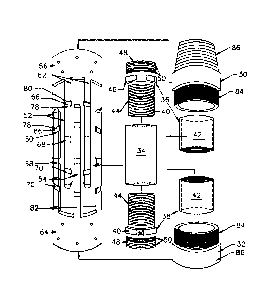
Figure 5 is an exploded perspective view of the various inner components
of the tubing assembly prior to assembly of the inner components and injection
of the
outer jacket of vibration damping material about the inner components;
Figure 6 is a perspective view of the various inner components of the
tubing assembly subsequent to assembly of the inner components but prior to
injection
of the outer jacket of vibration damping material about the inner components.
In the drawings like characters of reference indicate corresponding parts
in the different figures.
DETAILED DESCRIPTION
Referring to the accompanying figures, there is illustrated a vibration
damping tubing assembly generally indicated by reference numeral 10. The
tubing
assembly 10 is intended to be connected in series between two piping sections
coupled
at opposing ends of the tubing assembly such that fluids conveyed by the
piping
sections are conveyed longitudinally through the tubing assembly between the
piping
sections, while isolating vibrations between the piping sections such that
vibrations are
substantially prevented from being communicated from one piping section to the
other.
In a preferred embodiment, the tubing assembly 10 is connected in series
with a tubing string 12 of the type used in producing hydrocarbons from a
wellbore 14.
The wellbore is typically provided with an outer casing 16 lining the casing
with
perforations therein which communicate with a surrounding hydrocarbon
formation in
the ground. The tubing string is typically assembled from a plurality of pipe
sections
which are connected in series to extend in a longitudinal direction through
the casing
and the wellbore. The tubing string is typically suspended from a wellhead 18
at the
surface and defines a production passage communicating therethrough from the
bottom end of the tubing string to the wellhead for conveying produced
hydrocarbon
Date Recue/Date Received 2021-02-01
9
fluids upwardly therethrough.
In the illustrated example, a progressive cavity pump 20 is supported at
the bottom end of the tubing string and includes a rotor 22 rotatably
supported within a
stator 24. Rotation of the rotor within the stator causes cavities between the
rotor and
the stator to progress upwardly for pumping fluid upwardly through the
production
passage in the tubing string when the rotor is rotated. A rod string 26
extends through
the production passage 27 of the tubing string between a drive 28 supported at
the
wellhead and the pump 20 at the bottom of the tubing string. The drive 28 is
used for
driving rotation of the rod string and rotor 22 coupled at the bottom ends
thereof relative
to the stator 24 supported at the bottom end of the tubing string resulting in
a torque
being applied to the stator by the rotor as the rotor is rotated so as to
torque the bottom
end of the tubing string relative to the wellhead. The tubing string thus
resist this torque
applied by the pump in addition to carrying the axial load of the pump and
tubing string
suspended from the wellhead within the wellbore.
The tubing assembly 10 is connected in series between pipe sections of
the tubing string using a first mounting collar 30 and a second mounting
collar 32
supported at opposing first and second ends of the assembly respectively. The
first and
second mounting collars are adapted for connection to the pipe sections,
typically using
conventional male and female threaded connections commonly employed for
joining
pipe sections of a tubing string together. The tubing assembly 10 includes a
fluid
passage 33 communicating longitudinally therethrough between the opposing
mounting
collars such that the fluid passage is connected in series with the production
passage
of the tubing string for conveying fluid therethrough as fluid is pumped
upwardly through
the tubing string.
In some instances, the tubing assembly 10 can be mounted in series with
Date Recue/Date Received 2021-02-01
10
the tubing string in close proximity to the wellhead at the top end of the
tubing string.
Alternatively, the tubing assembly 10 may be mounted in proximity to the pump
at the
bottom end of the tubing string. In yet further arrangements, the tubing
assembly 10
may be mounted in series with the tubing string at an intermediate location
spaced from
both the top and bottom ends of the tubing string. All three locations are
represented in
Figure 1. It may also be desirable in some instances to supported the tubing
assembly
at multiple locations along the tubing string at the same time.
In each instance the tubing assembly 10 provides a gap of resilient,
vibration damping material connected in series between spaced apart rigid
components
of the tubing assembly and the pipe sections above and below the resilient gap
such
that the vibration damping material of the tubing assembly serves to isolate
transmission of vibrations longitudinally therethrough between the pipe
sections
connected at opposing ends of the assembly. When connected in series with a
production tubing string as described above, the tubing assembly 10 serves to
limit
transmission of vibrations from the pump upwardly through the tubing string
while still
being configured to resist any torque applied between opposing ends of the
tubing
assembly and to carry axial loads either under compression or tension between
opposing ends of the tubing assembly as described in further detail below.
The tubing assembly 10 generally includes an inner tubing member 34
comprised of a sleeve of resilient material having a generally cylindrical
inner surface
and a generally cylindrical outer surface with a passage extending
longitudinally
therethrough so that a portion of the inner surface defines part of the
boundary of the
fluid passage of the overall assembly. The sleeve may be formed of a composite
resilient material such as rubber with embedded fiber or strand material
therein so as
to remain resilient while having some strength to contain high-pressure fluids
therein
Date Recue/Date Received 2021-02-01
11
without rupturing the resilient rubber material.
The assembly further includes a first end connector 36 and a second end
connector 38 formed of rigid material, for example metal such as stainless
steel,
mechanically coupled to opposing ends of the inner tubing member 34. Each of
the end
connectors includes an inner member 40 received inside a respective end
portion of
the tubing member and an outer member 42 extending about a respective end
portion
of the outer surface of the tubing member.
More particularly the inner member 40 includes an inner sleeve 44 having
a generally cylindrical outer surface which is ribbed, textured or otherwise
formed with
annular catches thereon so as to mate with the inner surface of the inner
tubing member
34 by interference fit to grip the inner surface relative to the end
connector. The inner
member further includes an integral collar 46 which is enlarged in outer
diameter
relative to the inner sleeve 44 forming a shoulder that abuts the end of the
inner tubing
member 34 in a mounted position. The outer circumference of the integral
collar may
be polygonal in shape to enable gripping with a suitable tool to torque the
end connector
if required. The inner member further includes an end portion 48 extending
axially
outward from the integral collar 46 which is generally cylindrical in shape,
having an
outer diameter which is reduced relative to the collar 46. The inner sleeve
44, the
integral collar 46 and the end portion 48 of each inner member are connected
in series
with a continuous inner diameter throughout in which the cylindrical inner
surface of the
inner member forms part of the boundary of the resulting fluid passage
communicating
through the tubing string. The end portion 48 of the inner member further
includes an
annular groove 50 extending about the circumference thereof for connection to
additional components of the assembly as described in further detail below.
Additional
annular grooves 51 receive 0-rings therein for sealing against adjacent
components.
Date Recue/Date Received 2021-02-01
12
The outer member 42 of each end connector 36 or 38 is an outer sleeve
having a length in the axial direction which is approximately equal to the
inner sleeve
44 of the inner member but has an interior diameter which closely fits with
the outer
diameter of the tubing member. The inner diameter of the outer sleeve is
slightly
undersized relative to the outer diameter of the tubing member however to
apply some
radial constriction or compression to the end portion of the inner tubing
member 34
received therein so that the outer member 42 assists in clamping the end
portion of the
inner tubing member 34 against the textured outer surface of the inner sleeve
44 of the
inner member 40. In this manner each end connector 36 or 38 radially clamps a
respective end portion of the inner tubing member 34 therein to mechanically
couple
the rigid material of the first and second end connectors 36 and 38 to
opposing ends of
the resilient inner tubing member 34.
The inner ends of both end connectors remain mounted with an axial gap
in the longitudinal direction therebetween when the corresponding integral
collars 46 of
the end connectors are abutted at opposing ends of the inner tubing member 34
to
maintain a resilient gap between the rigid components of the first and second
end
connectors in the assembled configuration of the assembly 10.
The assembly 10 further includes a plurality of first connecting portions
52 and a plurality of second connecting portions 54 which are supported on the
first and
second end connectors 36 and 38 respectively.
More particularly, all of the first connecting portions 52 are commonly
supported on a first collar portion 56 in the form of a rigid collar having an
inner end
portion 58 with an inner diameter that mates with and closely receives the
outer
diameter of the end portion 48 of the respective first end connector 36
therein. The 0-
rings within the grooves 51 provide a pressure containing sealing interface
between the
Date Recue/Date Received 2021-02-01
13
first end connector 36 and the first collar portion 56. The first collar
portion 56 also
includes an inner flange 60 in which the inner diameter is stepped inwardly
relative to
the inner end portion 58 to define a shoulder in abutment with the outer end
of the first
end connector 36.
Mounting apertures are provided within the inner end portion 58 of the
first collar portion 56 for receiving radially oriented connecting pins
mounted therein for
alignment with the annular groove 50 in the end portion 48 of the first end
connector 36
received therein to axially fix the first collar portion 56 relative to the
first end connector
36. The first collar portion 56 further includes an outer end portion 62 in
which the inner
diameter is enlarged relative to the inner flange 60 to define an additional
shoulder
which faces axially outward for abutment with the inner end of the first
mounting collar
30 received within the outer end portion of the first collar portion 56. The
outer end
portion may have internal threading thereon to form a threaded connection with
a
corresponding portion of the first mounting collar.
The second connecting portions 54 are similarly supported on a second
collar portion 64 which is substantially identical to the first collar portion
56. More
particularly the second collar portion 64 includes (i) an inner end portion 58
that mates
with the end portion of the second end connector 38 with 0-rings in grooves 51
and
pins received in the annular groove 50, (ii) an inner flange 60 that abuts the
end of the
second end connector 38, and (iii) an outer end portion 62 which is internally
threaded
for connection to a corresponding portion of the second mounting collar 32 as
described
above with regard to the first collar portion 56.
The first connecting portions 52 comprise elongate fingers which are
elongate and extend in the longitudinal direction from the inner end of the
first collar
portion 56 to span most of the axial distance to the other second collar
portion 64;
Date Recue/Date Received 2021-02-01
14
however an axial gap is maintained between the free end of each first
connecting
portion 52 and the second collar portion 64. The first connecting portions are
circumferentially spaced apart from one another such that the gap between any
two
adjacent first connecting portions is greater than the overall width in the
circumferential
direction of each finger. The outer surface of each first connecting portion
forms part of
a generally cylindrical boundary of the first connecting portions collectively
joined to the
first collar portion 56. More particularly the outer surfaces of the first
connecting portion
52 are substantially flush with the outer diameter of the first collar portion
56.
The second connecting portions 54 are substantially identical to the first
.. connecting portions so as to comprise elongate fingers which extend in the
longitudinal
direction from the inner end of the second collar portion 64 to span most of
the axial
distance to the other first collar portion 56 while maintaining an axial gap
between the
free end of each second connecting portion 54 and the first collar portion 56.
Each
second connecting portion 54 is received within the gap in the circumferential
direction
between an adjacent pair of the first connecting portions 52 so as to define
an
alternating sequence of first and second connecting portions about the full
circumference of the tubing assembly. The width in the circumferential
direction of each
connecting portion is consistent, as is the gap in the circumferential
direction between
each first connecting portion and each of the adjacent second connecting
portions on
.. either side thereof.
The outer surfaces of all of the connecting portions collectively define an
outer cylindrical boundary which is substantially flush with the outer
cylindrical surfaces
of both first and second collar portions. The inner surfaces of the connecting
portions
are all generally concave in the circumferential direction so that the inner
surfaces
collectively define an inner cylindrical boundary having an inner diameter
which closely
Date Recue/Date Received 2021-02-01
15
matches the outer diameter of the outer members 42.
Each of the first connecting portions 52 and the second connecting
portions 54 includes a first outer groove 66 formed therein at a location
which is closer
to the first collar portion 56 than the second collar portion 64. Each first
outer groove 66
extends circumferentially across the full width of the finger while being
recessed relative
to the outer surface of the finger in the radial direction to define a groove
which is open
radially to the exterior. All of the first outer grooves 66 of the first
connecting portion 52
and the second connecting portion 64 are aligned with one another to define a
common
circumferential channel extending about the full circumference of the
collective first and
second connecting portions.
Each of the first connecting portions 52 and the second connecting
portions 54 also includes a second outer grooves 68 formed therein at a
location which
is closer to the second collar portion 54 than the first collar portion 56.
Each second
outer groove 68 extends circumferentially across the full width of the finger
while being
recessed relative to the outer surface of the finger in the radial direction
to define a
groove which is open radially to the exterior. All of the second outer grooves
68 of the
first connecting portions 52 and the second connecting portions 54 are aligned
with one
another to define a second common circumferential channel extending about the
full
circumference of the collective first and second connecting portions at a
location axially
spaced from the first common circumferential channel.
Each of the first connecting portions 52 and the second connecting
portions 54 also includes an inner groove 70 formed therein at a location
which is
intermediate and spaced inwardly from both the first and second outer grooves.
Each
inner groove 70 extends circumferentially across the full width of the finger
while being
.. recessed relative to the inner surface of the finger in the radial
direction to define a
Date Recue/Date Received 2021-02-01
16
groove which is open radially to the interior. All of the inner grooves 70 of
the first
connecting portions 52 and the second connecting portions 54 are aligned with
one
another to define a third common circumferential channel extending about the
full
circumference of the collective first and second connecting portions.
One or more outer rings 72 are provided within the first common
circumferential channel defined by the first outer grooves 66 collectively.
Each outer
ring 72 has an inner diameter which is close to the recessed diameter of the
first outer
grooves 66 and an outer diameter which is close to the outer diameter of the
outer
cylindrical boundary defined by the outer surfaces of the first and second
connecting
portions.
One or more outer rings 72 are also provided within the second common
circumferential channel in the same manner as they are provided within the
first
common circumferential channel described above. The overall thickness of the
one or
more rings in each instance in the axial direction and in the radial direction
is slightly
undersized relative to the dimensions of the channel receiving the one or more
rings
therein to provide some gaps between the rigid components of the assembly. The
outer
rings 72 are formed of rigid metal in each instance. Each of the outer rings
may be a
split ring for ease of mounting onto the assembly.
One or more inner rings 74 are provided within the third common
circumferential channel defined by the inner grooves 70 collectively. Each
inner ring 74
has an inner diameter closely matching the inner diameter of the
circumferential
boundary defined by the inner surfaces of the first and second connecting
portions
collectively. The outer diameter of the inner rings 74 is close to the
recessed diameter
of the inner grooves. The inner rings are similarly formed of rigid metal and
may
comprise a split ring for ease of mounting onto the assembly. The overall
thickness of
Date Recue/Date Received 2021-02-01
17
the inner rings in the axial direction and in the radial direction is also
slightly undersized
relative to the dimensions of the channels receiving the rings therein to
provide some
gaps between rigid components of the assembly.
All of the above noted components, with the exception of the inner tubing
.. member 34, are formed of a rigid material, for example a metal such as
stainless steel.
Once the rigid components described above have all been mounted in relation to
one
another, an outer jacket 76 of vibration damping material is applied to the
exterior of
the assembly by injection moulding such that the resulting outer diameter of
the jacket
76 is substantially continuous along the length of the assembly between the
first and
second mounting collars at opposing ends. The outer jacket 76 is molded to the
outer
surface of the inner tubing member 34 which defines an inner boundary of the
outer
jacket 76. More particularly, the vibration damping material of the outer
jacket fills all
voids between the rigid material supported externally of the inner tubing
member 34.
Portions of the vibration damping material of the outer jacket and of the
inner tubing member collectively fully surround and embed all of the
connecting portions
52 and 54 therein as well as the inner and outer rings 74 and 72 described
above such
that some of the vibration damping material isolates each rigid component from
adjacent rigid components of the assembly. The various rigid components,
including
the first connecting portion 62 and the second connecting portions 54, and the
inner
.. and outer rings supported therebetween, are all maintained in a slightly
spaced relation
relative to one another by a layer of the vibration damping material
therebetween so
that various portions of the vibration damping material are clamped under
compression
between opposing load bearing surfaces acting in one or both circumferential
directions
and/or one or both axial directions depending upon the loading configuration
of the
tubing assembly 10.
Date Recue/Date Received 2021-02-01
18
Each first connecting portion 52 defines a plurality of first load bearing
surfaces formed thereon. The first load bearing surfaces include (i) first
shoulder
surfaces 78 formed at the boundaries of the inner and outer grooves which lie
perpendicular to the longitudinal direction and face towards the first collar
portion or first
mounting collar 30, (ii) second shoulder surfaces 80 formed at the boundaries
of the
inner and outer grooves which lie perpendicular to the longitudinal direction
and face
toward the second collar portion or second mounting collar 32, and (iii) side
surfaces
82 extending the full length of each first connecting portion at
circumferentially opposing
sides thereof in which the side surfaces are oriented generally in the
longitudinal
direction and face perpendicularly to a circumferential direction of the
tubing assembly.
Similarly, each second connecting portion 54 defines a plurality of second
load bearing surfaces formed thereon. The second load bearing surfaces include
(i) first
shoulder surfaces 78 formed at the boundaries of the inner and outer grooves
which lie
perpendicular to the longitudinal direction and faced towards the second
collar portion
or second mounting collar 32, (ii) second shoulder surfaces 80 formed at the
boundaries
of the inner and outer grooves which lie perpendicular to the longitudinal
direction and
face toward the first collar portion or first mounting collar 30, and (iii)
side surfaces 82
extending the full length of each second connecting portion at
circumferentially
opposing sides thereof in which the side surfaces are oriented generally in
the
longitudinal direction and face perpendicularly to a circumferential direction
of the tubing
assembly.
In this manner, when the tubing assembly undergoes axial tension acting
to pull the first and second mounting collars apart from one another, a
portion of the
vibration damping material against the first shoulder surfaces 78 of both
connecting
portions and which is between the first shoulder surfaces and opposing
surfaces of the
Date Recue/Date Received 2021-02-01
19
inner and outer rings received therebetween, will be under compression between
the
rigid load bearing surfaces which face one another to provide sufficient
strength to
support loads under axial tension while maintaining a gap of the vibration
damping
material between any rigid components.
Similarly, when the tubing assembly undergoes axial compression acting
to push the first and second mounting collars towards one another, a portion
of the
vibration damping material against the second shoulder surfaces 80 of both
connecting
portions and opposing surfaces of the inner and outer rings received
therebetween will
be under compression between the rigid load bearing surfaces which face one
another
to provide sufficient strength to support loads under axial compression while
maintaining a gap of the vibration damping material between any rigid
components.
Furthermore, when the tubing assembly undergoes a torque applied in
either direction between the first and second mounting collars, a portion of
the vibration
damping material against one of the side surfaces 82 of all of the first and
second
connecting portions will undergo some compression between one side surface of
each
connecting portion and the opposing side surface of an adjacent connecting
portion that
it faces to support loads therebetween, while maintaining a gap of the
vibration damping
material between any rigid components.
Each of the first and second first mounting collars 30 and 32 includes an
inner end portion 84 having an inner diameter which fits within the
corresponding outer
end portion of the first or second collar portion 56 or 64 respectively. The
inner
diameters of the mounting collars closely match the inner diameters of the
first and
second end connectors 36 and 38 to define part of the boundary of the fluid
passage
extending through the assembly. Once the inner end portion 84 of the mounting
collar
is received within the respective collar portion 56 or 64, connection may be
maintained
Date Recue/Date Received 2021-02-01
20
by a threaded connection, or the use of radially oriented pins extending
through the
components.
Each of the first and second mounting collars 30 and 32 also includes an
outer end portion 86 which serves to connect the mounting collar to the
adjacent pipe
section of the tubing string. In the illustrated embodiment the outer end
portion 86 of
the first mounting collar 30 comprises an externally threaded male connector
for forming
a mating connection with the female connector of an adjacent tubing section.
Furthermore, in the illustrated embodiment, the outer end portion 86 of the
second
mounting collar 32 comprises an internally threaded female connector for
forming a
mating connection with the male connector of an adjacent tubing section of the
tubing
string.
As described herein, rigid material is understood to comprise a material
that substantially maintains its shape under considerable load, for example
structural
metal.
Resilient material is understood herein to be much more flexible and
elastic than the rigid material, for example rubber, or a composite material
of elastic
material with embedded fibres having greater tensile strength to increase the
strength
of the rubber. The vibration damping material is a suitable resilient material
capable of
absorbing some of the vibratory forces from the adjacent rigid components to
prevent
vibrations from transferring from one rigid component to another.
Since various modifications can be made in my invention as herein above
described, and many apparently widely different embodiments of same made, it
is
intended that all matter contained in the accompanying specification shall be
interpreted
as illustrative only and not in a limiting sense.
Date Recue/Date Received 2021-02-01