Note : Les descriptions sont présentées dans la langue officielle dans laquelle elles ont été soumises.
CA 03107690 2021-01-25
WO 2020/028613
PCT/US2019/044582
CURVED PREFORM AND
METHOD OF MAKING THEREOF
Cross-Reference to Related Application
This application claims the benefit of priority of U.S. Provisional
Application Serial No.
62/713,206 filed August 1, 2018, which is hereby incorporated by reference in
its entirety.
BACKGROUND
1. Field
lci This disclosure relates to woven preforms and particularly relates to
woven preforms used in
reinforced composite materials. More particularly, the present invention
relates to woven
preforms that are curved with continuous fiber reinforcement.
2. Related Art
The use of reinforced composite materials to produce structural components is
now widespread,
particularly in applications where their desirable characteristics of light
weight, high strength,
toughness, thermal resistance, and ability to being formed and shaped can be
used to great
advantage. Such components are used, for example, in aeronautical, aerospace,
satellite, high
performance recreational products, and other applications.
Typically, such components consist of reinforcement materials embedded in
matrix materials.
The reinforcement component may be made from materials such as glass, carbon,
ceramic,
aramid, polyester and/or other materials that exhibit desired physical,
thermal, chemical and/or
other properties, chief among which is strength against stress failure.
Through the use of such reinforcement materials, which ultimately become a
constituent
element of the completed component, the desirable characteristics of the
reinforcement
materials, such as high strength, are imparted to the completed composite
component. The
typical constituent reinforcement materials may be woven, knitted or otherwise
oriented into
desired configurations and shapes for reinforcement preforms. Usually
particular attention is
paid to ensure the optimum utilization of the properties for which the
constituent reinforcing
materials have been selected.
1
CA 03107690 2021-01-25
WO 2020/028613
PCT/US2019/044582
After the desired reinforcement preform has been constructed, matrix material
may be
introduced into the preform so the reinforcement preform becomes encased in
the matrix
material and matrix material fills the interstitial areas between the
constituent elements of the
reinforcement preform. The reinforcement preform combined with matrix material
can form
desired finished components or to produce working stock for the ultimate
production of finished
components.
The matrix material may be any of a wide variety of materials, such as epoxy,
polyester, vinyl-
ester, ceramic, carbon and/or other materials, which also exhibit desired
physical, thermal,
lci chemical, and/or other properties. The materials chosen for use as the
matrix may or may not
be the same as that of the reinforcement preform and may or may not have
comparable
physical, chemical, thermal and/or other properties. Typically, however, they
will not be of the
same materials or have comparable physical, chemical, thermal, or other
properties, because a
usual objective sought in using composites in the first place is to achieve a
combination of
characteristics in the finished product that is not attainable through the use
of one constituent
material alone. So combined, the reinforcement preform and the matrix material
may then be
cured and stabilized in the same operation by thermosetting or other known
methods, and then
subjected to other operations toward producing the desired component. It is
significant to note
at this point that after being so cured, the then solidified masses of the
matrix material normally
are very strongly adhered to the reinforcing material (e.g., the reinforcement
preform).
A common method of producing a woven preform is to weave a two dimensional
("2D") structure
and fold it into a three dimensional ("3D") shape. A benefit of folded
preforms is the strength of
the joint between the panel to be reinforced and the reinforcing panel. As
they are woven
together, the panels share reinforcing material and in the final composite,
matrix material,
creating a unitary construction. The juncture between the integrally woven
reinforcement flange
or leg and the parent material or base is no longer the weak link, relying
solely upon the
strength of the adhesive for the strength of the joint, as in the prior-art
reinforcements. Instead,
the fibers of the preform integrally weave the legs and the base together.
Frequently, however, complex shapes, such as curves, require reinforcement.
Folded T- or Pi-
shaped and other preform reinforcements having a flange base with one or more
upstanding
legs require darting of the legs in order to accommodate a curved surface. As
the flange
2
CA 03107690 2021-01-25
WO 2020/028613
PCT/US2019/044582
material of a folded preform assumes a curved shape, the length of the curved
surface
necessarily varies from the inside of the curvature to the outside of the
legs. The arc length of
outside of the curvature, the surface with the larger radius when curved,
increases, while on the
inside of the curvature, the arc length decreases. The legs of typical folded
preforms cannot
change length as required to accommodate a curved surface. To accommodate a
curved
surface, the legs must be darted. That is, the legs must be cut or have
discontinuous fibers in
order to allow the leg to conform to the changed arc length.
Typically, the cut is along the localized radius of curvature, but other, non-
radial cuts may also
lci be used to accommodate the change in length. To allow for the decreased
length on the inside
of a curved preform, the leg is cut and the cut edges allowed to overlap, or
the excess material
is removed. Similarly, to accommodate the increased length on the outside of
the curvature, the
leg is cut, resulting in a triangular gap between cut edges of the leg. In
either configuration, the
darting breaks the continuity of the reinforcing fibers in each leg. Darting
the legs of a 3D T- or
Pi-preform can degrade the load carrying capabilities of the preform, because
darting involved
cutting the fibers that provide the primary load path around the curve.
SUMMARY OF THE DISCLOSURE
A method of forming a curved preform includes applying at least one set of
mating clamps to
fibers of a preform fabric advancing from a loom, the at least one pair of
mating clamps
capturing at least a portion of the preform fabric there between. The at least
one set of clamps
having a geometry to increase a length of fibers by pulling at least some of
the fibers advancing
from the loom. The preform fabric is shaped into a curve. And the fibers are
continuous along a
length of the fabric. In some embodiments, the length of the fibers is greater
at an outside of the
curve than at an inside of the curve. In other embodiments, the length of the
fibers is shorter at
an outside of the curve than at an inside of the curve.
In one embodiment, each set of mating clamps is a pair of clamps. In another
embodiment,
each set of mating clamps is at least three clamps. The mating clamps may
include an upper
clamp portion and a lower clamp portion. In certain embodiments, the lower
clamp portion
comprises at least two mating parts.
3
CA 03107690 2021-01-25
WO 2020/028613
PCT/US2019/044582
In certain embodiments, there are at least two sets of mating clamps applied
to the preform
fabric. A force is applied to each set of mating clamps to compress the
preform fabric there
between. Adjacent mating clamps may be mated to one another. The two or more
sets of
mating clamps can be disposed in separate locations of the preform fabric to
increase the length
of the fibers in each of the separate locations but not in other locations.
In other embodiments, described herein are curved woven preforms, for example,
a curved
woven preform comprising a plurality of weft fibers and a plurality of warp
fibers interwoven with
the plurality of weft fibers to form a base of the preform, wherein the base
of the preform is
to curved with the warp fibers continuous across the length of the preform
and some of the warp
fibers are longer than other warp fibers.
In certain embodiments, the curvature of the woven preform is convex, the
length of the warp
fibers being greater towards an outside of the curve of the preform than
towards an inside of the
curve of the preform. In a further embodiment, the preform comprises at least
one leg integrally
woven with the base and curved along a length of the base, wherein warp fibers
forming the at
least one leg are greater towards an outside curve of the at least one leg
than towards an inside
curve of the at least one leg.
.. In other embodiments, the curvature of the woven preform is concave, the
length of the warp
fibers being shorter towards an outside of the curve of the preform than
towards an inside of the
curve of the preform. In a further embodiment, the preform comprises at least
one leg integrally
woven with the base and curved along a length of the base, wherein warp fibers
forming the at
least one leg are shorter towards an outside curve of the at least one leg
than towards an inside
curve of the at least one leg.
The instant invention also relates to clamps, such as an upper clamp mateable
with a lower
clamp, wherein the upper clamp has a complementary shape to mate with the
lower clamp and
configured to receive a fabric therebetween. In another embodiment, the
invention relates to an
.. upper clamp having a blade portion and a lower clamp separable and mateable
with the upper
portion, the lower clamp having a lower clamp first part and a lower clamp
second part, wherein
the lower clamp first and second parts have a gap therebetween such that the
blade portion of
the upper clamp enters into the gap when the upper and lower clamps are mated
together.
4
CA 03107690 2021-01-25
WO 2020/028613
PCT/US2019/044582
In yet other embodiments, the invention relates to a shaping clamp system
comprising two or
more clamps, each clamp having an upper clamp portion and a lower clamp
portion and an
integral connecting portion, wherein the two or more clamps are connectable to
one another by
the connecting portion and configured to receive a fabric therebetween. In
certain embodiments,
the invention relates to a shaping clamp system comprising two or more clamps,
each clamp
having an upper clamp portion with a blade portion and a lower clamp portion,
each clamp
including an integral connecting portion, wherein each lower clamp is
separable and mateable
with a respective upper clamp, the lower clamp having a lower clamp first part
and a lower
lci clamp second part with a gap therebetween to receive the blade portion
when the upper clamp
and lower clamp are mated together, wherein the two or more clamps are
connectable to one
another by the connecting portion and configured to receive a fabric
therebetween.
BRIEF DESCRIPTION OF THE DRAWINGS
The accompanying drawings, which are included to provide a further
understanding of the
invention, are incorporated in and constitute a part of this specification.
The drawings presented
herein illustrate different embodiments of the invention and together with the
description serve
to explain the principles of the invention. In the drawings:
FIGS. 1A-1C illustrate an example of a T-preform as woven and folded into a
final shape.
FIGS. 2A-2B illustrate an example of a curved T-preform.
FIG. 3 illustrates an example of a clamp geometry to increase the length of
fibers in the tip of a
preform as compared with the root of the preform.
FIGS. 4A-4B illustrate a fabric having lengthened fibers between the fabric
width edges.
FIG. 5 illustrates application of pairs of mating clamps to a preform fabric
to increase the length
of fibers.
FIG. 6 illustrates another embodiment of a clamp for lengthening fibers of a
preform fabric.
FIGS. 7A-7B illustrate application of the clamp of Figure. 6.
FIGS. 8A-8E illustrate examples of preforms having complex geometries that may
be formed.
FIG. 9 illustrates an example of an 0 preform that may be formed.
FIG. 10 illustrates an example of a clamp design according to the instant
invention.
5
CA 03107690 2021-01-25
WO 2020/028613
PCT/US2019/044582
DETAILED DESCRIPTION
Terms "comprising" and "comprises" in this disclosure can mean "including" and
"includes" or
can have the meaning commonly given to the term "comprising" or "comprises" in
U.S. Patent
Law. Terms "consisting essentially of" or "consists essentially of" if used in
the claims have the
meaning ascribed to them in U.S. Patent Law. Other aspects of the invention
are described in
or are obvious from (and within the ambit of the invention) the following
disclosure.
The terms "threads", "fibers", "tows", and "yarns" are used interchangeably in
the following
description. "Threads", "fibers", "tows", and "yarns" as used herein can refer
to monofilaments,
multifilament yarns, twisted yarns, multifilament tows, textured yarns,
braided tows, coated
yarns, bicomponent yarns, as well as yarns made from stretch broken fibers of
any materials
known to those ordinarily skilled in the art. Yarns can be made of carbon,
nylon, rayon,
fiberglass, cotton, ceramic, aramid, polyester, metal, polyethylene glass,
and/or other materials
that exhibit desired physical, thermal, chemical or other properties.
The term 'folded" is broadly used herein to mean "forming," which includes
unfolding, bending,
and other such terms for manipulating the shape of a fabric.
For a better understanding of the invention, its advantages and objects
attained by its uses,
reference is made to the accompanying descriptive matter in which non-limiting
embodiments of
the invention are illustrated in the accompanying drawings and in which
corresponding
components are identified by the same reference numerals.
Disclosed is a method for creating curved preforms of continuous fiber on a
conventional
straight loom take-up. Machine woven fabrics are created using a loom that
includes a weaving
mechanism coupled with a method for advancing and collecting the finished
fabric. "Straight
take-up" means the fabric is collected in the warp or machine direction (MD)
in short lengths
adapted for weaving discrete preforms.
Typical shapes woven with the straight take-up include Pi-shaped or T-shaped
preforms used
as structural reinforcement members in a variety of applications. These shapes
being made of
continuous fiber in both the warp and weft directions can be difficult to form
into a geometry or
curved shape in the warp or take-up direction.
6
CA 03107690 2021-01-25
WO 2020/028613
PCT/US2019/044582
As an example, FIGS. 1A-1C illustrate a simplified version of forming a 1-
preform from 1-
preform fabric 100. Warp and weft fibers are interwoven in a loom 106,
illustrated by the dotted
lines. As the 1-preform fabric is woven, the fabric advances in the direction
A towards a take-up
roll (not shown) for receiving the completed fabric. The portion of the fabric
that has already
been formed but not yet rolled up on the take-up roll is called the "fell"
108.
The 1-preform fabric includes base portions 102a, 102b and leg portion 104. A
root 110 of leg
portion 104 may be interwoven with base portions 102a, 102b. Base portions
102a, 102b are
lci not interwoven at their intersection 114 and the remainder of the leg
portion 104 is not
interwoven with the base portions other than at their intersection 110. The 1-
preform fabric 100
is woven and advances toward and onto the take-up roll. Once a desired length
L of the 1-
preform fabric is woven, the fabric may be removed from the loom. Base
portions 102a, 102b,
and leg portion 104 can be folded to form 1-preform 120.
Other preform shapes including, but not limited to, Pi, H, 0, and I can be
woven and folded into
their final form as known to those of ordinary skill. Any of the preforms can
be impregnated with
a matrix material to form a composite.
FIG. 2A illustrates an example of a curved preform. For purposes of
discussion, the curve
illustrated in FIG. 2A and other figures is referred to as being "convex."
Accordingly, the
example is of a convex T-shaped preform but other preform shapes including,
but not limited to,
Pi, H, 0 and I are contemplated. Similar to the fabric in FIG. 1, the 1-
preform fabric includes
base portions 202a, 202b and leg portion 204. Base portions 202a, 202b and leg
portion 204
are folded to form 1-preform 220.
Base portions 202a, 202b and leg portion 204 are woven from warp fibers 222.
As shown in
FIG. 2B, the length L2 of warp fibers 222 in the warp direction are shorter
towards the inside or
root 226 of the curved 1-preform than towards the outside or tip 224 of the
curved 1-preform.
Accordingly, in order to curve a preform woven as in FIG. 1, the fiber length
in the warp direction
must be greater at the tip of the curved preform than at the root of the
curved preform.
7
CA 03107690 2021-01-25
WO 2020/028613
PCT/US2019/044582
While curved preforms are known in the art, these prior-art preforms required
cutting of fibers or
making the length from discontinuous short fibers, such as stretch broken
fibers, to enable the
preform to be stretched or curved to provide additional length of the preform
towards the outside
of the curvature as compared with towards the inside of the curvature. There
is a weakening, a
.. loss of strength, of the preform due to the cutting and/or discontinuity of
the fibers in providing
the additional length.
In contrast, the present disclosure provides preforms and a process for
weaving preforms with
additional length of fibers so the finished structure can be curved and have
continuous fiber
reinforcement in the direction of the curvature. Continuous fibers provide
greater preform
strength than discontinuous fibers. "Continuous fibers" are fibers having no
breaks along the
entire length of the fabric. In embodiments of the present disclosure, the
fibers of the fabric are
continuous in the direction of curvature of the preform and can have varying
lengths across the
width of the fabric. The varying lengths across the preform fabric width
enable forming a curved
portion in the length of the fabric without cutting the fibers or having the
fibers discontinuous to
form the curved portion.
For the purposes of this disclosure, the direction of curvature of the preform
will be assumed to
be along the warp or machine direction (MD) of the fabric. However, it is
contemplated that the
disclosed technique may be used to effect curvature of the fabric in the weft
or cross-machine
direction (CD) alone or in combination with the warp direction.
To create this curvature, according to an embodiment of the present
disclosure, the length of
the fibers in upright leg 204 is made longer towards the outside tip 224 of
the preform upright
leg than the inside root 226 of the preform leg by applying one or more damps
to the fabric as
the fabric comes off of the loom. The clamps may be applied in the fell of the
cloth. The shape
of the clamps is designed to draw additional fiber length into the preform to
accommodate an
increase in length of the fibers to enable curvature of the preform when the
preform is formed to
the desired shape.
In embodiments of the instant invention, each clamp incrementally increases
the length of the
warp fibers coming off the loom. In the clamp depicted in FIG. 10, for
example, to accommodate
the longer radius of the outside of a preform curvature (Ro) versus the
shorter radius of the
8
CA 03107690 2021-01-25
WO 2020/028613
PCT/US2019/044582
inside of the curvature (Ri), the clamp is designed such that as each clamp
segment is applied
to the warp fibers coming off the loom, the resulting length of the warp fiber
on the inside (Wi) of
the preform curvature is shorter than the warp fiber on the outside (Wo) of
the preform
curvature, The resulting difference in length of the fibers, Wo and Wi, is
shown.
It is contemplated that the preform fabric can be made concave as illustrated
in the examples of
FIGS. 8C, 8D, and 8E. In embodiments of concave preform fabrics such as FIG.
8D having
base portions 802a, 802b, the lengths of the warp fibers forming the upright
legs 804 would be
opposite to that of the convex preform fabric. That is, the length of the
fibers in upright legs 804
ro are shorter towards the outside tip 824 of the preform upright leg than
towards the inside root
826 of the preform leg. Those of ordinary skill in the art will appreciate the
general
understanding that the geometry of the final preform shape determines the
necessary length of
fibers across the preform length to enable forming the required curvature.
Altering of the length
of the fibers so that they are continuous across the length of the fabric
distinguishes forming
preform fabrics according to the present disclosure from the discontinuous
fibers across the
length of prior-art curved preforms.
FIG. 3 illustrates an example of a clamp element 300. The clamp 300 is applied
to the preform
fabric exiting the loom. The clamp is oriented on the preform fabric so that a
clamp root end
326 is applied to the root end of an upright leg and a clamp tip end 324 is
applied to the tip end
of the upright leg. For a convex curvature as in FIGS.1 and 2, the clamp root
end is straight,
which does not increase the length of the fibers because the root end of the T-
preform upright
leg has the shortest length of fibers in the curved preform. The clamp tip end
has a geometry or
shape to lengthen the preform fabric fibers of a convex curvature. That is,
the geometry of the
clamp causes added fiber take-up length to be drawn from the loom to traverse
across towards
the clamp tip end than towards the clamp root end. The geometry is more
pronounced --
causing greater fiber take-up length to be drawn from the loom - at the clamp
tip end because
the tip end of a convex preform with an upright leg(s) has the longest fibers
in the curved
preform. The geometry of the clamp is reduced towards the clamp root end as
the length of the
fibers are shorter towards the root of the curved preform. In this way the
fibers are longest at
the tip of the curved preform fabric upright leg and shortest at the root. Of
course, the geometry
of the clamp is reversed with respect to the upright leg of a preform with
concave curvature.
9
CA 03107690 2021-01-25
WO 2020/028613
PCT/US2019/044582
The damps are typically assembled on the preform fabric in sets. Each set of
damps includes
two or more damps having mating geometries. The damping action of sandwiching
the preform
fabric between the set of damps draws additional fiber take-up length through
the loom. The
damp set geometries are tapered such that the take-up length increases from
the root (inside
curve of the preform) to the tip of an upright leg(s) (outside curve of the
preform) for a preform
with convex curvature (reversed damp geometry for a preform with concave
curvature). The
increase in length of the fibers can enable forming of the preform fabric into
the curved preform
of FIG. 2 with continuous lengths of fibers throughout the curved preform. The
curvature of the
preform is achieved with continuous lengths of fibers and not weakened by
cutting fibers or
.. shortened fibers, such as stretch broken fibers.
The geometry of a damp shown in FIG. 3 is for illustrative purposes only.
Design
considerations will determine the particular geometry selected for the damps.
Moreover, the
geometry of the damps can be varied over the length of a preform to provide
for alternative
contours or curvatures of the preform fabric over the length of the preform.
Figure. 4A illustrates a fabric where the damp geometry has been arranged to
provide a
lengthening of the fibers anywhere along the width of the fabric. That is, the
fibers may be
lengthened between the width edges of the fabric to cause a curvature across
the width of the
fabric, In one embodiment, the damp sets are arranged to cause a lengthening
of the fibers
toward the center of the fabric, in one embodiment, the preform fabric can be
cut in the middle
of the warp direction to create two curved preforms with continuous fiber
along the length of
curvature. As shown in Figure 48, in this embodiment, the curvature is
arranged in the plane of
the preform fabric. It is contemplated that damp geometry could also be made
to cause a
lengthening of fibers in a multilayer fabric. Some of the layers can be folded
into one or more
upstanding legs from the plane or base of the preform fabric that follow the
curvature of the
plane of the preform fabric and shown in FIG. 2.
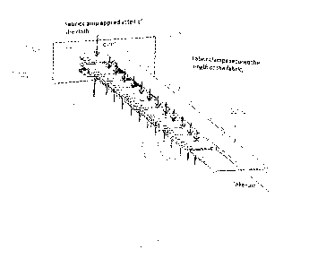
Figure 5 illustrates an embodiment where the set of damps is a pair of mating
damps 502a,
502b assembled on preform fabric 504 as the fabric exits the loom 506. These
damps may be
held in place throughout the weaving process by a force F applied to the
mating damps to press
the preform fabric between the damps and vary the length of continuous fibers
along the length
of the preform. The force holding the damp pairs together may be achieved in
any manner
CA 03107690 2021-01-25
WO 2020/028613
PCT/US2019/044582
known to those of ordinary skill including, but not limited to, screws and
nuts, springs, etc. In
one embodiment, adjacent clamp pairs, such as 508, 510, can be assembled to
one another.
Figure 6 illustrates an embodiment where a set of clamps 600 is arranged to
intersect to
lengthen the fibers when applied to a preform fabric. The set of clamps 600
includes an upper
clamp 602 having a blade portion 608. A lower clamp 610 has portions 604, 606
having a gap
612 therebetween to receive blade portion 608. Lower clamp 610 may be a single
piece or
attached separate pieces. If separate pieces, clamp set 600 may be considered
to have an
upper clamp 602 and lower clamps 604, 606. An advantage of separate pieces for
clamp set
600 is that each of the pieces may be mechanically the same to reduce cost of
manufacturing
and stocking the parts. Also, the gap 612 between lower clamps 604, 606 may be
varied to
accommodate differing preform fabric thicknesses.
Figures 7A-78 illustrate the set of clamps 600 being brought together. In
Figure 7A the upper
clamp 602 is arranged on top of the preform fabric (not shown for clarity) and
lower clamp 610 is
arranged beneath the preform fabric. The upper and lower clamps are separated
by a distance
702 so that blade 608 of the upper clamp does not enter the gap 612 in the
lower clamp.
The blade portion for a convex preform has a geometry to cause a lengthening
of fabric fibers
when applied. In an embodiment, the blade portion is more pronounced or bigger
toward the
center 704 than toward the end 706 of the blade portion. That is, the blade
portion is shaped to
cause the fibers of the preform fabric to be longer to traverse the distance
towards the more
pronounced center of the blade than around the ends of the blade. As discussed
above, the
geometry of the blade portion would be opposite for a concave preform so that
the fibers of the
preform fabric will be shorter to traverse a distance towards a less
pronounced center of the
blade than around the ends of the blade.
A force F is applied to urge the upper and lower clamps together. As shown in
Figure 7B, the
distance 702 is narrowed so blade portion 608 enters into the gap 612 in the
lower clamp.
Distance 702 is adjusted as necessary to enable passage of the preform fabric
around the blade
portion and intersection of the upper and lower clamps. The blade portion 608
causes the fibers
of the preform fabric to be longer to traverse the distance towards the more
pronounced center
of the blade 704 than around the ends of the blade.
11
CA 03107690 2021-01-25
WO 2020/028613
PCT/US2019/044582
While FIG. 2 illustrates an example that results in a fabric with a single
curvature, it is possible
to design a variety of clamp sets to achieve more complex geometries. For
example, an oval
shaped preform can be created by varying the amplitude of the damp curvatures
along the
length of the preform. In FIG. 9, an example of an 0 preform 900 is shown that
was made in
accordance with the instant invention. It is contemplated that damp pairs may
be applied to
some portions of the preform fabric and not to other portions. That is,
additional fiber length
may be pulled from the loom in some areas of the preform fabric and not in
other areas of the
preform fabric. In this way, complex geometries of preforms with curved and
straight portions
.. can be formed. Some examples of such complex shaped preforms are
illustrated in FIG. 8.
Once the required fabric length is woven and the preform fabric is removed
from the loom, any
remaining clamps can be removed and the preform fabric shaped to the final
configuration. In
any of the embodiments, the final configuration can be impregnated with a
matrix material. The
.. matrix material includes epoxy, bismaleimide, polyester, vinyl-ester,
ceramic, carbon, and other
such materials known to those of ordinary skill in the art.
Other embodiments are within the scope of the following claims.
12