Note : Les descriptions sont présentées dans la langue officielle dans laquelle elles ont été soumises.
1
Method for imaging or spectroscopy with a non-linear interferometer
The present invention provides an improvement method for imaging or
spectroscopy with a non-linear interferometer and an improvement apparatus for
imaging or spectroscopy.
Non-linear interferometer allows probing an unknown object, preferably sample,
at
a particular wavelength, while detecting correlated light at the same or a
different
wavelength. In known non-linear interferometry systems, it is crucial to have
an
absolutely correct interferometer setting for perfectly determining the
maximum
constructive and destructive images. To get this, the interferometer must be
adjusted before each measurement. This, for example, can be done by the
measurement of the visibility of the interferometer to find the maximum
constructive and/or destructive interference without the object in the setup.
Due to stability drifts of the interferometer, the stability of the setup
cannot be
guaranteed for long operation times which results in a decrease of the
interference visibility and a decrease of the precision of the measurement.
The
stability drifts can occur among other things due to thermal changes in the
setup,
mechanical and/or thermal instability of the components and even vibrations of
the
underground. For longer operation times in known systems the setup has to be
readjusted to the maximum destructive and/or constructive interference or it
is
necessary to readjust the fringe center.
It is an object of the present invention to provide an improved, more precise
method for imaging or spectroscopy with a non-linear interferometer, also
allowing
longer measurement times and an improved more precise apparatus for imaging
or spectroscopy.
Date Recue/Date Received 2022-11-18
2
According to the present invention, a method for imaging and/or spectroscopy
of
an object is provided.
The method comprises the steps
i) generation of a first signal field Si and a first idler field it, by
pumping a first
non-linear medium with a pump beam, such that the two fields are correlated,
ii) illumination of the object with the first idler ii field, respectively
by transmission
and/or reflection,
iii) generation of a second signal field 52 and a second idler field i2,
- by pumping a spatial separate second non-linear medium with the pump
beam, or
- by pumping the first non-linear medium a second time with the pump beam,
such that the two fields are correlated,
iv) combination of the first ii and second i2 idler fields, such that the two
fields are
indistinguishable, and
combination of the first Si and second S2 signal fields, such that the two
fields
interfere,
v) first measurement of the interfered signal field s12 by a detection means,
vi) one or more additional measurements of the interfered signal field s12 by
the
detection means,
wherein for each additional measurement in step vi) a different phase shift a
is
generated in the setup, and
wherein the first measurement in step v) and the one or more additional
measurements in step vi) are all carried out within the stability time of the
setup,
.. vii) calculation of the phase function (1) out of the measurements from
step v) and
step vi) in order to get an image and/or a spectrum of the object.
The invention further provides an apparatus for imaging and/or spectroscopy.
The apparatus comprises a pump source to generate a pump beam, and
Date Recue/Date Received 2022-11-18
3
a first signal Si and idler ii field generation means pumped by the pump beam,
and
a second signal s2 and idler i2 field generation means pumped by the pump
beam,
wherein the first and the second field generation means are
- two spatial separated nonlinear media pumped by the pump beam, or
- one non-linear medium, pumped by the pump beam a first time to
generate a
first signal Si and idler ii field and pumped a second time to generate a
second signal s2 and idler i2 field, and
an object to be measured which is illuminated, respectively by transmission or
reflection, by the first idler field ii, and
a signal combining means to overlap the first signal si and second signal 52
fields,
such that the two fields interfere, and
an idler combining means to overlap the first idler ii and second idler i2
fields,
such that the two fields are indistinguishable, and
a detection means to detect the intensity and/or phase of the interfered
signal
field. Whereby a phase shifter is arranged in the first signal Si field,
and/or in the
second signal 52 field, and/or in the pump beam, and/or in the
indistinguishable
first and second signal fields Si and s2, wherein the phase shifter is adapted
to
introduce a phase shift a in the apparatus during the measurement in order to
get
an image and/or a spectrum of the object.
The present invention provides an improved solution to the known systems where
it is not necessary to adjust and/or readjust the interferometer. Preferably
it is not
necessary to adjust the setup at the beginning of the measurement without the
object in the setup and/or it is not necessary to readjust the system for
longer
measurements times than the stability time of the interferometer. Another
advantage of this invention is that it is not necessary to find the
interference fringe
center for spectroscopy or the interferometer setting for constructive or
destructive
interference.
Date Recue/Date Received 2022-11-18
4
Another advantage of the present invention is, that it is not necessary to set
the
phase at the beginning of the measurement to a specific value, for example to
constructive and/or destructive interference. As an advantage in the present
invention, the phase in the interferometer at the start of the measurement can
be
unknown and/or arbitrary.
Another advantage of the present invention is when the measurements accuracy
should be further improved or the measurement time should be further extended,
the measurements of the step v) and vi) can be repeated a second time, or a
third
time, or a fourth time, or more times. The advantage of the present invention
is
that only each measurement unit (consisting of once the steps v) and vi)) has
to
be carried out within the stability time of the setup. A readjustment of the
system
is not necessary between the measurement units because the starting phase in
the setup can be unknown. For the calculation in step vii) the measurements of
the measurement units can be summed up when more measurement units are
carried out.
One principle of the present invention is to calculate the wave front phase at
every
measurement location from the time varying intensity measurement points. Time
varying signals are detected and the relative phase is encoded in these
signals.
The phase shift between the fields is varied in a known manner during the data
collection and the phase shift is taken into account for the calculation.
In a preferred method and/or apparatus the first and/or second non-linear
medium
is a non-linear crystal, preferably a ppKTP crystal (periodically poled
Potassium
titanyl phosphate crystal), preferably a BBO crystal, preferably two crystals
with
the same physical and optical properties.
In a preferred method in step i) and/or step iii) the signal and idler fields
are
separated by a separation means in or behind the crystal or are separated due
to
Date Recue/Date Received 2022-11-18
5
the generation of the signal and idler fields in the non-linear medium,
respectively
separated due to the generation of the fields in a BBO (p-Barium borate)
crystal.
In a preferred method and/or apparatus the phase matching conditions are
fulfilled
in the generation of the first signal Si and idler il fields and/or the second
signal s2
and idler i2 fields.
In a preferred method and/or apparatus behind the first non-linear medium a
separation means is arranged in the field path to separate the first signal Si
and
idler ii fields spatially.
In a preferred method and/or apparatus the separation means is a dichroic
mirror
or a prism or a diffraction grating.
.. In a preferred method and/or apparatus the pump beam is generated by a pump
source comprising a coherent light source or a laser to produce a coherent
light
beam or a laser beam.
Preferably, the pump source can comprise a coherent light source or a laser to
produce the pump beam, respectively a coherent light beam or a laser beam.
In a preferred method and/or apparatus the pump beam is separated into a first
pump beam pumping the first non-linear medium and a second pump beam
pumping the second non-linear medium, wherein the separation is realized by a
pump beam separation means, preferably by a beam splitter or by a polarizing
beam splitter with a wave plate.
In a preferred method and/or apparatus the generation of the first and second
signal si, s2 and idler ii, i2 field is realized by induced coherence with
and/or
.. without induced emission, preferably by pumping the non-linear medium in
low or
high gain regime.
Date Recue/Date Received 2022-11-18
6
In a preferred method and/or apparatus the correlated signal si, s2 and idler
ii, 12
fields are correlated photon beams or correlated photon pairs, respectively
entangled photon pairs.
In a preferred method and/or apparatus the first signal Si field has the
wavelength
Asi and the first idler ii field has the wavelength Ail, and/or wherein the
second
signal 52 field has the wavelength AS2 and second idler field has the
wavelength
Ai2. Preferably, the wavelength As, is equal to the wavelength As2 and/or the
is
wavelength Ail is equal to wavelength Al2. Preferably, the wavelengths Asi and
As2
are different to the wavelengths Ail and Ai2. This allows probing an object at
a
particular wavelength while the measurement on the measurement means is
carried out at a different wavelength.
In a preferred method and/or apparatus the expression correlation is
preferably
understood in the meaning, that the first signal si and idler ii fields and/or
the
second signal s2 and idler i2 fields are correlated in phase, and/or
intensity, and/or
amplitude, and/or coherence time, and/or momentum, and/or spatial, and/or
spectral characteristics.
In a preferred method and/or apparatus the first signal Si field and the first
idler ii
field are correlated by the generation of the two fields in the first non-
linear
medium. Preferably, the first signal Si field and the first idler ii field are
correlated
in phase, and/or intensity, and/or amplitude, and/or coherence time, and/or
momentum, and/or spatial.
In a preferred method and/or apparatus the second signal s2 field and the
second
idler i2 field are correlated by the generation of the two fields in the
second non-
linear medium. Preferably, the second signal s2 field and the second idler i2
field
are correlated in phase, and/or intensity, and/or amplitude, and/or coherence
time,
and/or momentum, and/or spatial.
Date Recue/Date Received 2022-11-18
7
In a preferred method and/or apparatus the expression indistinguishable is
preferably understood in the meaning, that the fields are indistinguishable so
that
they interfere, preferably they are indistinguishable in all degrees of
freedom, so
that they interfere. The degree/s of freedom can be spatially, and/or in
frequency,
and/or in polarization, and/or in mode.
In a preferred method and/or apparatus the interference of the first Si and
second
S2 signal fields results from the indistinguishability of the first Si and
second s2
signal fields, preferably on an interference means, preferably a beam splitter
or a
polarizing beam splitter.
In a preferred method and/or apparatus the interference of the first si and
second
52 signal fields occurs due to the arrangement of the components to an
interferometer. Preferably the components are arranged in a Mach-Zehnder
interferometer configuration or an Fizeau-lnterferometer configuration or a
Michelson-Interferometer configuration.
In a preferred method and/or apparatus the first and second idler ii, i2
fields
are correlated, respectively by pumping the non-linear crystal/s with a
coherent
pump beam and/or by the indistinguishability of the two fields preferably they
are
indistinguishable in all degrees of freedom, so that they interfere. The
degree/s of
freedom can be spatially, and/or frequency, and/or in polarization, and/or in
mode.
In a preferred method and/or apparatus the first and second signal Si, 52
fields are
correlated, respectively by pumping the first and second non-linear crystal
with a
coherent pump beam and/or by the indistinguishability of the two fields
preferably
they are indistinguishable in all degrees of freedom, so that they interfere.
The
degree/s of freedom can be spatially, and/or frequency, and/or in
polarization,
and/or in mode.
Date Recue/Date Received 2022-11-18
8
In a preferred method and/or apparatus the spatial and spectral coherence of
the
pump fields and idler fields is such, that first-order interference between
the first
signal field s1 and the second signal field s2 can be observed. When the
coherence time of the laser is shorter than the propagation time between
crystal 1
and crystal 2, the required coherence of the generated fields can be achieved
by
introducing optical delays in the paths between the pump and the first idler
field i1
and in addition the first-order interference between the first signal field s1
and the
second signal field s2 condition has to be fulfilled. Here, pump preferably
means
the pump for the generation of a second signal field s2 and a second idler
field i2.
This means, it should be unknown in which crystal the field is generated. This
can
be obtained for example by perfect alignment of the idler field from the first
crystal
with the idler field from the second crystal.
In a preferred method and/or apparatus by the interference of the first 51 and
second 52 signal fields an interfered signal field s12 is generated.
In a preferred method and/or apparatus the combination of the first ii and
second
i2 idler fields occurs in and/or behind the second non-linear medium or due to
an
idler combining means.
In a preferred method and/or apparatus the combination of the first ii and
second
i2 idler field is realized due to the spatial overlap of the first and second
idler fields
i2. Preferably, the spatial overlap of the first and second idler fields ii,
i2 is
realized by a spatial overlap of the fields in and behind the non-linear
medium or
in an idler combining means, respectively a beam splitter and/or a dichroic
mirror.
In a preferred method and/or apparatus the combination of the first Si and
second
S2 signal fields occurs due to a signal combining means.
In a preferred method and/or apparatus the combination is of the first Si and
second S2 signal fields is realized due to the spatial overlap of the first
and second
Date Recue/Date Received 2022-11-18
9
idler fields ii, i2. Preferably, the spatial overlap of the first and second
idler fields
i2 is realized by a signal combining means, respectively a beam splitter
and/or a
dichroic mirror.
In a preferred method and/or apparatus the interference of the first and
second
signal fields Si. 52 is realized by a spatial overlap of the fields in a
signal combining
means, respectively by a beam splitter and/or a 50/50 beam splitter and/or a
polarizing beam splitter and/or a dichroic mirror and/or by a spatial overlap
of the
fields behind the non-linear medium.
In a preferred method and/or apparatus the signal and/or idler combining means
comprises a beam splitter and/or a 50/50 beam splitter and/or a polarizing
beam
splitter and/or a dichroic mirror.
In a preferred method and/or apparatus the measurements in step v) and step
vi)
are made for a specific point on or in the object.
In a preferred method and/or apparatus the measurements in step v) and step
vi)
are made without moving the object, in order to not introduce an additional
phase
shift by the object due to the movement or a different measurement point on
the
object.
In a preferred method and/or apparatus the phase shift a is created
- in the first signal field 51, and/or
- in the second signal field s2, and/or
- in the first idler field ii, and/or
- in the second idler field i2, and/or
- in the pump beam in front of the first non-linear medium, preferably in
the first
pump beam, and/or
Date Recue/Date Received 2022-11-18
10
- in the pump beam in front of the second non-linear medium, preferably in
the
second pump beam, and/or
- between the first and second signal fields il and i2, and/or
- between the first signal and idler fields Si and ii, and/or
- between the first and the second pump beams, and/or
- in the interfered signal field s12.
The preceding options all lead to the same result. Also, a combination, i.e.
of
several of the options leads to the same result.
In a preferred method and/or apparatus the phase shift a is created by
- changing the path length of one or more field/s, and/or
- changing the wavelength of the first and/or second pump beam, and/or
- by thermal effects, and/or
- by spatial displacement or change of the optical path length in one or both
interferometer arms.
In a preferred method and/or apparatus in fiber the phase shift a is created
by
- thermal effects, and/or
- changing the path length of one or more field/s, and/or
- changing the wavelength of the first and/or second pump beam, and/or
- mechanical stress in the fiber.
In a preferred method and/or apparatus in step vi) different phase shift means
that
the phase shift a is added to the phase in step v) in the setup, preferably in
the
interferometer.
In a preferred method and/or apparatus the phase in step v), preferably the
phase
of the setup, preferably of the interferometer in step v) is unknown and/or
arbitrary.
Date Recue/Date Received 2022-11-18
11
In a preferred method and/or apparatus the phase shifts can be introduced by a
translation of a mirror and/or a translation of an optical surface and/or a
translation of a dichroic mirror, respectively movable by a piezo element,
and/or
by a fiber expander, and/or by tilting a plane-parallel plate, and/or by an
optical
frequency difference between two beams, preferably two pump beams and/or by
the change of the polarization by an EOM and/or wave plates and/or a
polarizing
beam splitter and/or a polarizer, and/or by tilting a plane-parallel plate,
and or by a
rotation or movement of a birefringent plate.
.. In a preferred method and/or apparatus the stability time of the setup
means that
during the stability time the change of the visibility of the setup,
preferably of the
interferometer is in the range of 0,6 to 1, preferably in the range of 0,9 to
1,
preferably in the range of 0,95 to 1.
.. In a preferred method and/or apparatus the detection means is a CCD camera
or
a CMOS camera or a spectrometer or a fiber array or a SPAD array.
In a preferred method and/or apparatus only the interfered signal field s12
detected
on the detection means is used to calculate the phase function in step vii),
preferably only the detection area of the detection means which detects the
interfered signal field S12 is used to calculate the phase function in step
vii).
In a preferred method in step v) and/or vi) and/or apparatus the intensity
and/or
the phase and/or the amplitude of the interfered signal field S12 is measured.
In a preferred method in step v) and/or vi) and/or apparatus the constructive
and
destructive interference is measured, respectively by a first and second
detection
means behind two output arms of an interference means, respectively a 50/50
beam splitter, respectively wherein the 50/50 beam splitter is the signal
combining
means. When the constructive and destructive interference is measured behind
the interference means with two detection means according to the invention
still
Date Recue/Date Received 2022-11-18
12
an additional phase shift a is generated in the setup in step vi). The
advantage of
this embodiment is, that with one phase shift a and the detection of the
constructive and destructive interference four measurement steps can be made.
Preferably, the phase shift a is added in the measurement on the first output
arm
of the interference means (for example at the constructive interference) and
the
phase shift a is added in the measurement on the second output arm of the
interference means (for example at the destructive interference).
In a preferred method in step v) and/or vi) one detection means is used
wherein
for each measurement a phase shift a is generated, or two or more detection
means are used, wherein for each additional detection means the same or a
separate phase shift a is generated.
In a preferred method and/or apparatus the detection means has a detection
area,
wherein the whole area is used for one specific measurement in step v) and/or
vi),
or wherein the area is split into more individual measurement areas, wherein
for
each individual measurement area a separate phase shift a is generated.
In a preferred method the measurements in step v) and vi) are repeated for
each
point x, y of the object to calculate the phase function of the whole object
(1)(x, y).
The calculation of the phase function (1) of the objects can be made by
calculations according to one of the following steps:
In a preferred method and/or apparatus in step v) and vi) two measurements are
performed with two different phases, meaning one phase shift a is generated.
In a preferred method and/or apparatus in step v) and vi) three measurements
are
performed with three different phases, meaning two phase shifts a are
generated.
Date Recue/Date Received 2022-11-18
13
In a preferred method and/or apparatus in step v) and vi) four measurements
are
performed with four different phases, meaning three phase shifts a are
generated.
In a preferred method and/or apparatus in step v) and vi) five measurements
are
performed with five different phases, meaning four phase shifts a are
generated.
In a preferred method and/or apparatus in step v) and vi) six measurements are
performed with six different phases, meaning five phase shifts a are
generated.
In a preferred method and/or apparatus in step v) and vi) two phase shifts a
are
generated with only one phase shift step and the measurement of the
constructive
and destructive interference, respectively by a first and second detection
means
behind two output arms of an interference means.
In a preferred method the phase function 1(x, y) is calculated by the
measurements in step v) and vi), respectively by intensity measurements in
step
v) and vi) by
/4 /2
(1:10C, y) = tan --1 h -
preferably with the intensity Ii of the interfered signal field with phase cp,
respectively co = 0 or arbitrary, and intensity 12 of the interfered signal
s12 field
with phase shift a, respectively a = 712 , and intensity 13 of the interfered
signal S12
field with phase shift a', respectively a' = it, and intensity 12 of the
interfered
signal s12 field with phase shift a", respectively a" = 7.
In a preferred method the phase function (13(x,y) is calculated by the
measurements in step v) and vi), respectively by intensity measurements in
step
v) and vi) by
Date Recue/Date Received 2022-11-18
14
¨ cos ai ¨I3 1
sin a 121
(1)(x,y) = tan-1 11-1
2 ¨11-13
preferably with the intensity 12 of the interfered signal field 512 with phase
cp =
0 Or arbitrary, and intensity Ii of the interfered signal field s12 with phase
shift a,
and intensity 13 of the interfered signal field 512 with phase shift a' = ¨a.
In a preferred method the phase function Vx,y) is calculated by the
measurements in step v) and vi), respectively by intensity measurements in
step
v) and vi) by
/1 ¨ 13
CKX,y) = tan ____________________________________
2/2 ¨ - 131'
preferably with the intensity 12 of the interfered signal field s12 with phase
cp =
0 or arbitrary, and intensity 11 of the interfered signal field s12 with phase
shift a,
respectively a = 712, and intensity 13 of the interfered signal field s12 with
phase shift
a", respectively a' = ¨a.
In a preferred method the phase function 43(x,y) is calculated by the
measurements in step v) and vi), respectively by intensity measurements in
step
v) and vi) by
/3 ¨ 12
(1)(x, = tan-1 __ ¨ /2'
Date Recue/Date Received 2022-11-18
15
preferably with the intensity ll of the interfered signal field 512 with phase
cp =
and intensity 12 of the interfered signal field s12 with phase shift a = T,
and
intensity 13 of the interfered signal field 512 with phase shift a' = 7, and
In a preferred method the phase function (13(x,y) is calculated by the
measurements in step v) and vi), respectively by intensity measurements in
step
v) and vi) by
/4 ¨ /2
(I) (x , y) = tan-1 ___________________________
/1 ¨ /3 '
In a preferred method in step vii) the phase distribution of the object is
retrieved
by the intensity pattern of the intensity measurements.
In a preferred method and/or apparatus the setup can be designed as an in-
fiber
setup, preferably with an in-fiber pump, and an in-fiber generation of the
fields,
and in-fiber interference, and an in-fiber detection. Preferably for the
object the
first idler field is placed in a free space channel, formed by a first fiber
coupler to
couple the first idler field out of the fiber and a second fiber coupler to
couple the
first idler field into the fiber after the object.
In a preferred method and/or apparatus the separation means and the signal
combining means are arranged in a Mach-Zehnder interferometer configuration,
respectively acting like beam splitter in a Mach-Zehnder interferometer.
In a preferred method and/or apparatus the pump beam separation means and
the signal combining means are arranged in a Mach-Zehnder interferometer
configuration, respectively acting like beam splitter in a Mach-Zehnder
interferometer.
Date Recue/Date Received 2022-11-18
16
In a preferred method and/or apparatus in the Mach-Zehnder interferometer
configuration the first field generation means is arranged before the
separation
means and behind the pump beam separation means, and
wherein the separation means separates the first signal Si and idler il
fields, and
wherein the object is placed in the first idler il field, and
wherein the second field generation is arranged behind the object, and
wherein in the combining means the first signal Si fields and the second
signal 52
fields interfere.
In a preferred method and/or apparatus in the Mach-Zehnder interferometer
configuration the first field generation means and the interference means are
arranged in a Mach-Zehnder interferometer configuration, respectively acting
like
beam splitter in a Mach-Zehnder interferometer. Wherein in one arm the second
generation means is arranged. Wherein preferably the first and second
generation
means are BBO crystals.
In a preferred method and/or apparatus the separation means and the signal
combining means are arranged in a laser Fizeau interferometer configuration.
In a preferred method and/or apparatus the separation means and the signal
combining means are arranged in a laser Michelson-interferometer
configuration.
In a preferred method and/or apparatus the interferometer is a polarization
interferometer, preferably two polarizations are each sent to one arm of the
interferometer.
In a preferred method and/or apparatus the phase shift a is created within the
interferometer.
The invention further provides an apparatus for imaging and/or spectroscopy
adapted to provide one of the methods above.
Date Recue/Date Received 2022-11-18
17
The invention further provides an apparatus with a control device adapted to
provide one of the methods above, wherein the control device is connected to
the
phase shifter and to the detection means.
The invention further provides a computer device with a microprocessor with a
non-volatile memory, wherein the non-volatile memory comprises an executable
program adapted to provide one of the methods above, preferably wherein the
computer device is the control device.
The above and other aspects, features and advantages of the present invention
will become more apparent from the following detailed description when taken
in
conjunction with the accompanying drawings.
Brief Description of the Drawings:
Figure 1: A first embodiment of the apparatus of the invention in a Mach-
Zehnder-I nterferometer setup;
Figure 2: A second embodiment of the apparatus of the invention in a
Fizeau -
Interferometer setup;
Figure 3: A third embodiment of the apparatus of the invention;
Figure 4: A fourth embodiment of the apparatus of the invention in a
Mach-
Zehnder-lnterferometer setup with BBO-crystals.
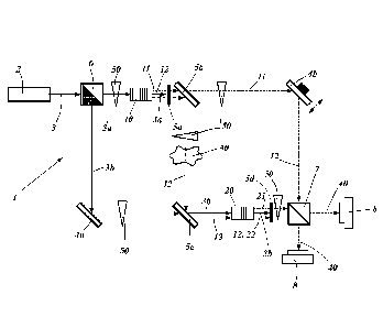
Figure 1 shows a first embodiment of the apparatus of the invention in a Mach-
Zehnder-Interferometer configuration. A pump source 2 emits a pump beam 3,
preferably a laser beam. The pump beam 3 is split on a pump beam separation
means, here a pump beam splitter 6 splits the pump beam 3 into two coherent
pump beams 3a and 3b. The pump beam splitter 6 can be a normal beam splitter
or a polarizing beam splitter with an additional wave plate (not shown) to
rotate
the polarization of one of the pump beams 3a or 3b in order to pump a first
and
Date Recue/Date Received 2022-11-18
18
second field generation means 10 or 20. The polarization of the first and/or
the
second pump beams 3a and 3b can be rotated by a wave plate (not shown) to
enable the pump of the first and second field generation means 10 and 20. For
that, the first pump beam 3a is guided into the first generation means 10 and
the
second pump beam 3b is guided by a first mirror 4a into the second generation
means 20. In the path of the second pump beam 3b a third dichroic mirror 5c is
arranged allowing the second pump beam 3b to travel through the third dichroic
mirror 5c.
As described above, the first generation means 10 is pumped by the first pump
beam 3a, generating a first signal field 11 and first idler field 12. The
first pump
beam 3a is blocked after the first generation means 10 by a first dichroic
mirror 5a
allowing the first signal field 11 and first idler field 12 to pass through.
The first signal field 11 and first idler field 12 are then separated on a
separation
means, in figure 1 on a second dichroic mirror 5b. The first signal field 11
is
transmitted through the second dichroic mirror 5b and travels guided by second
mirror 4b, preferably by a movable mirror to a beam splitter 7.
The first idler field 12 is reflected on the second dichroic mirror 5b and
interacts by
transmission and/or reflection with an object 30. The first idler field 12 is
then
guided by the third dichroic mirror Sc into the second generation means 20.
The second generation means 20 is pumped by the second pump beam 3b,
generating a second signal field 21 and second idler field 22. In and/or
behind the
second generation means 20 the first idler field 12 overlaps spatially with
the
second idler field 22, such that the two fields are indistinguishable. The
second
pump beam 3b and the overlapping first and second idler fields 12 and 22 are
blocked by a fourth dichroic mirror 5d whereas the second signal field 21 is
transmitted and guided on the beam splitter 7.
Date Recue/Date Received 2022-11-18
19
A Mach-Zehnder-lnterferometer is created with an upper and a lower
interferometer-arm between the pump beam splitter 6 and the beam splitter 7.
The first and second signal fields 11 and 21 interfere on the beam splitter 7.
On
both outputs of the beam splitter 7, detection means, preferably CCD cameras
are
arranged to detect the intensity pattern of the interfered signal field 40.
The phase shift a is generated by one or more phase shifting means 50. In
figure
1 more phase shifting means 50 are depicted whereas only one but also more
phase shifting means 50 can be arranged in the apparatus for imaging and
spectroscopy 1. In figure 1, only as an example, the phase shifting means 50
are
shown on more places. The phase shifting means 50 can be the second mirror 4b
by translation of the mirror preferably movable by a piezo element. The phase
shifting means 50 can also be a fiber expander (for a fiber interferometer
setup),
and/or a tilting plane-parallel plate, and/or an optical element introducing a
frequency difference between the two pump beams 3a and 3b, and/or an EOM
(electro optic modulator) and/or wave plates and/or a polarizing beam splitter
and/or a polarizer by changing the polarization, and/or plane-parallel plate
by
tilting the plate, and or a birefringent plate by tilting the plate.
The possible places of the phase shifting means 50 are in the first signal
field Si
11 and/or, in the second signal field 52 21 and/or, in the first idler field
ii 12 and/or,
in the second idler field i2 22 and/or, in the first pump beam 3a and/or, in
the
second pump beam 3b.
Figure 2 shows a second embodiment of the apparatus of the invention in a
Fizeau-Interferometer configuration. The pump source 2 emits a pump beam 3
which is transmitted through a first dichroic mirror 5a and pumps a generation
means 10, wherein the generation means 10 acts in this pump direction as a
first
generation means 10 and generates the first signal field 11 and the first
idler field
12.
Date Recue/Date Received 2022-11-18
20
The first signal field 11 and the pump beam 3 transmit through a second
dichroic
mirror 5b and are reflected on the first mirror 4a, preferably on the movable
first
mirror 4a. After the reflection on the first mirror 4a the signal field 11 and
the
pump beam 3 are transmitted through the dichroic mirror 5b a second time and
are guided into the generation means 10.
The first idler field 12 is reflected on the second dichroic mirror 5b and
interacts
with the object 30 by transmission and/or reflection and is guided by a second
.. mirror 4b back on the second dichroic mirror 5b and is guided into the
generation
means 10.
By the second time, the generation means is pumped from the right side in
figure
2 by the pump beam 3, the generation means 10 acts as a second generation
means by this pump direction generating the second signal field 21 and second
idler field 22. The first signal field 11 and the second signal field 21
overlap
spatially in and behind the generation means 10, such that the signal fields
interfere. The first idler field 12 and the second idler field 22 overlap
spatially in
and behind the generation means, such that the paths of the first idler field
12 and
the second idler field 22 are indistinguishable. The interfered signal fields
40 are
reflected on the first dichroic mirror and detected by the detection means.
As in figure 1, here in figure 2 more phase shifting means 50 are depicted
whereas only one but also more phase shifting means 50 can be arranged in the
apparatus for imaging and spectroscopy 1. In figure 2, only as an example, the
phase shifting means 50 are shown on more places. The phase shifting means 50
can be the first mirror 4a by translation of the mirror, preferably movable by
a
piezo element. The phase shifting means 50 can be the second mirror 4b by
translation of the mirror (not shown in Fig. 2), preferably movable by a piezo
element. The phase shifting means 50 can also be a fiber expander (for a fiber
interferometer setup), and/or a tilting plane-parallel plate, and/or an
optical
Date Recue/Date Received 2022-11-18
21
element introducing a frequency difference between the two pump beams 3a and
3b, and/or an EOM (electro optic modulator) and/or wave plates and/or a
polarizing beam splitter and/or a polarizer by changing the polarization,
and/or
plane-parallel plate by tilting the plate, and or a birefringent plate by
tilting the
plate.
The possible places of the phase shifting means 50 are in the first signal
field 51
11 and/or in the first idler field ii 12 and/or in the pump beam 3.
Figure 3 shows a third embodiment of the apparatus of the invention in a
Fizeau -
Interferometer-like configuration. The difference to figure 2 is that in
figure 3 the
first dichroic mirror 5a is replaced by a beam splitter 7, and the first
signal field 11
is reflected on the surface of the generation means 10 to change the pump
direction for the generation of the second signal 21 and idler 22 fields. Only
the
first idler beam is transmitted through the surface, interacts with the object
and is
guided back in the generation means 10.
Figure 4 shows a fourth embodiment of the apparatus of the invention in a Mach-
Zehnder-lnterferometer setup with BBO-crystals.
The pump source 2 emits a pump beam 3 which is split into a first and a second
pump beam 3a and 3b, whereas the polarization can be adjusted by a wave plate
(not shown) to pump the first and second generation means 10 and 20. In this
embodiment, the first and second generation means 10 and 20 are BBO crystals,
emitting the first signal field 11 and the first idler field 21 in the first
generation
means 10, and the second signal field 21 and the second idler field 22 in the
second generation means 20 under a specific angle.
The first generation means 10 pumped by the first pump beam 3a generates the
first signal field 11 and the first idler field 21. The first signal field 11
is reflected on
the first mirror 4a, preferably on a movable mirror and guides the first
signal field
Date Recue/Date Received 2022-11-18
22
11 into the beam splitter 7. The first idler field 12 interacts with the
object 30 by
transmission and/or reflection and is guided into the second generation means
20.
The second generation means 20 pumped by the second pump beam 3b
generates the second signal field 21 and the second idler field 22. The first
and
second idler fields 12 and 22 overlap spatially in and behind the second
generation means 20 such that the first and second idler fields 12 and 22 are
indistinguishable. The second signal field 21 is guided to the beam splitter 7
and
interferes with the first signal field 11 on the beam splitter. On both output
arms of
the beam splitter, detection means 8 are arranged to detect the interfered
signal
fields 40.
As before, here in figure 4 more phase shifting means 50 are depicted whereas
the only one or more phase shifting means 50 can be arranged in the apparatus
for imaging and spectroscopy 1. In figure 4, only as an example, the phase
shifting means 50 are shown on more places. The phase shifting means can be
the first mirror 4a by translation of the mirror, preferably movable by a
piezo
element. The phase shifting means 50 can also be a fiber expander (for a fiber
interferometer setup), and/or a tilting plane-parallel plate, and/or an
optical
element introducing a frequency difference between the two pump beams 3a and
3b, and/or an EOM (electro optic modulator) and/or wave plates and/or a
polarizing beam splitter and/or a polarizer by changing the polarization,
and/or
plane-parallel plate by tilting the plate, and or a birefringent plate by
tilting the
plate.
The possible places of the phase shifting means 50 are in the first signal
field Si
11 and/or in the second signal field 52 21 and/or in the first idler field ii
12 and/or,
in the second idler field i2 22 and/or in the first pump beam 3a and/or in the
second pump beam 3b.
Date Recue/Date Received 2022-11-18
23
The project leading to this application has received funding from the European
Union's Horizon 2020 research and innovation program under grant agreement
No 801060.
Date Recue/Date Received 2022-11-18
24
Reference List:
1 apparatus for imaging and spectroscopy
2 pump source
3 pump beam
3a first pump beam
3b second pump beam
4a first mirror
4b second mirror
5a first dichroic mirror
5b second dichroic mirror
5c third dichroic mirror
5d fourth dichroic mirror
6 pump beam splitter
7 beam splitter (BS)
8 detection means
10 first field generation means
11 first signal field
12 first idler field
20 second field generation means
21 second signal field
22 second idler field
object
interfered signal field
25 50 phase shifter
Date Recue/Date Received 2022-11-18