Note : Les descriptions sont présentées dans la langue officielle dans laquelle elles ont été soumises.
CA 03112337 2021-03-10
1
DOUGH STRIP SHAPING MEMBER HAVING A CUTTING DEVICE
The present invention relates to a device for shaping several dough strips
according to the
generic terms of patent claim 1.
Dough strip shaping members for shaping dough loads into dough strips are
widely known in
the prior art. Systems known in the prior art consist primarily of feeding
devices, pre-portioning
devices which reduce the dough load for reshaping, and dough strip shaping
units.
These dough strip shapers consist of at least two or more rolls with uniform
or varying
diameters. The rolls can also be produced with various surfaces or profiles.
The length of the
rolls primarily determines the width of the dough strips to be produced. For
baked goods, these
dough strips are of a single section or multiple lengthwise and width-wise
sections, depending
on the product. For lengthwise cutting, that is, for dividing the dough strip
into several dough
strip strands along its width, two methods are known in the art. In the first,
the edges of the
dough strip are cut, so that a major portion of the dough strip is accrued as
waste, and in the
second method the dough strip is cut without edge removal, which has the
advantage that no
edge waste accrues, and allows a saving of up to 15% of the mass that is to be
processed.
In known devices and methods for cutting the dough strip with edge portion,
the dough strip is
produced in the dough strip shaper and, on leaving the dough strip shaper or
at other points of
the dough strip apparatus, the dough strip, according to the shape, is cut
lengthwise into one or
more strips or dough strip strands. This cutting is done using a disc cutter,
punching die, water
jet or the like. With systems of this type, to obtain uniform dough strip
strands, a certain edge
(10 ¨ 15%) is cutoff.
With known devices and methods for cutting the dough strip without edge
cutting, the dough
strip is produced in the dough strip shaper and, after leaving the dough strip
shaper or at other
points in the dough strip apparatus, is cut, wherein, in order to obtain
uniform cross-sections, it
is necessary to perform the cutting in the flow direction in a so-called
calibration unit. To keep
the cross-section uniform, extensive lateral guides are necessary which, to
avoid dough
adhering, must move along with the cutting device or must be provided with
dividing means.
Date Recue/Date Received 2021-03-10
CA 03112337 2021-03-10
2
The disadvantage of systems known from the prior art, therefore, is that a
large edge portion of
the dough Is lost and/or an additional module or additional station in the
dough strip apparatus
becomes necessary, appreciably increasing the complexity, maintenance,
cleaning and costs.
It is thus the object of the invention to provide a device which makes
possible lengthwise cutting
of the dough strip that is economical and simple to operate, allows a high
degree of precision in
cutting the dough strip strands, and produces little or no wasted dough.
This object is fulfilled by the identifying features of patent claim 1,
wherein it is foreseen that the
device comprises a cutting roll, which in particular is power-operated and is
arranged inside the
dough chamber,
- wherein one of the shaping rolls or the cutting roll with the discharge
roll are arranged at a
distance from one another so that dough can be shaped, between one of the
shaping rolls or
the cutting roll, to a defined thickness as a shaped dough strip,
- wherein the cutting roll comprises a number of cutting blades,
particularly disc-shaped, which
extend to the outer perimeter of the discharge roll and wherein the cutting
roll is arranged along
with the discharge roll in the area of the outlet of the dough chamber in such
a way that the
cutting blade divides the dough strip shaped in the dough chamber along the
width of the dough
strip into a number of dough strip strands.
As a result of the inventive device, it is possible to execute the lengthwise
cuts directly in the
dough strip calibration unit or in the dough strip shaper, further making
stations in the dough
strip apparatus superfluous and reducing the length of the dough strip
apparatus and the space
required for it. No border section and thus no waste occurs, and thus profit
is increased and no
foodstuffs are wasted.
In addition, the dough strip is fed through the cutting roll and the discharge
roll as well as the
lateral coverings during cutting on four sides, resulting in a uniform shape
and width and thus
increased precision of the dough strip strands.
Particularly advantageous embodiments of the invention are defined in greater
detail by the
features of the dependent claims.
Improved quality of cutting is achieved in that the discharge roll is
configured as a counter-roll
for the cutting roll, wherein the cutting blades of the cutting roll extend to
the discharge roll,
Date Recue/Date Received 2021-03-10
CA 03112337 2021-03-10
3
wherein the cutting blades in particular comprise a greater cutting depth than
the shaped dough
strip, so that the dough strip undergoes no reshaping between the discharge
roll and the cutting
roll.
The thickness of the dough strip can advantageously be adjusted if the device
includes a pivot
device, wherein a number of the shaping rolls, in particular all shaping rolls
that, each seen on a
common side of the dough chamber with respect to the thickness of the dough
strip, are arranged on
the same side, and/or the discharge rolls are connected with the pivot device
and can be pivoted by
means of the pivot device in the direction of the thickness of the dough
strip, wherein the distance of
the axes of the shaping rolls and/or of the discharge roll that are connected
with the pivot device can
be adjusted to the axes of at least one, in particular of all, of the
respective other shaping rolls not
connected with the pivot device and/or of the discharge rolls and in this way
the thickness of the
dough strip can be modified and/or pre-set.
The thickness of the dough strip can advantageously be adjusted if the device
includes a pivot
device, wherein a number of the shaping rolls, in particular all shaping rolls
that, each seen on a
common side of the dough chamber with respect to the thickness of the dough
strip, are arranged on
the same side, and/or the discharge rolls are connected with the pivot device
and can be pivoted by
means of the pivot device in the direction of the thickness of the dough
strip, wherein the distance of
the axes of the shaping rolls and/or of the discharge roll that are connected
with the pivot device can
be adjusted to the axes of at least one, in particular of all, of the
respective other shaping roll not
connected with the pivot device and/or of the discharge roll and in this way
the thickness of the
dough strip can be modified and/or pre-set.
It can advantageously be foreseen that the device, in particular the pivot
element, comprises a
pivot drive, particularly a hydraulic or pneumatic or electrical or
electromechanical pivot drive,
wherein the pivot drive is arranged and configured in such a way that a number
of the shaping
rolls, particularly all shaping rolls that, each seen on a common side of the
dough chamber with
respect to the thickness of the dough strip, are arranged on the same side
and/or the discharge
roll in the direction of the thickness of the dough strip can be powered
oscillating about a neutral
point, so that the distance of the axes of the shaping rolls and/or of the
discharge roll, which can
be moved in an oscillating manner by the pivot drive, from the axes of at
least one, particularly
of all, of the respective other shaping rolls not powerable by the pivot drive
and/or from the axis
of the discharge roll oscillating in the dough production process are
displaced by a preset
distance. Owing to the oscillation movement of the individual rolls, the dough
quality is improved and
Date Recue/Date Received 2021-03-10
CA 03112337 2021-03-10
4
a homogeneous dough strip is produced, and thus the weight tolerance of the
dough pieces is
considerably reduced. In addition, the removal of dough from individual rolls
is facilitated.
The distance of the shaping rolls from one another can alternatively be easily
modified wherein
the pivot element includes a control element, which is preferably lengthwise
adjustable, in
particular a hydraulic or pneumatic cylinder or electromechanical actuators,
wherein the pivot
drive comprises an eccentric mechanism, powered by a motor, wherein the
placement element
is connected at one end with the pivot lever and at the other end with the
eccentric mechanism,
wherein the pivot lever, with the motor powered, can be pivoted about the
pivot axis by the
eccentric mechanism and the control element, oscillating about a neutral
point.
Owing to the displacement by means of the control element, a wider
displacement distance is
possible. The lateral wall or the cover of the device can be folded open and
the shaping rolls
can then easily be removed and cleaned in their unfolded state.
To allow simple removal and displacement of the cutting rolls, it can be
foreseen that the cutting
roll is arranged on a displacement device, wherein the distance and/or the
pressure force of the
cutting roll on the discharge roll can be adjusted by means of the
displacement device, wherein
the displacement device in particular is configured as a pivot arm that is
displaceable about an
axis, and on which the cutting roll is arranged.
The lateral edges of the cut dough strip strands are improved in that the
discharge roll and/or
the cutting roll comprise two lateral walls, each of which is arranged in the
area at the end of the
discharge roll and/or of the cutting roll, wherein the lateral walls are
arranged and configured in
such a way that, upon cutting the dough strip with the cutting roll,
misshaping and deflection of
the dough strip are prevented.
To prevent accumulation of the dough, it can be arranged that the device
includes a number of
scrapers, wherein the scrapers each are contiguous with the periphery of the
shaping roll,
wherein dough from the periphery of the respective shaping roll can be removed
by means of
the scrapers or wherein the device includes a number of milling devices and/or
a number of
spraying elements, wherein the milling devices and/or the spray elements are
arranged in the
device in such a way as to hinder accumulation or sticking of dough on the
surfaces of the
device that come in contact with the dough.
Date Recue/Date Received 2021-03-10
CA 03112337 2021-03-10
To prevent unwanted pressure forces and overflowing of the dough feeder
device, it can be
foreseen that the dough feeder device includes a filler funnel and at least
one filler status
sensor, wherein the filler status of the dough feeder device, in particular of
the filler funnel, can
be read by means of the filler status sensor.
It can advantageously be provided that the device includes a number of drives,
wherein the
shaping rolls and/or the discharge roll in each case can be powered together
or separately,
preferably at different rotation speeds, or that the device includes two
drives, wherein the
shaping rolls that, each seen on a common side of the dough chamber with
respect to the
thickness of the dough strip, are arranged on the same side, are each powered
together with
one of the two drives and, in particular, are connected with one another by
gears.
A preferred configuration of the device is achieved if the shaping rolls
and/or discharge roll
and/or cutting roll have different profiles, wherein in particular the shaping
rolls comprise a
profiled periphery and the discharge roll and cutting roll are of smooth
configuration.
For easy cleaning and exchange of the cutting roll and/or the blades, it can
be foreseen that the
cutting roll is arranged replaceably on the device.
To allow the thickness of the dough strip produced by the device to be
adjusted automatically
and/or depending on the dough feeder, it can be foreseen that the control
element, particularly
the hydraulic or pneumatic cylinder or the linear elements or the spindle
drive, comprises a
sensor system by which the current length of the control element can be
determined, wherein in
particular by means of the sensors the length of the control element and thus
the thickness of
the dough strip can be adjusted on the basis of previously determined or
recorded weights of
the dough pieces.
Additional advantages and configurations of the invention can be seen from the
description and
the attached drawings.
BRIEF DESCRIPTION OF THE DRAWINGS
The invention is schematically depicted hereinafter by means of particularly
advantageous
embodiments, which are not, however, to be understood as restrictive, and
shown schematically
in the drawings and described by way of example with reference to said
drawings.
Date Recue/Date Received 2021-03-10
CA 03112337 2021-03-10
6
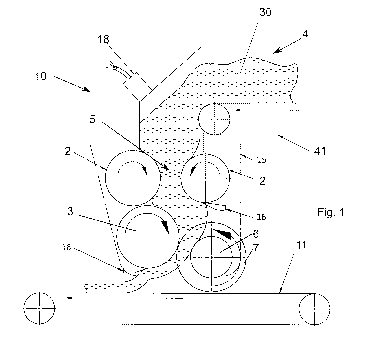
FIG. 1 shows a first embodiment of an inventive device in sectional view.
FIG. 2 shows an embodiment of the invention with six rolls.
FIG. 3 shows an additional embodiment of the inventive device with dough
feeder attachment.
FIG. 4 shows a view of the device seen in an explosion drawing according to
FIG. 3.
FIG. 5 shows an alternative embodiment of the invention with slightly adjusted
dough strip
thickness.
FIG. 6 shows a detail view of the eccentric mechanism of the oscillation unit.
FIG. 7 shows a lateral view of the device with large adjusted dough strip
thickness.
BRIEF DESCRIPTION OF THE EMBODIMENTS
FIG. 1 depicts an embodiment of the device 10 for shaping several dough strip
strands in a
simplified section view. The device 10 includes four rolls, each of which can
be rotated by a
drive 21 about its axis, two shaping rolls 2, a discharge roll 3 and a cutting
roll 6. Dough 30 is
fed by way of a dough feeding device 4, by means of a conveyor belt 41 in the
flow direction of
the dough above the two first shaping rolls 2.
The axes of the shaping rolls 2 and of the discharge roll 3 are arranged
parallel to one another
at a distance and, between the shaping rolls 2 and the discharge roll 3,
configure a dough
chamber 5 in which the dough 30 is worked and shaped as a dough strip. In
addition the device
includes two lateral coverings 15, which are contiguous with the front end of
the shaping rolls
2 and the discharge roll 3 and laterally delimit the dough chamber 5 and
reinforce it against the
surroundings. The dough 30 is drawn into the dough chamber 5 through the
mirror-inverted
rotation of the first two shaping rolls 2, worked between the shaping rolls 2,
possible dough
pieces are made uniform and thus a continuous endless dough strip is produced.
The device 10 includes a cutting roll 6, which is arranged inside the dough
chamber 5 at its
outlet. The axis of the cutting roll 6 is arranged parallel to the axes of the
shaping rolls 2 and the
discharge roll 3. The cutting roll 6 comprises a number of disc-shaped cutting
knives 7, which
extend from the periphery of the cutting roll 6 in the direction of the
discharge roll 3 all the way
Date Recue/Date Received 2021-03-10
CA 03112337 2021-03-10
7
to its periphery. The dough strip is removed from the dough chamber 5 between
the discharge
roll and the cutting roll 6, wherein the dough strip is cut into a number of
dough strip strands
corresponding to the number of cutting blades 7. The width of the dough strip
strands is
determined by the distance between the cutting blades 7 and the distance of
the cutting blades
7 situated close on the cutting roll 6 in the lengthwise direction of the
front end of the cutting roll
6. The thickness of the dough strip is determined in the embodiment shown in
FIG. 1 by the
distance of the discharge roll 3 with the cutting roll 6. The discharge roll 3
in this embodiment
forms a counter-roll for the cutting roll 6, with which the cutting blades 7
are contiguous and
pressured.
At the outlet of the dough chamber 5, the dough strips cut by the cutting roll
6 are transported by
a dough delivery device 11, which is configured as a transport belt, out of
the device 10 and into
the dough strip appliance for further processing.
Depicted in FIG. 2 in a schematic section view is an additional embodiment of
the inventive
device 10. The device 10 includes four shaping rolls 2. The dough 30 is
conveyed by way of the
dough feeding device 4 through a dough funnel by gravitational force to the
first two shaping
rolls 2 and drawn between them into the dough chamber 5. Between the shaping
rolls 2, the
dough strip can be worked and made uniform, depending on the type of dough,
and shaped as
a dough strip with defined thickness between the final shaping rolls 2, that
is, those situated
closest to the outlet of the dough chamber 5, and shaped to the discharge roll
3. The dough
strip shaped in this way is then cut into dough strip strands with defined
width between the
discharge roll 3 and the cutting roll 6 and discharged from the device 10 by a
dough ejecting
device 11. The dough strip in this embodiment is no longer reshaped between
the cutting roll 6
and the discharge roll 3.
FIG. 3 depicts an additional embodiment of the device 10 in a schematic
lateral view. The
device 10 comprises eight shaping rolls 2, arranged in two rows with four
shaping rolls 2 each
bordering the dough chamber 5 laterally or arranged on the same side with
respect to the
thickness of the dough strip. The shaping rolls 2 along with their periphery
are contiguous with
one another and have the same diameter. The two rows of shaping rolls 2 are
arranged with
respect to one another in funnel shape, so that in each case the distance
between the axes of
the shaping rolls 2 arranged in each case at the same height in the dough
chamber 5 are
tapering in the direction from the entrance of the dough chamber 5 to the
outlet. The thickness
of the dough strip is then determined between the final two shaping rolls 2
which are arranged
Date Recue/Date Received 2021-03-10
CA 03112337 2021-03-10
8
closest to the outlet of the dough chamber 5. The dough strip is then fed
between the periphery
of the discharge roll 3 and the cutting roll 6 and there cut into a number of
dough strip strands
and expelled from the device 10 by means of a conveyor belt or a spreading
apparatus in which
the dough strip strands are separated from one another.
To prevent sticking of the dough 30, especially sticky dough with high water
content, on the
conveyor belts 41, transport rolls and rolls, so-called optional severing
means can be employed.
The severing means, flour, water and the like, can for example be applied by a
number of
milling devices 23 and/or a number of spray elements 24. The milling devices
23 provide, on the
belts and surfaces of the dough strips, a flour-film, which adheres to them
and separates the
dough strip or the dough from the parts of the device 10. Thereafter, scrapers
16 are arranged
on the final dough strip shaping rolls in order to prevent possible adherences
or to separate or
scrape the dough more easily from them. If no separating flour is desired in
certain doughs, for
example, gluten-free doughs, then a separating film of water or oil can
replace the flour-film by
means of the spray elements 24.
As shown in FIGS. 1 and 3, the device 10 can include a number of scrapers 16,
which are each
contiguous with the periphery of one or more of the shaping rolls 2, in each
case the final two
shaping rolls 2 in the conveyance direction of the dough. The dough is lifted
off by the scrapers
16, or any scraps of dough are scraped off the respective rolls. The scraper
16 of FIG. 1, which
is contiguous with the periphery of the discharge roll 3, also facilitates
removal of the dough strip
strands after cutting by the cutting roll 6.
As depicted in FIGS. 1 through 3, the present level of the dough 30 in the
dough feeding device
4 or the dough funnel can optionally be reported by a filler level sensor 18.
If the level of the
dough climbs too high, the dough feeding device 4 can be halted and any build-
up and/or
undesired misshaping or pressure exertion on the dough 30 can be prevented.
FIG. 4 shows a lateral view of the device 10 according to FIG. 3 facing the
periphery of one of
the rows of shaping rolls 2. The shaping rolls 4 are each mounted on the front
ends in the lateral
coverings 15. The device 10 further comprises a drive 21, which is connected
with the shaping
rolls 2 by toothed wheels. The shaping rolls are each powered uniformly with
one another by the
drive 21, wherein the toothed wheels between the shaping rolls 2 transmit the
rotary movement
to the respective next one. The cutting roll 6 is likewise connected by a
toothed wheel with the
shaping rolls 2 or with the drive. The rotation speed of the shaping rolls 2
of the discharge roll 3
Date Recue/Date Received 2021-03-10
CA 03112337 2021-03-10
9
and of the cutting roll 6 can be identical or optionally different. The
cutting disc 6 comprises five
cutting knives 7, which are configured in disc form and extend to the
periphery of the discharge
roll 3 (FIG. 3). The lateral coverings 15 delimit the dough chamber 5
laterally and thus
determine the width of the dough strip. The dough strip in the embodiment of
FIGS. 3 and 4 is
cut in uniformly wide dough strip strands, whose width is determined by the
distance of the
cutting knives 7 from one another or the lateral coverings 15.
FIG. 5 shows an additionally optional embodiment of the inventive device 10
with a view toward
the front ends of the rolls. The device 10 comprises eight shaping rolls 2,
each in two rows of
four shaping rolls 2, which delimit the dough chamber laterally or are
arranged on the same side
in relation to the thickness of the dough strip. The shaping rolls 2 are each
arranged at a
distance from the neighboring one so that they are distanced at their
periphery. The shaping
rolls 2 comprise different diameters, so that the diameter of the shaping
rolls 2 decrease from
the entry of the dough chamber to the outlet of the dough chamber 5. The two
rows of shaping
rolls 2 are arranged in funnel shape toward one another, so that the distance
between the axes
of the shaping rolls 2 arranged at the same height in the dough chamber 5
tapers in each case
from the entry into the dough chamber 5 as far as the outlet. The device 10
comprises two
drives 21, which are configured as motors. The two drives 21 each power the
shaping rolls 2 of
the respective side of the dough chamber 5 together. The discharge roll 3 is
configured as a
counter-roll for the lateral roll 6, wherein the cutting knives 7 of the
cutting roll 6 extend all the
way to the discharge roll 3. The cutting knives 7 comprise a greater cutting
depth than the
shaped dough strip, so that the dough strip undergoes no misshaping between
the discharge
roll 3 and the cutting roll 6.
The device 10 comprises a pivot element 8, with which the four shaping rolls 2
that, each seen
on a common side of the dough chamber with respect to the thickness of the
dough strip, are
arranged on the same side, can be pivoted or displaced in the direction of the
thickness of the
dough strip. The distance of the axes of the shaping rolls 2, which are
connected with the pivot
element 8, is thereby displaced to the axes of all other shaping rolls 2 not
connected with the
pivot element 8. The thickness of the dough strip can be modified and preset
thereby.
The pivot element 8 comprises two pivot levers 8 arranged parallel to one
another in the
direction of the width of the dough chamber 5. The four shaping rolls 2, that,
each seen on a
common side of the dough chamber with respect to the thickness of the dough
strip, are
arranged on the same side, are mounted on the pivot levers 81. Upon pivoting
of the pivot lever
Date Recue/Date Received 2021-03-10
CA 03112337 2021-03-10
8, the distance of the axes of the shaping rolls 2, which are mounted in the
pivot lever 81, from
the respective other shaping rolls 2 not mounted in the pivot lever 81,
arranged jointly on the
other side of the dough chamber, can be displaced and/or adjusted.
The pivot element 8 further comprises a pivot drive 20, which includes an
electric motor 12.
Connected with the electric motor 12 is an eccentric mechanism 13, with a
defined eccentricity 3
(FIG. 6), which rotates with the motor 12 in operation. Arranged between the
eccentric
mechanism 13 and the pivot lever 81 is a control element 13, configured as a
hydraulic cylinder
14. The hydraulic cylinder 14 is connected at one end on the piston on the
eccentric mechanism
13 and at the other end or with the housing on the pivot lever 81. If the
eccentric mechanism 13
is powered by the motor 12, the pivot lever 81 is pivoted by the hydraulic
cylinder 14 oscillating
about the pivot axis 82 by a pre-defined value. By means of the oscillating
pivoting movement of
the pivot axis 81 in the dough strip production process, the dough quality of
the dough strip is
improved and the quality of the cuts of the dough strip into dough strip
strands is improved.
Optionally, as depicted in FIGS. 5 and 7, the control means can be configured
for lengthwise
adjustability. Thus the hydraulic cylinder 14 can be inserted or removed by
applying pressure,
electric power or control signals, whereby the distance X and thereby the
distance of the axes of
the shaping rolls 2 affixed to the pivot lever 81 from the shaping rolls 2 not
affixed to the pivot
lever 81 or to the pivot device 8, can be modified. In FIG. 5 the device 10 is
depicted with a
small distance X and in FIG. 7 with a great distance X. Upon modifying the
distance X, the
thickness of the dough strip can be altered or the device 10 can be brought
into a cleaning
position in which the individual rolls and the dough chamber 5 are accessible
by simple means
and thus can be cleaned easily.
Alternatively, the control element, rather than as hydraulic cylinder 14, can
also be configured
as a linear element, spindle gears, etc., so that the distance of the axes of
the shaping rolls can
be modified by displacing the linear element, spindle gear, etc.
The cutting roll 6 is arranged on a displacement device 25. The displacement
device 25 is
configured as a pivot arm 26 that can move about an axis, by which the
distance and/or the
pressure force of the cutting roll 6 on the discharge roll 3 can be adjusted.
Alternatively, it can be foreseen that the pivot drive 20 is configured
pneumatically or electrically
or electromechanically.
Date Recue/Date Received 2021-03-10
CA 03112337 2021-03-10
11
Optionally, the discharge roll 3 or the cutting roll 6 can comprise two
lateral walls 31 (FIG. 6),
each of which is arranged in the area of an end of the discharge roll 3 and/or
of the cutting roll 6.
The lateral walls 31, in cutting the dough strip with the cutting roll 6, make
it possible to prevent
misshaping and a deflection of the dough strip and can cause a clean cutting
shape.
In another option, the shaping rolls 2 and/or the discharge roll 3 and/or the
cutting roll 6 can
have a different profile, wherein in particular the shaping rolls 3 comprise a
profiled periphery
and the discharge roll 3 and the cutting roll 6 are of smooth configuration.
Optionally it can be foreseen that the control element, in particular the
hydraulic or pneumatic
cylinder 14 or the linear elements or the spindle gears, comprise a sensor
system. The current
length of the control element is recorded by means of the sensor system. By
the sensor system,
then, the length of the control element and thus the thickness of the dough
strip can be set or
modified on the basis of previously determined or entered weights of the dough
pieces.
Date Recue/Date Received 2021-03-10