Note : Les descriptions sont présentées dans la langue officielle dans laquelle elles ont été soumises.
CA 03112978 2021-03-16
WO 2020/060683
PCT/US2019/045218
DISPENSER FOR DISPOSABLE UTENSILS
BACKGROUND
Field
[0001]
Embodiments described generally relate to utensil dispensers and methods for
making and using same. More particularly, embodiments described relate to
utensil dispensers
having improved dispense mechanisms, as well as methods for making and using
same.
Description of the Related Art
[0002]
Disposable utensils can typically be found in fast-food and take out
restaurants.
Conventional utensil dispensers have been used to provide a confined and
controlled protective
environment for utensils housed within. Such assemblies, however, have
challenges and issues
delivering utensils to a consumer in a repeatable and reliable manner.
Conventional assemblies
typically suffer from one or more utensils getting jammed within the dispenser
housings and
not being able to be dispensed without time consuming attention and
disassembly, which
exposes the contents inside, i.e. the utensils, to the surrounding
environment. Conventional
assemblies also have difficulties associated with re-loading utensils and
maintaining a reliable
supply of utensils for user demand.
[0003] There is
a need, therefore, for a utensil dispenser that can supply utensils to users
in a reliable and sanitary manner.
SUMMARY
[0004] Utensil
dispensers and methods for making and using the same are provided herein.
In some examples, the utensil dispensers can include a housing configured to
contain a stack
of the utensils therein, wherein the stack of the utensils comprises at least
one utensil in addition
to a next utensil and each utensil comprises at least one contoured projection
extending
outwardly therefrom; a front pedestal disposed inside the housing, the front
pedestal configured
to support the at least one contoured projection extending outwardly from the
next utensil; and
a moveable member disposed within the housing and configured to move from a
ready position
to a dispense position, the moveable member comprising at least one extension
arm configured
with at least one engaging section, wherein the engaging section is capable of
receiving the
contoured projection extending outwardly from the next utensil.
- 1 -
CA 03112978 2021-03-16
WO 2020/060683
PCT/US2019/045218
[0005] A
utensil dispenser can also include a housing configured to contain a stack of
the
utensils therein, wherein the stack of the utensils comprises at least one
utensil in addition to a
next utensil and each utensil comprises at least one contoured projection
extending outwardly
therefrom; a front pedestal disposed inside the housing, the front pedestal
configured to support
the at least one contoured projection extending outwardly from the next
utensil; a rear pedestal
disposed inside the housing, the rear pedestal configured to support a handle
end of the next
utensil; a dispensing mechanism disposed within the housing, the dispensing
mechanism
comprising at least two engaging surfaces configured to move back and forth; a
moveable
member disposed within the housing and configured to move from a ready
position to a
dispense position due to the back and forth movement of the dispensing
mechanism, the
moveable member having at least one extension arm extending away from the rear
pedestal
and configured with at least one engaging section proximate a distal end
thereof, wherein the
engaging section is capable of receiving at least a portion of the contoured
projection extending
outwardly from the next utensil.
[0006] A
utensil dispenser can also include a housing configured to contain a stack of
the
utensils therein; an access port providing an opening to the housing; a drive
mechanism
configured to contact and release a utensil from the lowermost position of the
stack; and an
inclined surface located beneath the stack of utensils, the inclined surface
comprising a
positioning mechanism formed thereon.
[0007] A
utensil dispenser can also include a housing configured to contain a stack of
the
utensils therein; an access port providing an opening to the housing; a drive
mechanism
configured to contact and release a utensil from the lowermost position of the
stack; an inclined
surface located beneath the stack of utensils; and an actuator that is
operably connected to the
drive mechanism, the actuator configured to move the drive mechanism between a
ready
position and dispense position, wherein the actuator comprises: a body that is
pivotably
mounted to the housing, an opening formed through a lower portion of the body,
and at least
one arm located proximate the opening and extending from the body toward the
access port.
[0008] A
utensil dispenser can also include a housing configured to contain a stack of
the
utensils therein, wherein the stack of the utensils comprises at least one
utensil in addition to a
next utensil; an access port providing an opening to the housing; a drive
mechanism configured
to contact the next utensil; an actuator that is operably connected to the
drive mechanism and
- 2 -
CA 03112978 2021-03-16
WO 2020/060683
PCT/US2019/045218
configured to move the drive mechanism where the drive mechanism pushes the
next utensil
in the stack causing the next utensil to release from the stack of the
utensils; and a prime
mechanism configured to move the actuator and the drive mechanism between a
ready position
and a dispense position, the prime mechanism comprising a primer handle
mechanically linked
to a ratchet having one or more teeth for engaging a pawl that is disposed on
an inner wall of
the housing.
[0009] A
utensil dispenser can also include a housing configured to contain a stack of
the
utensils therein, wherein the stack of the utensils comprises at least one
utensil in addition to a
next utensil and each utensil comprises at least one contoured projection
extending outwardly
therefrom; a front pedestal disposed inside the housing, the front pedestal
configured to support
at least one of the at least one contoured projections extending outwardly
from the next utensil;
and a moveable member disposed within the housing, the moveable member having
an
engaging section capable of engaging the contoured projection extending
outwardly from the
next utensil, the moveable member configured to move from a ready position to
a dispense
position.
[0010] Methods
for using and operating a utensil dispenser can include: pulling a handle
end of a utensil extending from a housing configured to contain a stack of
utensils therein, each
utensil comprising at least one contoured projection extending outwardly
therefrom and
supported on a front pedestal disposed inside the housing; triggering a
movement of a first
portion of a dispensing mechanism to move an extension member within the
housing, the
extension member having an engaging section capable of receiving the contoured
projection
extending outwardly from a utensil located at a bottom of the stack, wherein
generally linear
movement of the extension member releases the utensil from the bottom of the
stack; and
retaining the released utensil within the housing using a second portion of
the dispensing
mechanism, the second portion located beneath the first portion and comprising
an opening to
allow the handle end of the released utensil to pass through and extend
outside the housing.
BRIEF DESCRIPTION OF THE DRAWINGS
[00111 Figure 1
depicts a perspective view of an illustrative utensil dispenser, according to
one or more embodiments provided herein.
- 3 -
CA 03112978 2021-03-16
WO 2020/060683
PCT/US2019/045218
[0012] Figure 2
depicts a perspective view of the illustrative utensil dispenser of Figure 1
with an access door open to reveal one or more dispense chassis located
therein, according to
one or more embodiments.
[0013] Figure 3
depicts a side elevation view of an illustrative dispense chassis for use with
the dispenser, according to one or more embodiments provided herein
[0014] Figure 4
depicts an illustrative plan view of a dispense chassis, according to one or
more embodiments.
[0015] Figure
5A depicts a perspective view of a fork for use with the utensil dispenser,
according to one or more embodiments.
[0016] Figure
5B depicts a perspective view of a knife for use with the utensil dispenser,
according to one or more embodiments.
[0017] Figure
5C depicts a perspective view of a spoon for use with the illustrative utensil
dispenser, according to one or more embodiments.
[0018] Figure
6A depicts a cut away side view of the dispense chassis, according to one or
more embodiments provided herein. Several components within the dispense
chassis have
been removed to better illustrate the interior of the chassis body.
[0019] Figure
6B depicts a cut away side view of the dispense chassis, according to one or
more embodiments provided herein.
[0020] Figure
6C depicts an isometric view of the dispense chassis having a portion of the
housing removed to reveal the dispensing mechanism therein, according to one
or more
embodiments provided herein.
[0021] Figure
7A depicts an enlarged cut away side view of the lower portion of the
dispense chassis in a ready to be primed position, according to one or more
embodiments
provided herein.
[0022] Figure
7B depicts an enlarged cut away side view of the lower portion of the
dispense chassis as the primer handle begins to extend from the dispense
chassis, according to
one or more embodiments provided herein.
- 4 -
CA 03112978 2021-03-16
WO 2020/060683
PCT/US2019/045218
[0023] Figure 8
depicts an enlarged cut away side view of the lower portion of the dispense
chassis as the primer handle is fully extended from the dispense chassis,
according to one or
more embodiments provided herein.
[0024] Figure 9
depicts an enlarged cut away side view of the lower portion of the dispense
chassis as the primer handle begins to return or retract into the dispense
chassis, according to
one or more embodiments provided herein.
[0025] Figure
10 depicts an enlarged cut away side view of the lower portion of the
dispense chassis as the primer handle retracts into the dispense chassis,
driving the push arm
forward to release the next utensil from the stack, according to one or more
embodiments
provided herein.
[0026] Figure
11 depicts an enlarged cut away side view of the lower portion of the
dispense chassis as the next utensil releases from the stack and falls onto a
gravity ramp,
according to one or more embodiments provided herein.
[0027] Figure
12 depicts an enlarged cut away side view of the lower portion of the
dispense chassis as the released utensil moves down a gravity ramp and is
caught by an actuator
and held in a dispensing position, according to one or more embodiments
provided herein.
[0028] Figure
13 is another view of Figure 12 but with the utensils removed to better
illustrate the moving parts of the dispense chassis.
[0029] Figure
14 depicts an enlarged cut away side view of the lower portion of the
dispense chassis as the released utensil begins to be dispensed, according to
one or more
embodiments provided herein.
[0030] Figure
15 is another view of Figure 14 but with the utensils removed to better
illustrate the moving parts of the dispense chassis.
[0031] Figure
16 depicts another enlarged cut away side view of the lower portion of the
dispense chassis as the dispensing utensil drives the actuator backwards,
according to one or
more embodiments provided herein.
[0032] Figure
17 is another view of Figure 16 but with the utensils removed to better
illustrate the moving parts of the dispense chassis.
- 5 -
CA 03112978 2021-03-16
WO 2020/060683
PCT/US2019/045218
[0033] Figure
18 depicts an enlarged cut away side view of the lower portion of the
dispense chassis as the dispensing utensil exits the dispense chassis,
triggering the release of
the then next utensil from the stack, according to one or more embodiments
provided herein.
[0034] Figure
19 is another view of Figure 18 but with the utensils removed to better
illustrate the moving parts of the dispense chassis.
[0035] Figure
20 depicts an enlarged cut away side view of the lower portion of the
dispense chassis as the then next utensil lands on the gravity ramp and the
actuator returns to
its resting position, according to one or more embodiments provided herein.
[0036] Figure
21 is another view of Figure 20 but with the utensils removed to better
illustrate the moving parts of the dispense chassis.
[0037] Figure
22 depicts a cut away elevation view of the illustrative dispense chassis in
which the chassis is generally full of utensils, according to one or more
embodiments.
[0038] Figure
23 depicts another illustrative cut away side view of the illustrative
dispense
chassis in which the dispense chassis is between half-full and empty of
utensils, according to
one or more embodiments.
[0039] Figure
24 depicts another illustrative cut away side view of the illustrative
dispense
chassis in which the dispense chassis is almost empty of utensils, according
to one or more
embodiments.
[0040] Figure
25 depicts an illustrative perspective view of the utensil dispenser having
its
access door open, allowing a dispense chassis to be loaded, according to one
or more
embodiments provided herein.
[0041] Figure
26 depicts an illustrative cut away side views of the lower portion of the
illustrative dispense chassis to better illustrate the dispense chassis in a
dispensing position,
according to one or more embodiments provided herein.
[0042] Figure
27 depicts an illustrative cut away side views of the lower portion of the
illustrative dispense chassis to better illustrate the dispense chassis in a
loading position
provided herein.
- 6 -
CA 03112978 2021-03-16
WO 2020/060683
PCT/US2019/045218
[0043] Figure
28 depicts an illustrative cut away perspective view of the lower portion of
the dispenser housing, according to one or more embodiments.
DETAILED DESCRIPTION
[0044] It is to
be understood that the following disclosure describes several exemplary
embodiments for implementing different features, structures, or functions of
the invention.
Exemplary embodiments of components, arrangements, and configurations are
described
below to simplify the present disclosure; however, these exemplary embodiments
are provided
merely as examples and are not intended to limit the scope of the invention.
Additionally, the
present disclosure may repeat reference numerals and/or letters in the various
exemplary
embodiments and across the Figures provided herein. This repetition is for the
purpose of
simplicity and clarity and does not in itself dictate a relationship between
the various exemplary
embodiments and/or configurations discussed in the Figures. Moreover, the
formation of a
first feature over or on a second feature in the description that follows may
include
embodiments in which the first and second features are formed in direct
contact, and may also
include embodiments in which additional features may be formed interposing the
first and
second features, such that the first and second features may not be in direct
contact. Finally,
the exemplary embodiments presented below may be combined in any combination
of ways,
i.e., any element from one exemplary embodiment may be used in any other
exemplary
embodiment, without departing from the scope of the disclosure. The figures
are not
necessarily to scale and certain features and certain views of the figures may
be shown
exaggerated in scale or in schematic for clarity and/or conciseness
[0045]
Additionally, certain terms are used throughout the following description and
claims to refer to particular components. As one skilled in the art will
appreciate, various
entities may refer to the same component by different names, and as such, the
naming
convention for the elements described herein is not intended to limit the
scope of the invention,
unless otherwise specifically defined herein. Further, the naming convention
used herein is not
intended to distinguish between components that differ in name but not
function. Additionally,
in the following discussion and in the claims, the terms "including" and
"comprising" are used
in an open-ended fashion, and thus should be interpreted to mean "including,
but not limited
to." All numerical values in this disclosure may be exact or approximate
values unless
otherwise specifically stated. Accordingly, various embodiments of the
disclosure may deviate
- 7 -
CA 03112978 2021-03-16
WO 2020/060683
PCT/US2019/045218
from the numbers, values, and ranges disclosed herein without departing from
the intended
scope. Furthermore, as it is used in the claims or specification, the term
"or" is intended to
encompass both exclusive and inclusive cases, i.e., "A or B" is intended to be
synonymous
with "at least one of A and B," unless otherwise expressly specified herein.
[0046] The
terms "up" and "down"; "upward" and "downward"; "upper" and "lower";
"upwardly" and "downwardly"; "above" and "below"; and other like terms as used
herein refer
to relative positions to one another and are not intended to denote a
particular spatial orientation
since the apparatus and methods of using the same may be equally effective at
various angles
or orientations.
[0047] Figure 1
depicts a perspective view of an illustrative utensil dispenser 100,
according to one or more embodiments. The utensil dispenser 100 can include a
housing or
body 110 having a base 120 and an access door 130. The base 120 can provide
support for the
dispenser housing 110 and allows the utensil dispenser 100 to be freestanding.
The base 120
can be fixedly attached to the bottom of the dispenser housing 110 using one
or more fasteners
such as screws, bolts, rivets, or any other type of fastener. The dispenser
housing 110 can also
sit on the base 120 without any form of mechanical fastening. The base 120 can
be removable
so that the utensil dispenser 100 can be wall mounted using one more wall
mounting attachment
holes (not shown in these views).
[0048] The
access door 130 can swing opened and closed using one or more hinges
attached to the dispenser housing 110. The hinge locations can vary and can be
located at the
top, bottom, or side of the dispenser housing 110. The access door 130 can
include one or more
fill level apertures or windows 162 that align with corresponding fill level
apertures or windows
172 disposed on the dispense chassis 150. As explained further below with
reference to Figures
22-24, these apertures or windows 162, 172 allow a visual indication of the
stock of utensils
within the dispenser to be visible outside the dispenser 100.
[0049] Figure 2
depicts a perspective view of the illustrative utensil dispenser of Figure 1
with the access door 130 opened to reveal one or more dispense chassis 150
located therein,
according to one or more embodiments. Within the dispenser housing 110, the
utensil
dispenser 100 can include one or more dispense chassis 150 for dispensing a
plurality of
utensils through an access port 152 disposed at one end of each dispense
chassis 150. Each
- 8 -
CA 03112978 2021-03-16
WO 2020/060683
PCT/US2019/045218
dispense chassis 150 can be pre-packaged with utensils (i.e. knife, fork,
spoon, spork, etc.). In
some implementations, the dispense chassis 150 is replaced with a new dispense
chassis 150
and is not reused. In other implementations, the dispense chassis 150 can be
refilled and reused
in the utensil dispenser 100.
[0050] The
utensil dispenser 100 can accept one, two, or three or more dispense chassis
150. The utensil dispenser 100 of Figure 2 is shown with three dispense
chassis 150, e.g., one
for each of a spoon, fork, and knife, but any combination of utensils can be
used. Further, any
of the dispense chassis 150 can be located within any dispensing position
(e.g. left, right,
middle for a 3 chassis dispenser) within the dispenser housing 110.
Accordingly, a dispense
chassis 150 of any type of utensil can be placed into any available position.
[0051] Figure 3
depicts a side elevation view of an illustrative dispense chassis 150 for use
with the dispenser, according to one or more embodiments. The dispense chassis
150 can
include a top 305 disposed on a first or upper end of a chassis body or
chassis housing 310.
The chassis housing 310 can further include a griper or handle 360 formed in a
centrally located
section or portion thereof The handle 360 can provide a point of engagement
for service
personnel to more sanitarily carry or transport the dispense chassis 150
without having to touch
the top 305 or access port 152 where the utensils will be removed. The handle
360 will also
allow a service personnel a point of contact to better manipulate the dispense
chassis 150 when
loading or loaded in the dispenser 100. Dispense chassis 150 can have one or
more
corresponding fill level windows 340 that allow a visual indication of the
stock of utensils in
each respective dispense chassis 150, as explained below. In other
embodiments, the fill level
windows 340 can allow a line of sight into the chassis interior from the
corresponding sight
windows 162 on the access door 130 (Figure 2).
[0052] Figure 4
depicts an illustrative plan view of a dispense chassis 150, according to
one or more embodiments. As shown, the top 305 of the dispense chassis 150 can
include an
opening 315 to provide access to a cavity or chamber 320 within the chassis
housing 310 for
storing utensils therein. The opening 315 can be universally configured or
shaped to allow any
type of utensil 20 to pass through, including for example, a knife, fork (as
shown), spoon and
spork. Alternatively, each dispense chassis 150 can have a top opening 315
specific to one
type of utensil. In some embodiments, the top 305 can be snap fitted onto the
chassis housing
- 9 -
CA 03112978 2021-03-16
WO 2020/060683
PCT/US2019/045218
310, so the top 305 can be easily removed or interchanged to customize the
utensil types for a
particular dispense chassis 150.
[0053] Figure
5A depicts a perspective view of a fork 20A for use with the utensil
dispenser, according to one or more embodiments. Figure 5B depicts a
perspective view of a
knife 20B for use with the utensil dispenser, according to one or more
embodiments. Figure
5C depicts a perspective view of a spoon 20C for use with the illustrative
utensil dispenser,
according to one or more embodiments. Each utensil 20A, 20B, 20C can have a
functional
portion or section 54 adjacent and adjoining a handle 50. The functional
section 54 can be
configured to perform a function that assists in the consumption of food, such
as for example,
cutting, piercing, and/or scooping. The handle 50 can be utilized by a user to
hold and/or
manipulate the utensil 20. Each utensil 20A, 20B, 20C can include one or more
contoured
projections 525 formed thereon. The contoured projections 525 can include any
suitable
number, shapes and/or sizes of wings or detents formed on one or both sides of
the utensil 20A,
20B, 20C. For example, each contoured projection 525 can have or can include a
tapered,
squared, rounded or other shaped outer surface. The contoured projections 525
provide a point
of engagement for use within the dispense chassis 150, as will be explained in
more detail
below. Each utensil 20A, 20B, 20C can be disposable and constructed from a
formable
material. The formable material can include, for example, plastic,
combinations of plastics, or
combinations of plastics and other materials suitable for use as disposable or
reusable cutlery.
In certain embodiments, the formable material can be or include polystyrene,
polyethylene,
polypropylene, as well as blends and mixtures thereof
[0054] Figure
6A depicts an enlarged cut away side view of the dispense chassis 150,
according to one or more embodiments. Several components within the dispense
chassis 150
have been removed to better illustrate the interior side of the chassis
housing 310. As depicted,
the chassis housing 310 can include a front pedestal 610 and a rear pedestal
620 for contacting
and supporting utensil 20. At least one generally vertical guide rail 630 can
be disposed in or
on one or both side walls of the chassis housing 310. The guide rail 630 can
be configured for
maintaining the utensils 20 in a stacked orientation within the chamber 320 of
the dispense
chassis 150. The guide rail 630 can extend the entire length of the dispense
chassis 150 or any
portion thereof, and can have a cross section that is sized and shaped to
retain a stack of utensils
20 (not shown). The guide rail 630 can include one more contours or recessed
portions 635
that are shaped and/or have a cross section that is complementary to the wings
or detents 525
- 10 -
CA 03112978 2021-03-16
WO 2020/060683
PCT/US2019/045218
on each utensil 20. The guide rail 630 can also include two spaced apart
extensions or
protrusions forming a contour or recessed portion 635 therebetween. The
recessed portion 635
can be formed in one or both sidewalls of the dispense chassis 150, or the
recessed portion 635
can be formed by attaching the spaced apart extensions or protrusions as
separate components
to one or both sidewalls of the dispense chassis 150. In use, the contoured
projections 525 of
each utensil 20 resides at least partially within the recess 635 of the guide
rail 630.
[0055] Still
considering the guide rails 630, Figure 6B depicts a cut away side view of the
dispense chassis 150, according to one or more embodiments. Each guide rail
630 can be
vertically aligned above the front pedestal 610. In use, a contoured
projection 525 adjacent the
functional portion 54 of a bottom utensil fits at least partially within the
recess 635, and utensils
20 within the chamber 320 rest on the front pedestal 610, as depicted in
Figure 7A. When there
is more than one recess 635 of the guide rail 630 on the same side of the
chassis housing 310,
there can be additional contoured projections 525 on one or both sides of
utensil 20
complementary to the additional recesses 635 and can further guide the
utensils 20 into position
and help a stack of utensils remain in a stacked orientation within the
chamber 320.
[0056] Figure
6C depicts an isometric view of the dispense chassis 150 having a portion of
the chassis housing 310 removed to reveal a dispensing mechanism 640 therein,
according to
one or more embodiments. Referring to Figures 6B and 6C, the dispensing
mechanism 640
can include an actuator 660, drive mechanism 670 and moveable member 680. The
actuator
660 can be attached or otherwise supported by the chassis housing 310 and
configured to pivot
or swing about a pivot point or axis 662.
[0057] The
actuator 660 can include a shaped or cam surface in communication with the
drive mechanism 670, which can also include a contoured or cam surface. The
shaped surfaces
on the actuator 660 and the drive mechanism 670 can be similar or different.
The actuator 660
can further include an opening 665 formed in a lower portion thereof This
opening 665 can
be sized to permit passage of the handle portion of each utensil 20, while
retaining the larger,
functional portion of each utensil 20 as the utensil 20 moves down a gravity
ramp 650. In this
capacity, the actuator 660 can serve the function of a door or gate that can
have opened and
closed positions.
- 11 -
CA 03112978 2021-03-16
WO 2020/060683
PCT/US2019/045218
[0058] The
drive mechanism 670 can be affixed to the chassis housing 310 via a pivot
point
or axis 672. Movement of the actuator 660 translates to the drive mechanism
670, allowing
the drive mechanism 670 to move in a first direction and a second direction,
e.g. backwards
and forwards. A spring 676 can be operatively linked to the drive mechanism
670 to urge the
drive mechanism 670 toward its second or ready position after rotation.
[0059] The
moveable member 680 can be operatively connected to the drive mechanism
670. Movement of the drive mechanism 670 causes movement of the moveable
member 680.
The moveable member 680 can be any arm, bar, or other extension device that
can slide or
otherwise move linearly or substantially linearly within the chassis housing
310. The moveable
member 680 can be rigid or can have sufficient flexibility to flex or deflect
outwardly when
contacted by sufficient resistance. The moveable member 680 also can be or can
include one
or more fingers, bars or extensions 682 that are configured to contact or
otherwise engage at
least a portion of a utensil 20 resting on the pedestals 610, 620. Each
extension 682 can be
configured to move at the same time as the others or each extension 682 can
move
independently of the others.
[0060] Each
extension 682 can include one or more engaging sections 685 (Figure 6C) that
are sized and shaped to engage the contoured projection 525 of each utensil
20. For example,
each engaging section 685 can be or include a key, cut-out, slot, notch, or
other opening. The
engaging section 685 can also be an area of reduced wall thickness formed
along the length of
the extension 682. The moveable member 680 through the engagement of the at
least one
engaging section 685 with the at least one contoured projection 525 on a
utensil 20 is
configured to advance a utensil 20 by a sufficient distance to release the
utensil 20 from the
pedestals 610, 620, causing the utensil 20 to fall onto the gravity ramp 650.
The engaging
section 685 can matingly engage any one or more contoured projection 525 on a
utensil 20.
The engaging section 685 can also engage an outer surface of the one or more
contoured
projections 525 on a utensil 20. Although not shown, a reverse configuration
can used where
a notch or recess can be formed in the side of the utensil and the engaging
section 685 of the
extension 682 can have a detent or protrusion to fit within the notch or
recess. In yet another
embodiment not shown, the utensil can include a notch or recess in addition to
the contoured
projection 525, such notch or recess sized and shaped to at least partially
receive a detent or
protrusion on the engaging section 685 of the extension 682.
- 12 -
CA 03112978 2021-03-16
WO 2020/060683
PCT/US2019/045218
[0061] In use,
a user or customer will grasp a handle 54 of a utensil 20 and pull the utensil
20 free from the dispenser 100 via the access port 152 of the dispense chassis
150. In response
to the movement or removal of the utensil 20 by the user, the dispense chassis
150 can position
the handle 54 of another utensil 20 for removal by a user via the access port
152. As one utensil
20 is removed, another utensil 20 can be moved into position until the
dispense chassis 150 is
emptied of utensils 150. It should be appreciated that the functional ends 54
of the utensils 20
that can come into contact with food, e.g., fork tines, spoon bowls, knife
blades, etc., are
protected within the dispense chassis 150 and remain within the dispense
chassis 150 until
ready for use.
[0062] Once
each dispense chassis 150 has been loaded within the dispenser housing 110,
each dispense chassis 150 can be primed or prepared for dispensing. Figure 7A
depicts an
enlarged cut away side view of the lower portion of the dispense chassis in a
ready to be primed
position, according to one or more embodiments. As depicted, the dispense
chassis 150 can
include a priming assembly 700. The priming assembly 700 can include at least
one primer
handle 710, primer arm or rachet 720 and pawl 730. The primer handle 710 can
be located
beneath the access port 152 and can be configured to move in and out of the
chassis housing
310. The primer handle 710 can be operatively linked to at least one primer
arm or ratchet 720.
The ratchet 720 can include a push surface for engaging the actuator 660, a
series of teeth or
projections for receiving the pawl 730, and a dwell surface located between
the teeth and the
push surface for resetting the pawl 730. Being operatively linked, the ratchet
720 moves with
the primer handle 710. Although not shown, the priming assembly 700 can
include one or
more return springs affixed to the primer handle 710 and/or the ratchet 720 to
return the priming
assembly 700 to its resting or closed position. In some embodiments, the
primer assembly 700
can include two ratchets 720, position opposite one another on each side of
the primer handle
710.
[0063] Each
pawl 730 can be affixed to a side of the chassis housing 310 and can freely
rotate or pivot in both the clockwise and counter-clock wise directions. As
the primer handle
710 and ratchet 720 are pulled, the pawl 730 engages the teeth on the ratchet
720, preventing
the ratchet 720 and handle 710 from retracting prematurely. The pawl 730
allows a user to
extend the primer handle 710, which allows the actuator 660 to pivot or rotate
to an open or
dispense position. When the primer handle 710 is pulled sufficiently to clear
the teeth from the
pawl 730, the pawl 730 can disengage from the ratchet 720, allowing the primer
handle 710
- 13 -
CA 03112978 2021-03-16
WO 2020/060683
PCT/US2019/045218
and the ratchet 720 to return to their resting or closed position. Movement of
the ratchet 720
allows the actuator 660 to move toward an opened position, creating sufficient
space to allow
a released utensil on the ramp 650 to slide through the actuator 660 and exit
the dispense chassis
150. If not for the ratchet 720 and pawl 730, a user could repetitiously pull
the primer handle
710 to release multiple utensils from the bottom of the stack without fully
opening the actuator
660, which would jam the dispense chassis 150 with the multiple released
utensils piling on
the gravity ramp 650.
[0064] Figure
7B depicts an enlarged cut away side view of the lower portion of the chassis
housing 310 as the primer handle 710 is partially extended, according to one
or more
embodiments. Referring to Figure 7B, as the primer handle 710 moves away from
the chassis
housing 310, the ratchet 720 moves underneath the pawl 730, and the push
surface of the ratchet
720 pushes against the actuator 660. The actuator 660 rotates, driving the
drive mechanism
670, which drives the moveable member 680, allowing the utensil at the bottom
of the stack
(i.e. "the next utensil") to release from the pedestals 610, 620. Said another
way, the ratchet
720 pushes the actuator 660 toward its dispense position, which pushes the
drive mechanism
670 toward its ready position, which pulls the moveable member 680 toward its
ready position.
In this ready position for the moveable member 680, the engaging section 685
on the moveable
member 680 receives at least a portion of the contoured projections 520 on the
lower most or
next utensil 20 at the bottom of the stack.
[0065] Figure 8
depicts an enlarged cut away side view of the lower portion of the chassis
housing 310 as the primer handle 710 is fully extended, according to one or
more embodiments.
At this position of the priming movement, the ratchet 720 pushes against the
actuator 660
toward its full rotated or open position (or dispense position), which drives
the drive
mechanism 670 to its ready position, which is a fully retracted or stop
position. This fully
retracted position helps prevent the spring 676 from winding unnecessarily to
a full load,
reducing the total amount of energy in the system.
[0066] Figure 9
depicts an enlarged cut away side view of the lower portion of the dispense
chassis as the primer handle 710 begins to return or retract back into the
chassis housing 310,
according to one or more embodiments. As the primer handle 710 returns to its
resting or
closed position, the moveable member 680 moves toward its dispense position.
In its dispense
position, the moveable member 680 has moved toward the backside 311 of the
chassis housing
- 14 -
CA 03112978 2021-03-16
WO 2020/060683
PCT/US2019/045218
310 (opposite the access port 152) pushing the next utensil 20 away from the
pedestals 610,
620.
[0067] Figure
10 depicts an enlarged cut away side view of the lower portion of the chassis
housing 310 as the primer handle 710 retracts into the chassis housing 310,
according to one
or more embodiments. In this position, the actuator 660 returns toward its
closed or resting
position, the drive mechanism 670 moves toward its release position and the
moveable member
moves toward its dispense position to push the next utensil away from the
pedestals 610, 620
(best seen in Figure 13). When cleared from the pedestals 610, 620, the next
utensil releases
from the stack and falls onto the gravity ramp 650, as shown in Figure 11.
[0068] Figure
11 depicts an enlarged cut away side view of the lower portion of the
dispense chassis 150 as the next utensil releases from the stack and falls
onto the gravity ramp
650, according to one or more embodiments. The released utensil can move down
the gravity
ramp 650 toward the access port 152 until it is caught and retained in the
opening 665, as
depicted in Figure 12.
[0069] Figure
12 depicts an enlarged cut away side view of the lower portion of the
dispense chassis 150 as the released utensil moves down the gravity ramp 650
and is caught by
the actuator 660 and held in a dispensing position 1205, according to one or
more embodiments.
Figure 13 is another view of Figure 12 but with the utensils removed to better
illustrate the
moving parts of the dispense chassis 150. As depicted, the actuator 660,
ratchet 720, drive
mechanism 670 and moveable member 680 have all returned to the closed or ready
position.
It should be further detailed, that as the moveable member 680 returns to its
retracted or ready
position, extensions 682 can either move underneath the then next utensil of
the stack or the
extensions 682 can deflect outward, moving move around the contoured
projections 525 of the
then next utensil of the stack, until the contoured projections 525 fit within
the engaging portion
685 of the extensions 682.
[0070]
Referring again to Figures 7 to 13, the gravity ramp 650 can be angled or
canted
within the chassis housing 310. The gravity ramp 650 can slope from the back
of the chassis
housing 310 toward the front back of the chassis housing 310 (right to left in
the views shown).
The slope helps a released utensil slide on its own, via gravity, toward to
the access port 152.
The angle or slope gravity ramp 650 can range anywhere from a low of about 1,
5, or 10 degrees
- 15 -
CA 03112978 2021-03-16
WO 2020/060683
PCT/US2019/045218
to a high of about 50, 60, or 80 degrees with relation to horizontal. As will
be explained in
more detail below, the angle or slant of the ramp 650 works with a swing
trajectory of the
actuator 660 to pinch or trap pieces of utensil therebetween thereby impeding
the movement of
utensils against the slope of the ramp 650 (i.e. up the ramp 650).
[0071]
Optionally, the gravity ramp 650 can include at least one positioning
mechanism
655 located on an upper surface thereof The positioning mechanism 655 can be
any suitable
positioner, obstruction, stabilizer, bumper or guide, including but not
limited to any one more
steps, bumps, extensions or other artifices. Because of the positioning
mechanism 655 being
located on an upper surface of the gravity ramp 650, the upper surface of the
gravity ramp 650
is not a flat or level surface. For example, the positioning mechanism 655 can
be or include a
stepped profile that is formed in, formed on, or otherwise located on the
upper surface of the
ramp 650. The positioning mechanism 655 can be integrally formed with the ramp
650 or can
be a separate component attached, adhered, or otherwise affixed to the ramp
650. The
positioning mechanism 655 provides a fulcrum or single point of contact that
can be used to
align or re-align a released utensil on the ramp 650. The positioning
mechanism 655 can
provide a point of contact to stabilize or re-direct a utensil as it lands on
the gravity ramp 650.
The positioning mechanism 655 can help a utensil land in a desired orientation
after being
released from the stack, e.g. lay flat opposed to lay on its side.
[0072] To
further help a released utensil lay flat on the ramp 650, the inner wall 312
of the
chassis housing 310 above the ramp 650 can be vertically sloped or canted.
Still referring to
Figures 7 to 13, one or both sides of the housing inner walls 312 above the
ramp 650 can be
sloped. For example, the canted portion 312 can angle anywhere from 3 to 40
degrees from
vertical. For example, the canted portion 312 can slope upward from the ramp
650 at an angle
from a low of about 3, 5, or 10 degrees to a high of about 15, 25, or 40
degrees. This sloped
surface 312 helps prevent the released utensil from standing on its side by
adding a moment to
encourage the utensil to rotate and lay flat.
[0073] Once
primed, each dispense chassis 150 is ready for dispensing. Figures 14-21
provide time elapsed depictions of the dispensing process. Figure 14 depicts
an enlarged cut
away side view of the lower portion of the dispense chassis as the released
utensil 22 begins to
be dispensed via the access port 152. Figure 15 is another view of Figure 14
but with the
utensils removed to better illustrate the moving parts of the dispense chassis
150.
- 16 -
CA 03112978 2021-03-16
WO 2020/060683
PCT/US2019/045218
[0074] Figure
16 depicts another enlarged cut away side view of the lower portion of the
dispense chassis as the dispensing utensil 22 drives the actuator 660 toward
its dispense
position, according to one or more embodiments. Figure 17 is another view of
Figure 16 but
with the utensils removed to better illustrate the moving parts of the
dispense chassis. As
depicted, movement of the actuator 660 causes movement of the drive mechanism
670, which
causes the moveable member 680 to retract, allowing the engaging portion 685
of the extension
682 to move under or about the contoured projections 525 of the then next
utensil 20.
[0075] Figure
18 depicts an enlarged cut away side view of the lower portion of the chassis
housing 310 as the dispensing utensil 22 exits the dispense chassis,
triggering the release of the
then next utensil 20 (i.e. lowermost utensil) from the stack, according to one
or more
embodiments. Figure 19 is another view of Figure 18 but with the utensils
removed to better
illustrate the moving parts of the dispense chassis. In this depiction, the
utensil 22 is about
freed from the dispense chassis 150, and the engaging portion 685 of the
extension 682 of the
moveable member 680 is clearing the front pedestal 610, triggering the release
of the then next
utensil 20 (i.e. lowermost utensil) from the stack.
[0076] Figure
20 depicts an enlarged cut away side view of the lower portion of the
dispense chassis as the then next utensil 20 releases from the stack. At this
point of the cycle,
the next utensil lands on the gravity ramp 650 and becomes the released
utensil 21 lying on the
ramp 650. Figure 21 is another view of Figure 20 but with the utensils removed
to better
illustrate the moving parts of the dispense chassis. The released utensil 21
can then move down
the ramp 650 until caught in the opening 665 of the actuator 660. At this
point, the handle end
50 of the released utensil 21 will extend through the access port 152 and be
available for a next
user to take, and a new next utensil 20 resides as the lowermost utensil in
the stack. The process
can then start over until all the utensils have been removed from the chamber
320 or interrupted
to refill the dispense chassis 150.
[0077]
Referring again to Figure 12, the actuator 660 can include one or more arms or
extensions 663 facing the access port 152. The arms or extensions 663 can be
located
proximate the opening 665 and extend from the actuator body toward the access
port 152. The
arms 663 are sized and shaped to exert a force on the one or more wings or
detents 525 of the
utensil passing through the opening 665. The arms or extensions 663 define a
height or
clearance zone between the upper surface of the ramp 650 and a lowest point on
the actuator
- 17 -
CA 03112978 2021-03-16
WO 2020/060683
PCT/US2019/045218
660. This clearance zone is greatest when the actuator 660 moves toward the
access port 152
toward its open or dispense position and is least when the actuator 660 moves
away from the
access port 152 toward its closed or resting position. As the actuator 660
moves toward its
resting position, the arms 663 can exert a downward force on the detents 525
to pinch or
otherwise trap the utensil against the ramp 650 within the clearance zone,
preventing the utensil
from moving back into the dispense chassis 150. Once the detents 525 on the
utensil passes
through the actuator 660 and clears the arms 663, the utensil is freed from
the dispense chassis
150 and can be removed. In certain embodiments, the actuator 660 can include
two arms 663
that are generally parallel to one another. By "generally parallel" it is
meant that the arms 663
are mostly parallel to one another, accounting for any insignificant
differences off of true
parallel.
[0078] Each
dispense chassis 150 can be configured with a gauging device to help
approximate the number of utensils within the dispense chassis 150. Figures 22-
24 provide
illustrative cut away views of a dispense chassis 150 configured with a
gauging assembly 2000,
according to one or more embodiments. The gauging assembly 2000 can include a
first gauge
arm 2010 pivotally connected to the chassis housing 310 at pivot 2015, and a
second gauge
arm 2020 pivotally connected to the chassis housing 310 at pivot 2025. The
second gauge arm
2020 can include an indicator 2030 at an external end thereof that can be seen
through the
apertures or windows 172 on the dispense chassis 150 and the apertures or
windows 162 of the
access door 130. The indicator 2030 provides a visual indication of the
approximate number
of utensils in the stack 2205.
[0079] Movement
of the first gauge arm 2010 about its pivot connection 2012 can be
translated to movement of the second gauge arm 2020 about its pivot connection
2025 to move
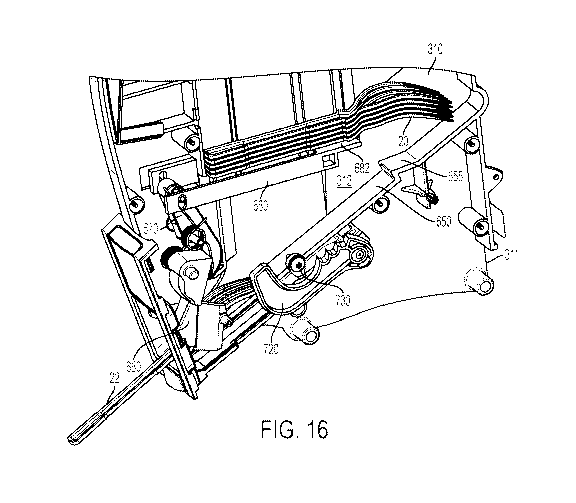
the indicator 2030 relative to the gauge window 172. In an alternative
embodiment that is not
shown, the first gauge arm 2010 and the second gauge arm 2020 can be fixed
together and can
pivot such that movement of the first gauge arm 2010 about the pivot 2012 can
be translated
into movement of the second gauge arm 2020 to move the indicator 2030 relative
to the gauge
window 172.
[0080] The
indicator 2030 can display different quantities of utensils within the stack
2205,
the quantities being visible through the gauge window 172. The indicator 2030
can have
different quantities printed on different parts of the indicator 2030. The
different quantities can
- 18-
CA 03112978 2021-03-16
WO 2020/060683
PCT/US2019/045218
be visible through the gauge window 172 one at a time or multiple quantities
can be displayed
to show that the level is between the quantities displayed. For example, the
indicator 2030
could have "Full" and/or a green color printed on the indicator 2030 that is
visible through the
gauge window 172 when the dispense chassis 150 has more than a certain amount
of utensils
in the utensil stack 2205, more than 50% full, more than 60% full, more than
70 % full more
than 80% full, or more than 90% full; "Half-Full" and/or a yellow color
printed on the indicator
portion that is visible through the gauge window 68 when the dispense chassis
150 has between
certain amounts of utensils 20 in the utensil stack 2205, between 10% full and
90% full,
between 20% full and 80% full, between 30% full and 70% full, between 40% full
and 60%
full; and/or "Empty" and/or a red color printed on the indicator 2030 that is
visible through the
gauge window 172 when the dispense chassis 150 has less than a certain amount
of utensils,
such as less than 5, less than 4, less than 3, less than 2, or none in the
stack 2205. Alternatively,
the colors can be used to indicate how many full stacks of utensils (the
number of utensils in a
full stack of utensil refills can vary) can be added to the dispense chassis
150. For example,
where a full stack of utensil refills is thirty, green may indicate that less
than one full stack of
utensil refills will fit within the dispense chassis 150. Yellow can indicate
that more than one
full stack of utensil refills can be added to the dispense chassis 150, and
red can indicate that
two full stacks of utensil refills can be added to the dispense chassis 150.
[0081] The
first gauge arm 2010 can include any number of extensions or prongs 2040 that
are configured to contact a side of the stack 2205. For example, the first
gauge arm 2020 can
include 1 prong, 2 prongs, 3 prongs, 4 prongs, or 5 prongs disposed along its
length. In one
particular embodiment, the first gauge arm 2010 has two prongs as shown in
Figures 22-24.
The prongs 2040 can be disposed on any suitable position along the length of
the first gauge
arm 2010. If more than two prongs 2040 are used, the spacing between prongs
2040 can be
the same or can vary. Although not shown, each prong 2040 can be moveably
attached to the
first gauge arm 2010 using a clamp or pinch like fastener, so that a prong
2040 can be moved
or adjusted along the length of the first gauge arm 2010 based on patterns of
use.
[0082] The
chassis housing 310 can include a gauge aperture or opening 2045 formed
through an internal wall 310A through which the prong(s) 2040 can extend and
contact a side
of the stack 2205. The gauge aperture or opening 2045 can be a recessed
section or cut away
formed in the internal wall 310A, allowing an adjacent prong 2040 to pass
through. Referring
to the embodiment shown in Figure 22, when the height of the utensil stack
2205 is at or above
- 19 -
CA 03112978 2021-03-16
WO 2020/060683
PCT/US2019/045218
the first or upper gauge opening 2045, the first or upper prong 2040 moves
through the opening
2045 until it contacts the side of the stack 2205. This contact sets the first
gauge arm 2010 at
a first angle about its pivot 2015, which positions the second gauge arm 2020
at a first angle
about its pivot 2025, which positions the indicator 2030 that is visible
through the gauge
window 172. The position of the indicator 2030 corresponds to a quantity of
utensils in the
stack 2205 (i.e. the height of the stack 2205) within the chassis housing 310.
[0083] Figure
23 depicts the dispense chassis 150 having a stack 2205 half-full and empty
of utensils. In this embodiment, the utensil stack 2205 is lower than the
first, upper gauge
opening 2045 and higher than the second, lower gauge opening 2045. The first,
upper prong
2040 extends through its adjacent opening 2045 and the second, lower prong
2040 is blocked
from extending through its adjacent opening 2045 by the stack 2205. Such
positioning sets the
first gauge arm 2010 at a second angle that is rotated relatively
counterclockwise (as shown in
Figure 23) in comparison to the angle of the first gauge arm 2010 in Figure
22. In this position,
the second gauge arm 2020 is rotated about its pivot 2025, moving the
indicator 2030 to show
"Half-Full" or less than half-full through the gauge window 172.
[0084] Figure
24 depicts the stack 2205 in the dispense chassis 150 almost empty. The
utensil stack 2205 is lower than the lower, second gauge opening 2045 so that
the upper and
lower prongs 2040 can both extend through their respective openings 2045 in
the inner wall
310A surrounding the stack 2205. This positions the first gauge arm 2010 at an
angle more
counterclockwise (as shown in Figure 24) in comparison to the positions of the
first gauge arm
2010 in Figures 22 and 23. This in turn, positions the second gauge arm 2020
at a different
angle which positions the indicator 2030 to display "Empty" through the gauge
window 172.
[0085] The
gauge window 172 can have any suitable height, such as about 2 mm, 3 mm, 5
mm or more, and can display colors, numbers, percentages, or any other
indicator to indicate
the number of utensils or stack height within the dispense chassis 150. The
first gauge arm
2010 can swing with gravity and with or without a spring assistance. The
weight and/or the
center of gravity of the first gauge arm 2010 can be adjusted to change how
the utensil stack
gauge 2000 operates. The position and/or the number of the prongs 2040 can be
adjusted to
provide more precise level indicators. Additionally, in an embodiment not
shown, the first
gauge arm 2010 can be located inside the housing wall 310A such that any one
or more of the
- 20 -
CA 03112978 2021-03-16
WO 2020/060683
PCT/US2019/045218
prongs 2040 can directly contact the utensil stack 2205 without passing
through an opening
2045.
[0086] Figure
25 depicts a perspective view of the illustrative utensil dispenser 100
showing a first dispense chassis 150A in a loading position, and a second and
third dispense
chassis 150B, 150C in a dispensing position, according to one or more
embodiments. When
the dispense chassis 150A is in the loading position, utensils can be loaded
into the first
dispense chassis 150A through the loading opening 315. The same is true for
the other dispense
chassis 150B, 150C when time comes to re-load with utensils. Utensils in any
dispense chassis
that is in the dispensing position 330 can be dispensed while any one of the
other dispense
chassis is in a loading position. And as explained in more detail below, any
dispense chassis
150 can be moved between a dispensing position and a loading position while
remaining
connected to the dispenser housing 110. Also as explained below in more
detail, the dispenser
housing 110 can include a mechanism to prevent the dispenser from toppling
over while
loading and re-loading the individual dispense chassis 150.
[0087] Figure
26 depicts an illustrative cut away side views of the lower portion of the
illustrative dispense chassis 150 to better illustrate the dispense chassis in
a dispensing position
2600, and Figure 27 depicts an illustrative cut away side views of the lower
portion of the
illustrative dispense chassis 150 to better illustrate the dispense chassis in
a loading position
2700. Referring to Figures 26 and 27, the utensil dispenser 100 can include a
dispense chassis
support or glide mechanism 3000 which can be connected to the base 120 of the
dispenser
housing 110 for supporting at least one utensil dispense chassis 150.
[0088] The
glide mechanism 3000 can include one or more slots or channels (two are
shown 3100, 3200) for guiding each dispense chassis 150. Each slot 3100, 3200
can resemble
a guide rail or opening and can be configured to retain a prong or pin
appended to a lower
portion of each dispense chassis 150. Each slot 3100, 3200 can be curvilinear
to allow a
dispense chassis to pivot or tilt outward, away from the back of the dispenser
housing 110. The
slope and degree of curvature can be determined based on the size and weight
of the dispense
chassis 150. Likewise, the spacing between the slots 3100, 3200 can be
determined based on
the height of the dispense chassis 150 and the needed clearance from the
dispenser housing
110. The glide mechanism 3000 can support the dispense chassis 150 in a
dispensing position
2600 (Figure 26) and in the loading position 2700 (Figure 27) without having
to remove the
- 21 -
CA 03112978 2021-03-16
WO 2020/060683
PCT/US2019/045218
dispense chassis 150 being loaded from the dispenser. The glide mechanism 3000
also
provides support and guidance to more easily move a dispense chassis 150
between its
dispensing position 2600 and its loading position 2700. The glide mechanism
3000 serves as
a controlled pivot point for each chassis 150.
[0089] To
utilize the glide mechanism 3000, each dispense chassis 150 can include a
first
pin 182 and a second pin 184 that are connected to or integral a lower portion
184 of the
dispense chassis 150. The first pin 182 and/or second pin 186 are configured
to fit and move
within the first and second slots 3100 and 3200 of the glide mechanism 3000.
The first pin 182
and/or second pin 186 can be any rounded cylindrical or tubular shaped
structures. The first
pin 182 and/or second pin 186 can be fixed or stationary. The first pin 182
and/or second pin
186 can also be rollers that can roll within their respective slots 3100,
3200.
[0090] In a
particular configuration, the first slot 3100 can include an arcuate shape and
can guide the first pin 182 in a forward and upward motion as the dispense
chassis 150 is moved
from the dispensing position 2600 to the loading position 2700. The second
slot 3200 can also
have an arcuate shape and can guide the second pin 186 in an arcuate and
forward motion.
Each slot 3100, 3200 can include one or more sidewalls 3130, 3230 to provide a
rail like
containment (Figure 28). Each slot 3100, 3200 can also include a covering or
upper wall 3140,
3240 to further contain the pins 184, 186 of the dispense chassis 150. Each
slot 3100, 3200
can further include an upper opening to allow the dispense chassis 150 to be
removed from the
dispenser housing 110. For example, the first slot 3100 can have a first slot
opening 3150
through which the first pin 182 can escape the first slot 3100 when removing
the dispense
chassis 150 from the glide mechanism 3000. Likewise, the second slot 3200 can
include a
second slot opening 3250 through which the second pin 186 can escape the
second slot 3200
when removing the dispense chassis 150 from the glide mechanism 3000.
[0091] The pins
182 and 186 and/or the slots openings 3150, 3250 can be spaced such that
only one of the pins 182 and 186 can be removed through its respective slot
openings 3150,
3250 at a time. The pins 182 and 186 and/or the slots openings 3150, 3250 can
also be spaced
such that the second slot opening 3250 can be positioned such that the second
pin 186 cannot
be removed from the second slot 3200 unless the first pin 182 is first removed
from its slot
3100. Either or both of these configurations help prevent the dispense chassis
150 from
- 22 -
CA 03112978 2021-03-16
WO 2020/060683
PCT/US2019/045218
inadvertently falling out of the dispenser housing 110 when moving between the
dispensing
position 2600 and the loading position 2700.
[0092] The
first slot 3100 can include a first end and a second end and a crown 3170
therebetween which is relatively higher than the ends. The first pin 182 can
be located at the
first end of the first slot 3100 when the dispense chassis 150 is in the
dispensing position 2600
(Figure 26) and can be located at the second end of the first slot 3100 when
the dispense chassis
150 is in the loading position 2700 (Figure 27). The crown 3170 can bias the
first pin 182
toward the first end or the second end depending on which side of the crown
3170 the first pin
182 is located.
[0093] The
second slot 3200 also includes a first end and a second end with a crown 3270
therebetween. The second pin 186 of the dispense chassis 150 can be located at
the first end
of the second slot 3200 when the dispense chassis 150 is in the dispensing
position 2600 (Figure
2600) and can be located at the second end when the dispense chassis 150 is in
the loading
position 2700 (Figure 27). The crown 3270 can bias the second pin 186 toward
the first end of
the slot 3200 when the second pin 186 is on a first side of the crown 3270 and
can bias the
second pin 186 toward the second end of the slot 3200 when the second pin 186
is on a second
side of the crown 3270. The ends of each slot 3100, 3200 provide a stop for
the dispense
chassis 150 and prevent further movement from the dispensing position 174 and
the loading
position 172.
[0094] Still
referring to Figures 26 and 27, the utensil dispenser 100 can further include
a
chassis interlock assembly 4000 to help prevent the utensil dispenser 100 from
tipping forward
due to having too much weight in front of the base 120. Each glide mechanism
3000 can be
configured with the chassis interlock assembly 4000. The chassis interlock
4000 can include at
least one body or arm 4100 having a contoured lower surface that is configured
to rock on top
of the base 120. The chassis interlock 4000 can also be mechanically joined to
one or more of
the glide mechanisms 3000 to rock together as a single unit.
[0095] Each arm
4100 is configured with an upwardly extending post or lock 4200 that is
configured to enter into the second slot 3200 of the glide mechanism 3000,
preventing the
second pin 186 of every chassis 150 in the dispenser at the time from moving
past. When one
of the dispense chassis 150 is moved to the loading position 2700 (Figure 27),
the chassis
- 23 -
CA 03112978 2021-03-16
WO 2020/060683
PCT/US2019/045218
interlock 4000 tilts forward with the dispense chassis 150, lifting the post
4200 into the back
slot 3200, which locks the other dispense chassis 150 in the dispensing
position 2600. This is
a convenience and a safety feature to keep the utensil dispenser 100 from
tipping forward due
to having too much weight in front of the base 120.
[0096] When all
the dispense chassis 150 in the dispenser housing 110 of the utensil
dispenser 100 are in the dispensing position 2600 (Figure 26), the dispense
chassis interlock
assembly 4000 can be in an unlocked position (Figure 26), and any one of the
dispense chassis
150 can be moved to the loading position 2700 (Figure 27). In the unlocked
position, a first
portion of the interlock arm 4100 can be relatively upward (left side in
Figures 26-28) and the
second portion of the interlock arm 4100 can be relatively lower (right side
of arm 4100 in
Figures 26-28). In the unlocked position, the interlock arm 4100 does not
interfere with the
movement of any of the dispense chassis 150. When one of the dispense chassis
150 is moved
to the loading position 2700 (Figure 27), however, the dispense chassis
interlock 4000 moves
to its locked position (Figure 27) where the post 4200 enters the back slot
3200 and prevents
the other dispense chassis 150 from moving forward. In the locked position,
the first portion
of the interlock arm 4100 toggles downward and the second portion moves up,
causing the post
4200 to interfere with the movement of the second pin 186 of the remaining
dispense chassis
150. Movement of the dispense chassis 150 back to the dispensing position 2600
returns the
dispense chassis interlock 4000 to the unlocked position (Figure 26).
[0097]
Embodiments of the present disclosure further relate to any one or more of the
following paragraphs 1 to 55:
[0098] 1. A
utensil dispenser configured to dispense at least two utensils, comprising: a
housing configured to contain a stack of the utensils therein; an access port
providing an
opening to the housing; a drive mechanism configured to contact and release a
utensil from the
lowermost position of the stack; and an inclined surface located beneath the
stack of utensils,
the inclined surface comprising a positioning mechanism formed thereon.
[0099] 2. The
utensil dispenser according to paragraph 1, wherein the positioning
mechanism is a bump.
[00100] 3. The
utensil dispenser according to paragraph 1 or 2, wherein the positioning
mechanism is a stepped profile.
- 24 -
CA 03112978 2021-03-16
WO 2020/060683
PCT/US2019/045218
[00101] 4. The
utensil dispenser according to any one or more paragraphs 1 to 3, wherein
the positioning mechanism is formed integrally with the inclined surface or
appended thereto.
[00102] 5. The
utensil dispenser according to any one or more paragraphs 1 to 4, wherein
the inclined surface slopes toward the access port.
[00103] 6. The
utensil dispenser according to any one or more paragraphs 1 to 5, wherein
the inclined surface slopes toward the access port at an angle ranging from a
low of about 1, 5,
or 10 degrees to a high of about 50, 60, or 80 degrees.
[00104] 7. The
utensil dispenser according to any one or more paragraphs 1 to 6, further
comprising an actuator that is operably connected to the drive mechanism, the
actuator
configured to move the drive mechanism between a ready position and dispense
position.
[00105] 8. The
utensil dispenser according to paragraph 7, further comprising a prime
mechanism configured to move the actuator and the drive mechanism, the prime
mechanism
comprising a primer handle mechanically linked to a ratchet having one or more
teeth for
engaging a pawl that is disposed on an inner wall of the housing.
[00106] 9. The
utensil dispenser according to paragraph 8, wherein the actuator comprises
outwardly extending posts configured to engage the ratchet, thereby moving the
actuator as the
primer handle is extended from the housing.
[00107] 10. The
utensil dispenser according to any one or more paragraphs 7 to 9, wherein
the actuator is disposed above a lower end of the inclined surface.
[00108] 11. A
utensil dispenser configured to dispense at least two utensils, comprising: a
housing configured to contain a stack of the utensils therein; an access port
providing an
opening to the housing; a drive mechanism configured to contact and release a
utensil from the
lowermost position of the stack; an inclined surface located beneath the stack
of utensils; and
an actuator that is operably connected to the drive mechanism, the actuator
configured to move
the drive mechanism between a ready position and dispense position, wherein
the actuator
comprises: a body that is pivotably mounted to the housing, an opening formed
through a lower
portion of the body, and at least one arm located proximate the opening and
extending from the
body toward the access port.
- 25 -
CA 03112978 2021-03-16
WO 2020/060683
PCT/US2019/045218
[00109] 12. The
utensil dispenser according to paragraph 11, wherein the at least one arm
comprises two generally parallel arms extending from the body toward the
access port.
[00110] 13. The
utensil dispenser according to paragraphs 11 or 12, wherein the at least one
arm is configured to exert a downward force on a utensil disposed on the
inclined surface,
preventing the utensil from moving back into the housing.
[00111] 14. The
utensil dispenser according to any one or more paragraphs 11 to 13,
wherein the actuator comprises a contoured surface for engaging a mating
contoured surface
on the drive mechanism.
[00112] 15. The
utensil dispenser according to paragraph 14, wherein the contoured
surfaces are cam surfaces.
[00113] 16. The
utensil dispenser according to any one or more paragraphs 11 to 15,
wherein the inclined surface slopes toward the access port.
[00114] 17. The
utensil dispenser according to any one or more paragraphs 11 to 16,
wherein the inclined surface slopes toward the access port at an angle ranging
from a low of
about 1, 5, or 10 degrees to a high of about 50, 60, or 80 degrees.
[00115] 18. The
utensil dispenser according to any one or more paragraphs 11 to 17, further
comprising a prime mechanism configured to move the actuator and the drive
mechanism, the
prime mechanism comprising a primer handle mechanically linked to a ratchet
having one or
more teeth for engaging a pawl that is disposed on an inner wall of the
housing.
[00116] 19. The
utensil dispenser according to paragraph 18, wherein the actuator further
comprises outwardly extending posts configured to engage the ratchet, thereby
moving the
actuator as the primer handle is extended from the housing.
[00117] 20. The
utensil dispenser according to paragraphs 18 or 19, wherein the actuator is
disposed above a lower end of the inclined surface.
[00118] 21. A
utensil dispenser configured to dispense at least two utensils, comprising: a
housing configured to contain a stack of the utensils therein, wherein the
stack of the utensils
comprises at least one utensil in addition to a next utensil; an access port
providing an opening
to the housing; a drive mechanism configured to contact the next utensil; an
actuator that is
- 26 -
CA 03112978 2021-03-16
WO 2020/060683
PCT/US2019/045218
operably connected to the drive mechanism and configured to move the drive
mechanism
where the drive mechanism pushes the next utensil in the stack causing the
next utensil to
release from the stack of the utensils; and a prime mechanism configured to
move the actuator
and the drive mechanism between a ready position and a dispense position, the
prime
mechanism comprising a primer handle mechanically linked to a ratchet having
one or more
teeth for engaging a pawl that is disposed on an inner wall of the housing.
[00119] 22. The
utensil dispenser according to paragraph 21, wherein the prime mechanism
is configured to move between an extended position and a rest position,
whereby the drive
mechanism is moved to its ready position when the prime mechanism is moved to
the extended
position and the drive mechanism is moved to its dispense position when the
prime mechanism
is moved to the rest position.
[00120] 23. The
utensil dispenser according to paragraphs 21 or 22, further comprising a
return spring configured to bias the prime mechanism toward the rest position.
[00121] 24. The
utensil dispenser according to any one or more paragraphs 21 to 23,
wherein the prime mechanism is configured to actuate the drive mechanism when
the primer
handle is pulled away from the housing.
[00122] 25. The
utensil dispenser according to any one or more paragraphs 21 to 24,
wherein the ratchet is operatively connected to the actuator to move the
actuator thereby
moving the drive mechanism.
[00123] 26. The
utensil dispenser according to any one or more paragraphs 21 to 25,
wherein the actuator comprises outwardly extending posts configured to engage
the ratchet,
thereby moving the actuator as the primer handle and ratchet are extended from
the housing.
[00124] 27. The
utensil dispenser according to any one or more paragraphs 21 to 26,
wherein the primer handle is accessible outside the housing and configured to
slide away from
the access port, whereby movement of the primer handle drives the actuator and
initiates the
release of the next utensil from the stack.
[00125] 28. The
utensil dispenser according to any one or more paragraphs 21 to 27,
wherein the ratchet comprises a push surface adapted to engage one or more
outwardly
extending posts appended to the actuator.
- 27 -
CA 03112978 2021-03-16
WO 2020/060683
PCT/US2019/045218
[00126] 29. The
utensil dispenser according to any one or more paragraphs 21 to 28,
wherein the ratchet comprises a dwell surface located between the push surface
and the teeth,
the dwell surface allows the pawl to reset as the primer handle returns into
the housing.
[00127] 30. The
utensil dispenser according to any one or more paragraphs 21 to 29,
wherein the prime mechanism comprises two ratchets, one opposite the other,
whereby the
utensil is able to pass between the ratchets.
[00128] 31. A
utensil dispenser configured to dispense at least two utensils, comprising: a
housing configured to contain a stack of the utensils therein, wherein the
stack of the utensils
comprises at least one utensil in addition to a next utensil and each utensil
comprises at least
one contoured projection extending outwardly therefrom; a front pedestal
disposed inside the
housing, the front pedestal configured to support at least one of the at least
one contoured
projections extending outwardly from the next utensil; and a moveable member
disposed
within the housing, the moveable member having an engaging section capable of
engaging the
contoured projection extending outwardly from the next utensil, the moveable
member
configured to move from a ready position to a dispense position.
[00129] 32. The
dispenser according to paragraph 31, further comprising a rear pedestal
disposed inside the housing, the rear pedestal configured to support one end
of the next utensil.
[00130] 33. The
dispenser according to paragraphs 31 or 32, wherein the moveable member
is substantially parallel with the next utensil.
[00131] 34. The
dispenser according to any one or more paragraphs 31 to 33, wherein the
contoured projection on each utensil has a tapered outer surface.
[00132] 35. The
dispenser according to any one or more paragraphs 31 to 34, wherein the
contoured projection fits within the engaging section of the moveable member.
[00133] 36. The
dispenser according to any one or more paragraphs 31 to 35, wherein the
moveable member is configured to move about the contoured projection, allowing
the
contoured projection of the next utensil to at least partially reside within
the engaging section
of the moveable bar.
- 28 -
CA 03112978 2021-03-16
WO 2020/060683
PCT/US2019/045218
[00134] 37. The
dispenser according to paragraph 36, wherein the moveable member
comprises at least one extension arm and the engaging section of the moveable
member is
disposed on at least one of the at least one extension arms, the at least one
extension arm
configured to flex outwardly when sliding about the contoured projection.
[00135] 38. The
dispenser according to any one or more paragraphs 31 to 37, wherein the
moveable member comprises at least one extension arm and the engaging section
of the
moveable member is disposed on at least one of the at least one extension
arms, the engaging
section configured to move beneath the contoured projection.
[00136] 39. The
dispenser according to any one or more paragraphs 31 to 38, wherein the
moveable member comprises at least one extension arm and the engaging section
of the
moveable member is disposed on at least one of the at least one extension
arms, the engaging
section configured to move above the contoured projection.
[00137] 40. A
utensil dispenser configured to dispense at least two utensils, comprising: a
housing configured to contain a stack of the utensils therein, wherein the
stack of the utensils
comprises at least one utensil in addition to a next utensil and each utensil
comprises at least
one contoured projection extending outwardly therefrom; a front pedestal
disposed inside the
housing, the front pedestal configured to support the at least one contoured
projection
extending outwardly from the next utensil; and a moveable member disposed
within the
housing and configured to move from a ready position to a dispense position,
the moveable
member comprising at least one extension arm configured with at least one
engaging section,
wherein the engaging section is capable of receiving the contoured projection
extending
outwardly from the next utensil.
[00138] 41. The
dispenser according to paragraph 40, wherein the engaging section of the
moveable member comprises a slot, notch or area of reduced wall thickness in
the extension
arm.
[00139] 42. The
dispenser according to paragraphs 40 or 41, wherein the moveable member
comprise two extension arms situated to flank opposing longitudinal sides of
the next utensil.
[00140] 43. The
dispenser according to any one or more paragraphs 40 to 42, wherein the
engaging section of the moveable member is configured to move relative to the
contoured
- 29 -
CA 03112978 2021-03-16
WO 2020/060683
PCT/US2019/045218
projection, allowing the contoured projection of the next utensil to at least
partially reside
within the engaging section of the moveable bar.
[00141] 44. The
dispenser according to any one or more paragraphs 40 to 43, wherein the
extension arm of the moveable member is configured to flex outwardly as the
engaging section
of the moveable member move about the contoured projection.
[00142] 45. The
dispenser according to any one or more paragraphs 40 to 44, wherein the
engaging section of the moveable member is configured to move beneath the
contoured
projection.
[00143] 46. The
dispenser according to any one or more paragraphs 40 to 45, wherein the
engaging section of the moveable member is configured to move above the
contoured
projection.
[00144] 47. A
utensil dispenser configured to dispense at least two utensils, comprising: a
housing configured to contain a stack of the utensils therein, wherein the
stack of the utensils
comprises at least one utensil in addition to a next utensil and each utensil
comprises at least
one contoured projection extending outwardly therefrom; a front pedestal
disposed inside the
housing, the front pedestal configured to support the at least one contoured
projection
extending outwardly from the next utensil; a rear pedestal disposed inside the
housing, the rear
pedestal configured to support a handle end of the next utensil; a dispensing
mechanism
disposed within the housing, the dispensing mechanism comprising at least two
engaging
surfaces configured to move back and forth; a moveable member disposed within
the housing
and configured to move from a ready position to a dispense position due to the
back and forth
movement of the dispensing mechanism, the moveable member having at least one
extension
arm extending away from the rear pedestal and configured with at least one
engaging section
proximate a distal end thereof, wherein the engaging section is capable of
receiving at least a
portion of the contoured projection extending outwardly from the next utensil.
[00145] 48. The
dispenser according to paragraph 47, wherein the extension arm of the
moveable member is configured to flex outwardly as the engaging section of the
moveable
member moves about the contoured projection.
- 30 -
CA 03112978 2021-03-16
WO 2020/060683
PCT/US2019/045218
[00146] 49. The
dispenser according to paragraphs 47 or 48, wherein the engaging section
of the moveable member is configured to move beneath the contoured projection.
[00147] 50. The
dispenser according to any one or more paragraphs 47 to 49, wherein the
engaging section of the moveable member is configured to move above the
contoured
projection.
[00148] 51. A
method for dispensing one or more utensils from a dispenser, comprising:
pulling a handle end of a utensil extending from a housing configured to
contain a stack of
utensils therein, each utensil comprising at least one contoured projection
extending outwardly
therefrom and supported on a front pedestal disposed inside the housing;
triggering a movement
of a first portion of a dispensing mechanism to move an extension member
within the housing,
the extension member having an engaging section capable of receiving the
contoured
projection extending outwardly from a utensil located at a bottom of the
stack, wherein
generally linear movement of the extension member releases the utensil from
the bottom of the
stack; and retaining the released utensil within the housing using a second
portion of the
dispensing mechanism, the second portion located beneath the first portion and
comprising an
opening to allow the handle end of the released utensil to pass through and
extend outside the
housing.
[00149] 52. The
method according to paragraph 51, wherein the engaging section of the
extension member is configured to flex outwardly as the extension member moves
about the
contoured projection.
[00150] 53. The
method according to paragraphs 51 or 52, wherein the engaging section of
the extension member is configured to move beneath the contoured projection.
[00151] 54. The
method according to any one or more paragraphs 51 to 53, wherein the
engaging section of the extension member is configured to move above the
contoured
projection.
[00152] 55. The
method according to any one or more paragraphs 51 to 54, wherein the
moveable member comprise two extension arms configured to flank opposing
longitudinal
sides of the utensil located at the bottom of the stack.
-31 -
CA 03112978 2021-03-16
WO 2020/060683
PCT/US2019/045218
[00153] Certain
embodiments and features have been described using a set of numerical
upper limits and a set of numerical lower limits. It should be appreciated
that ranges including
the combination of any two values, e.g., the combination of any lower value
with any upper
value, the combination of any two lower values, and/or the combination of any
two upper
values are contemplated unless otherwise indicated. Certain lower limits,
upper limits and
ranges appear in one or more claims below. All numerical values are "about" or
"approximately" the indicated value, and take into account experimental error
and variations
that would be expected by a person having ordinary skill in the art.
[00154] Various
terms have been defined above. To the extent a term used in a claim is not
defined above, it should be given the broadest definition persons in the
pertinent art have given
that term as reflected in at least one printed publication or issued patent.
Furthermore, all
patents, test procedures, and other documents cited in this application are
fully incorporated by
reference to the extent such disclosure is not inconsistent with this
application and for all
jurisdictions in which such incorporation is permitted.
[00155] While
the foregoing is directed to embodiments of the present invention, other and
further embodiments of the invention may be devised without departing from the
basic scope
thereof, and the scope thereof is determined by the claims that follow.
- 32 -