Note : Les descriptions sont présentées dans la langue officielle dans laquelle elles ont été soumises.
CA 03113555 2021-03-19
- 1 -
Plastic container
The invention relates to a container made of thermoplastic material for the
storage and
transport of liquid or free-flowing contents, which container is produced in a
blow molding
process and, at a container opening in the top of the container, is provided
with a welded-on
bung connector part prefabricated in an injection molding process and having
internal
threads for closing the container opening which are provided at the upper end.
Usually, blow-molded plastic containers of this type are drums with a handling
ring, coming
in drum sizes from 120 liters to 250 liters. The most common are drums which
have a
storage capacity of 220 liters, but there are also others on the market. Other
plastic
containers, such as e.g. 30 or 60 liter canisters with bung fitting closures
are likewise
known. All of these plastic containers are used for the storage and transport
of liquid or free-
flowing filling contents and are usually equipped with a larger 2-inch and a
smaller %-inch
bung opening, the larger bung serving for filling and removing the filling
material and the
smaller bung serving as a ventilation bung during the filling and removal
operation.
In industrial chemistry, large quantities of plastic containers of this type
are generally filled
virtually exclusively in automatic filling installations at the end of the
process for preparing
chemical liquids. In this respect, the plastic container is positioned such
that the bung
connectors are always precisely oriented and automatic unscrewing devices can
grasp and
unscrew the bung fittings. A filling lance then moves into the larger 2-inch
bung opening and
the liquid contents are pumped into the container at a high filling pressure.
After the filling
operation has been completed, the bung fittings are screwed back into the
filling/removal
connector and the ventilation connector by the automatic unscrewing machine.
Problem:
Plastic containers with bung fittings are produced in large numbers worldwide,
for the most
part in a blow molding process. In the process, the hollow bodies are inflated
from an
extruded tubular preform between two blow mold halves, which can be moved
together
horizontally, under the action of injected compressed air to afford their
final form. When the
two blow mold halves move together, the tubular preform is squeezed out and
welded at the
Date Recue/Date Received 2021-03-19
CA 03113555 2021-03-19
- 2 -
top and bottom. Normally, the bottom of the container body is formed in the
top of the blow
mold and the top of the container body with the bung openings is formed in the
bottom of
the blow mold. The length of the flash seam and the exact position of the bung
connectors
can be set by means of movable expanding and blowing mandrels. The shaping of
the
bottom of the container body in the top of the blow mold is comparatively
simple because
the bottom, as a standing surface for the container body, should have a form
as flat and
planar as possible, if necessary with stiffening beads, while the forming of
the top of the
container body, with an handling ring encircling the outer circumference, with
a convex or
higher middle part and with two diametrically oppositely situated bung
connectors which are
placed deeper in bung hollows, has a considerably more difficult
configuration. The
particular art of blow molding technology consists in the ingenious control of
the wall
thickness of the extruded tubular preform, since there should be the same wall
thickness as
far as possible everywhere on the finished container body. This is not
entirely possible in
terms of process technology, since there is always a thickening of material at
both ends of
the upper and lower flash seam of the tubular preform. In the bottom of the
container body,
the two thickenings of material are drawn as flat as possible. The resultant
thickenings of
material in the top of the container body are used to form two bung
connectors, having
internal threads, on two blowing mandrels arranged below the blow mold in the
top of the
container body. The two bung connectors are each arranged in the top in a
manner
recessed in a bung hollow or a bung housing. The handling ring encircling the
outer
circumference of the top is molded on from the plastic material of the tubular
preform during
the blow molding operation by means of vertically displacable mold slides.
After the blow
molding operation has ended, before the finished container body is removed
from the blow
mold, the blowing mandrels are unscrewed from the molded-on bung connectors
having
internal threads. While the vertical container wall and the bottom of the
hollow body are
cooled comparatively quickly, the components such as the handling ring and
bung
connector, which entail increased use of material, understandably require a
longer cooling
time to room temperature. Since the same cooling conditions are not present in
all
directions on the bung connectors due to thickenings of material on the one
side and also
due to a flash seam, which runs in on one side, on the other side and the
proximity of the
solid handling ring, this can lead to material distortion and deviations in
the geometric
dimensions as a result of the blow molding, possibly with subsequent cooling
under internal
pressure.
Date Recue/Date Received 2021-03-19
CA 03113555 2021-03-19
- 3 -
Here, it is possible that e.g. the bung openings in the bung connectors become
oval in
shape, with the result that the seal of a screwed-in bung fitting on the seal
seat can no
longer provide a complete sealing action and the bung closure becomes leaky,
in particular
when a container filled with liquid contents falls over. In addition,
disruptive film-like plastic
appendages which have a detrimental effect on the seat of the screwed-in bung
fitting can
form on the flash seam which runs in on one side.
On the other hand, the bung connectors themselves can warp into a slight
inclination, which
later can lead to problems in the automatic filling installations when
containers of this type
are being filled if e.g. the automatic unscrewing machine for the bung fitting
cannot engage
exactly into the upper recesses in the bung fitting for the screw head tool or
the vertically
descending filling lances for pressure filling cannot precisely move into the
bung openings of
the bung connectors. Faults in automatic industrial-chemical filling
installations that are
caused by this cost time and money and result in dissatisfied customers.
Prior art:
The document EP 0 515 390 B1 discloses a blow-molded bung drum made of
thermoplastic
material, in which a bung connector prefabricated in an injection molding
process is welded
into the top of the drum body. In this respect, the bung connector has a pipe
piece which
has an internal thread and protrudes to some extent into the drum body. This
structure was
selected because the bung housing has a very flat form and the upper edge of
the bung
connector with the screwed-in bung fitting does not protrude beyond the top,
but should
terminate flush therewith. In order that there is a sufficient number of
thread turns for a
secure seat of the screwed-in bung fitting, the bung connector pipe piece is
displaced here
to some extent into the drum interior. In order nevertheless to allow good
residual emptying,
the bung connector pipe piece is provided with a cutout or aperture on the
side facing
outward toward the handling ring, with the result that the last drops of
residual liquid can
flow out from the drum interior. The bung connector pipe piece was welded in
by deposition
welding with the addition of molten plastic material. In the absence of
corresponding welding
surfaces, the bung connector pipe piece cannot be welded in using a mirror
welding
process.
Date Recue/Date Received 2021-03-19
CA 03113555 2021-03-19
- 4 -
In the publication WO 2018/054 527 Al, it appears in the drawings of the
figures that a
whole bung hollow area, including bung connectors, is welded into the top of a
drum with a
handling ring, although nothing at all is mentioned in the description because
the underlying
inventive concept relates specifically to the use of a thin-walled inliner.
From the prior art, the use of the mirror welding process for plastic
containers is known from
numerous prior publications, such as e.g. from
EP 0 721 892 Al. Said document describes that, for a bung drum, the top of the
drum,
including the carrying and transport ring, bung connectors and attachment
elements, is
prefabricated in an injection molding process and then welded onto a blow-
molded drum
body blank. In another embodiment, a plastic drum of this type can of course
also be
welded together from a top and a bottom which are prefabricated in an
injection molding
process with an extruded cylindrical drum body blank composed of three parts.
Object:
The present invention is based on the object of rectifying the above-mentioned
disadvantages
of the prior art and of proposing an option for the optimal welding in
- preferably in a mirror welding process - of bung connectors or bung
connector parts,
which are prefabricated separately in an injection molding process and have
internal
threads, onto plastic containers, such as drums, canisters and inner
containers for pallet
containers, produced in a blow molding process in such a way that, when using
blow-
molded plastic containers in existing filling and pumping installations,
container-related
faults no longer occur or can be minimized to the greatest possible extent.
Solution:
This object is achieved by the special features of patent claim 1. The
features in the
dependent claims describe further advantageous configuration options of the
blow-molded
container according to the invention having welded-on bung connector parts
prefabricated in
Date Recue/Date Received 2021-03-19
CA 03113555 2021-03-19
- 5 -
an injection molding process. The proposed technical teaching conveys in a
simple manner
how the disadvantages of known blow-molded plastic containers can be overcome;
this is
achieved in design terms by the following features:
- provided on the container side is an annular welding surface with a
circular inner edge
and a circular outer edge,
- the bung connector part prefabricated in an injection molding process is
designed as a
solid threaded welding head with an internal thread and
- has a corresponding annular welding surface with a circular inner edge
and a circular
outer edge, and
- the two annular welding surfaces are materially bonded to one another in
a fixed and
non-detachable manner.
The spaced-apart inner and outer edges of the welding surfaces
- viewed in the vertical direction - bring about a planar extent of the
annular welding
surfaces. The width of the welding surfaces is between 3 mm and 15 mm,
preferably
approx. 5 mm, viewed running in the radial direction or obliquely, and
therefore here in
particular the mirror welding process is particularly suitable. The flatter
the welding surfaces
are oriented on the container side and on the threaded welding head, the wider
is the extent
to which they overlap. The steeper the welding surfaces are oriented on the
container side
and on the threaded welding head, the less is the extent to which they
overlap, until
ultimately there is no longer any overlap in the case of vertically oriented
welding surfaces
and welding by the mirror welding process cannot be performed. In the case of
vertically
oriented welding surfaces of this type, the bung connectors and the top of the
container are
usually welded by deposition welding with the addition of molten plastic
material.
The solid threaded welding head, prefabricated in an injection molding
process, prevents
the bung opening and the sealing seat for the bung fitting from possibly
becoming oval in
shape and comprises precisely formed thread turns with sharp thread flanks. In
the region
of its largest diameter, the solid threaded welding head has a thickening or
accumulation of
plastic material with a wall thickness, of approx. 6 - 8 mm, that is virtually
twice as thick in
comparison with the wall thickness of the top of the container, which has a
wall thickness of
approx. 3 -4 mm.
Date Recue/Date Received 2021-03-19
CA 03113555 2021-03-19
- 6 -
In principle, the threaded welding head could be materially bonded to the top
of the plastic
container in various ways, e.g. by gluing, wetting or the like. In the present
invention, the
material bond should preferably be effected in the known mirror welding
process which is
particularly suitable for this, the two welding surfaces being partially
melted by applying
correspondingly shaped, heated welding elements and, after removing the
welding
elements, being firmly pressed against one other and connected or welded to
one another
in a non-detachable manner.
One configuration of the invention provides that the annular welding surface
on the
container side and the corresponding annular welding surface on the solid
threaded welding
head are formed as running substantially obliquely in three dimensions. In
this respect, the
opening, which is enclosed by the annular welding surface, in the top of the
container has
an almost trapezoidal form when viewed in cross section. Expressed
differently, when the
container is positioned upright with the openings upward, the opening, which
is enclosed by
the annular welding surface on the container side, in the top of the container
constitutes an
upside-down form of a conical section with base upward and tip downward.
With normal upright positioning of the container, the outer edges of the two
welding surfaces
lying one on top of the another are advantageously arranged higher than the
inner edges of
the two welding surfaces. This design configuration makes it possible to
better center and
vertically orient the solid threaded welding head when it is being welded in.
In a modified embodiment of the invention, the annular welding surface on the
container
side has a substantially concave form and the annular welding surface on the
threaded
welding head has a substantially convex form. The adaptation of the two three-
dimensional
annular welding surfaces to one another that is carried out enables better
centering and
orientation of the threaded welding head when it is being welded into the top
of the
container.
A preferred modification of the invention provides that the outer side of the
threaded welding
head has a dome-like form at least in the region of its annular welding
surface and the
annular welding surface on the container side has a corresponding negative
dome-like form.
The dome-shaped form of the annular welding surfaces of the two parts to be
welded
Date Recue/Date Received 2021-03-19
CA 03113555 2021-03-19
- 7 -
makes it possible to most effectively compensate unevennesses and inclinations
in the base
region of the bung housing or when the top of the container is slightly
convex, and therefore
a precise vertical orientation of the welded-in threaded welding head is
achieved, as a result
of which existing problems and faults caused thereby when using blow-molded
plastic
containers in existing filling and pumping installations no longer occur.
In a very particularly preferred design configuration, the outer side of the
threaded welding
head has an almost entirely dome-like form. The threaded welding head has the
form of a
spherical segment, also referred to as spherical disk, and is a part of a full
sphere that is cut
by two parallel planes. The curved surface part is referred to as spherical
zone and
constitutes the dome-like outer side of the threaded welding head.
The specific form of a spherical dome allows optimal welding-in conditions and
a solid
configuration of the threaded welding head in a decorative design. In the case
of blow-
molded bung drums, the plastic material is usually colored blue. The separate
manufacture
of the threaded welding heads in an injection molding process makes it
possible to choose
another color for the welded-on threaded welding heads. As an indication of
certain
contents, the prefabricated threaded welding heads can comprise e.g. the color
red for
hazardous goods containers, the color green for plastic containers with
environmentally
friendly contents or the color yellow for food-safe plastic containers.
The compact spherical dome-like configuration of the solid threaded welding
head
particularly makes it possible that the annular welding surface on the
container side is
formed virtually without a connector and directly in the bung opening in the
top of the
container on a formed-on bead ring. In this way, e.g. the depression of a bung
housing or of
a bung hollow in the top of the plastic container can be kept particularly
flat, as a result of
which improved residual emptying of the plastic container can be realized. The
direct
welding of a threaded welding head without a connector and virtually directly
into a bung
opening in the top of a container is suitable in particular for 1000 liter
plastic inner
containers of pallet containers that do not have a separate bung housing for
the bung
opening, but only a deeper middle region of the top of the inner container.
Date Recue/Date Received 2021-03-19
CA 03113555 2021-03-19
- 8 -
In one design configuration of the invention, preferably in the case of bung
drums and
canisters, the annular welding surface on the container side is formed on the
upper edge of
a short welded bung connector enclosing the bung opening in the top of the
container. The
welded bung connectors for the conventional %-inch, 2-inch and 3-inch bung
closures are
expediently formed as standard welded bung connectors with a respectively
identical
contour, regardless of the container size. In this respect, "identical
contour" means the same
dimensions in terms of length and diameter.
In that case, the drum bodies or drums having a handling ring can also be
produced as
universal drum bodies with standard welded bung connectors of reduced wall
thickness, as
it were, in the blow mold for the various bung closures without frequently
interchanging the
blowing mandrels. By reducing conversion times and shortening cooling times, a
significant
increase in the number of items is achieved.
Freely selectable, prefabricated standard threaded welding heads with all
conventional
thread forms can then be welded into the standard welded bung connector.
If drums with a handling ring are used in Europe, the one bung is usually
designed as a 2-
inch filling and emptying bung and the other bung as a %-inch aeration and
ventilation bung,
each having a coarse thread, while drums with a handling ring which are used
primarily in
the American or Asian market are equipped with two 2-inch bungs, in that case
the one
bung being equipped with a coarse thread and the other bung being equipped
with a fine
thread.
Numerous advantages can be achieved by the present invention:
- it is possible to insert a thin-walled inliner into the universal drum
body and radially weld
in the thin-walled inliner connector in the cylindrical region of the standard
welded bung
connector and only then to fit or weld the threaded welding head having any
desired
thread onto the standard welded bung connector;
- the manufacture of the universal drum body with the two standard welded
bung
connectorscan be optimized in terms of blow molding technology, e.g. by
shortening the
Date Recue/Date Received 2021-03-19
CA 03113555 2021-03-19
- 9 -
cycle times, since the intensive cooling of the usual threaded flanges is
dispensed with
and the unscrewing time for the threaded blowing mandrels is also omitted;
- the wall thickness of the tubular preform can be better controlled, since
the plastic
material is no longer required to form the thread;
- a change of tools (different shells and blowing mandrels) when changing
from one bung
connector geometry to another bung connector geometry (coarse thread - fine
thread) is
dispensed with;
- the tolerances of the threaded flanges can be improved or minimized, this
being
important in particular in the case of the American fine thread (NPS 2-inch);
- the ovality of the threaded opening in the threaded welding heads is
eliminated;
- possible inclination of the standard welded bung connectors with respect
to the top of
the container can be compensated by the dome geometry of the threaded welding
heads during the welding-on operation;
- the tolerances of the external geometry for the sealing caps to be fitted
on can be set
significantly closer;
- threaded welding heads with an individually colored configuration allow a
visual
distinction to be made from the usual standard blue drums with a handling
ring;
- planar welding surfaces can also be implemented as alternative welding
geometries
with the highest degree of simplicity.
The invention is explained and described in more detail below with reference
to exemplary
embodiments shown schematically in the drawings, in which:
figure 1 shows a perspective view of a blow-molded plastic container
according to the
invention in the form of a bung drum with welded-in threaded welding flanges,
figure 2 shows a cross-sectional view of a threaded welding head according to
the
invention,
figure 3 shows a partial cross-sectional view through a welded-in threaded
welding
flange,
figure 4 shows another partial cross-sectional view through a welded-in
threaded welding
head,
figure 5 shows a further partial cross-sectional view through a welded-in
threaded
welding head,
Date Recue/Date Received 2021-03-19
CA 03113555 2021-03-19
- 10 -
figure 6 shows a partial cross-sectional view of another embodiment of a
welded-in
threaded welding head.
Figure 1 illustrates a bung drum made of thermoplastic material and denoted by
the
reference numeral 10 as a preferred exemplary embodiment of a blow-molded
plastic
container. Bung drums with an upper handling ring are available in a variety
of drum sizes
with a filling volume of from 30 liters to 300 liters. The most common are 220
liter bung
drums with two bung closures in the top of the drum. According to the
invention, the bung
closures are each provided with a welded-in threaded welding head 12,
prefabricated in an
injection molding process, into which the customary bung fittings are screwed
in order to
close the bung opening 28 in a gas- and liquid-tight manner.
An embodiment according to the present invention of a threaded welding head is
illustrated
in figure 2. The threaded welding heads 12 according to the invention can be
designed in
various sizes. Preferred sizes are %-inch, 2-inch and 3-inch threaded welding
heads. The
threaded welding heads 12 according to the invention can furthermore be
provided with
various types of thread, specifically either with a coarse thread and a seal
seat arranged
below the thread or with a fine thread and a seal seat arranged above the
thread.
2-inch threaded welding heads can moreover be formed with a customary BCS 70 x
6
thread.
The upper bung connector part, prefabricated in an injection molding process,
is in the form
of a solid threaded welding head 12 such as a spherical-dome ring element with
a central
bore for receiving an internal thread and a wall part enclosing the bore and
having a wall
thickness thickened by material accumulation.
The solid threaded welding head 12 with an internal thread 20 has an annular
welding
surface 22, which has a circular inner edge 24 and a circular outer edge 26,
on the
circumference. The outer side of the threaded welding head 12 can have a dome-
like form
on the circumference at least in the region of its annular welding surface 22.
In a preferred
embodiment, the outer side of the threaded welding head 12 has an almost
entirely dome-
like form. The spherical dome form of the threaded welding head 12 is
represented by the
circle indicated by a dashed line in figure 2 and has the shape of a three-
dimensional
Date Recue/Date Received 2021-03-19
CA 03113555 2021-03-19
-11 -
spherical segment with a uniformly curved outer spherical zone as the dome-
like outer side
of the threaded welding flange.
The height of the annular welding surface 22 is defined by the arrow HK.
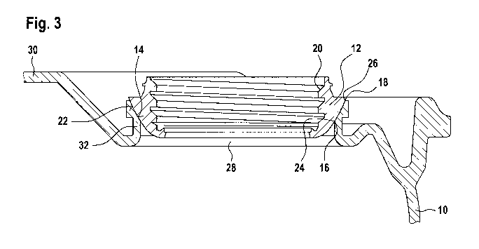
Figure 3 illustrates a threaded welding head 12 in the installed state in the
case of a bung
drum 10 with a circumferential handling ring. The bung opening 28 arranged in
a bung
hollow of the top 30 is enclosed by a welded bung connector 32. Formed on the
upper edge
of the welded bung connector 32 is an annular welding surface 14 with a
negative dome-like
contour, which has a circular inner edge 16 at the bottom and a circular outer
edge 18 at the
top. The welded-in threaded welding head 12 with a dome-like outer side
accordingly
comprises the annular welding surface 22 with a circular inner edge 24 and a
circular outer
edge 26. In this way, with normal upright positioning of the bung drum 10, the
outer edges
18,26 of the two welding surfaces 14,22 lying one on top of the another are
thus arranged
higher than the inner edges 16,24 of the two welding surfaces 14,22. The
mirror welding
process, which is particularly suitable, is used for the welding operation on
account of the
comparatively large width of the welding surfaces, which is between 3 mm and
15 mm,
preferably approx. 5 mm, running in the radial direction or obliquely. After
the welding
operation, the two annular welding surfaces 14 and 22 are connected or welded
to one
another in a materially bonded, fixed and non-detachable manner.
Figure 4 illustrates the upper region of a bung drum 10, in the case of which,
in an
exaggerated form in the drawing, the top 30 is strongly upwardly convex or
bulged outward -
e.g. by virtue of subsequent cooling possibly under an excessively high
internal pressure.
As a result, the welded bung connector 32 is slightly warped and outwardly
deflected here.
The dome shape of the welded bung connector 32 also makes it possible for the
internal
thread 20 of the bung opening 28 to be oriented vertically even if the top 30
is "crooked".
It is possible that, as a result of the slower cooling of thick locations, in
particular along the
flash seams of a plastic hollow body removed from the blow mold after the
operation of
shaping by blow molding, stresses internal to the material cause distortion,
which can lower
the top of the hollow body inward or downward. One such case is illustrated in
figure 5 in
an exaggerated form in the drawing, in which, in the case of the bung drum 10,
the top 30
has lowered downward and the welded bung connector 32 is inclined toward the
middle of
Date Recue/Date Received 2021-03-19
CA 03113555 2021-03-19
- 12 -
the top 30. The vertical orientation of the dome-like threaded welding head 12
compensates
the inclination of the welded bung connector 32, with the result that the
internal thread 20 in
the bung opening 28 with a screwed-in bung fitting is precisely oriented for
the use of
automatic screwing machines and filling lances in automatic filling
installations and
problems no longer arise.
In the context of the present invention, in a simple embodiment, the annular
welding surface
14 on the container side and the corresponding annular welding surface 22 on
the solid
threaded welding head 12 can be formed as running obliquely in three
dimensions. In that
case, the bung opening 28 enclosed by the annular welding surface 14 in the
top 30 of the
bung drum 10 has an almost trapezoidal form when viewed in cross section. In a
modified
form, it is also possible for the annular welding surface 14 on the container
side to be
formed as concave and the annular welding surface 22 on the threaded welding
head 12 to
be formed as convex.
In a particularly preferred embodiment, the annular welding surface 14 on the
container side
is arranged on the upper, somewhat widened edge of the weld bung connector 32
of
shortened form which encloses the container opening 28 in the top 30 of the
container 10.
In this respect, the welded bung connector 32 is formed respectively as a
standard welded
bung connector with the same diameter of e.g. 65 mm for the conventional %-
inch, 2-inch
and 3-inch bung closures, regardless of the container size, onto which welded
bung
connector a correspondingly adapted standard threaded welding head 12 with
likewise
always the same diameter of e.g. 70 mm is welded, the opening 36 of which,
which has an
internal thread, can be freely selected for the use of the conventional %-
inch, 2-inch and 3-
inch bung closures.
A frequently used threaded welding head is designed for a bung closure or bung
fitting BSC
70 x 6 for steel sealing caps.
It is thus possible for e.g. bung drums in the container sizes 60 I, 120 I,
220 I or 250 I which
have a standard welded bung connector 32 of shortened form to always be
produced with
the same diameter of 65 mm, without the mold insert in the blow mold having to
be
interchanged for various bung opening diameters or for various bung plug sizes
(%-inch, 2-
inch, 3-inch). As a result, significantly higher numbers of drums can be
produced; this is
Date Recue/Date Received 2021-03-19
CA 03113555 2021-03-19
-13 -
possible also because shorter cooling times or cycle times are required for
the standard
welded bung connectors 32 of shortened form. Depending on the customer demand,
prefabricated standard threaded welding heads with always the same diameter,
with a freely
selectable color and with a freely selectable size of the bung fitting and
thread type (coarse
thread, fine thread) and sealing seat (above or below the thread) can be
welded onto the
standard welded bung connectors of shortened form.
Threaded welding heads can be prefabricated for the following bung closures:
BCS 70 x 6, 2" Butress, 2" NPS, BCS 56 x 4, BCS 38 x 6 and others. In this
respect, the
external diameter of the threaded welding heads remains always the same at
approx. 65 to
70 mm. Only the diameter of the central threaded opening is variable for the
various bung
closures, in that case the wall thickness increasing with the smaller bung
openings.
By virtue of the manufacture by blow molding of bung drums with standard
welded bung
connectors of shortened form, there is still the option of inserting a thin-
walled inliner into
the prefabricated bung drum and welding on the thin-walled inliner connector
inside the
standard welded bung connector before the desired threaded welding head e.g.
of the color
yellow is welded onto the standard welded bung connector. The yellow color of
the threaded
welding head can designate e.g. a bung drum with an inserted inliner, since
this is otherwise
not visible from the outside without opening the bung closures.
Furthermore, figure 6 illustrates an embodiment in which the annular welding
surface 14 on
the container side is formed virtually without a connector and directly in the
bung opening 28
in the top 30 of the bung drum 10. In this respect, in addition, a
circumferential bead edge
34 can be formed on the upper edge of the bung opening 28 on the top 30. As a
result, it is
possible - if desired -to increase the width of the annular welding surface
14. This
embodiment is particularly intended for smaller containers such as canisters
or small bung
drums which have only a shallow bung hollow or do not have a deeper-recessed
bung
hollow at all to protect a bung connector.
Conclusion:
The present invention teaches how the advantages of blow molding technology -
large
numbers of items at comparatively low production costs - can be combined in a
simple
Date Recue/Date Received 2021-03-19
CA 03113555 2021-03-19
- 14 -
manner with the advantages of injection molding technology - precise geometric
dimensions
on the sealing seats and screw threads on the container side.
Date Recue/Date Received 2021-03-19
CA 03113555 2021-03-19
-15 -
List of reference numerals
Plastic container (e.g. bung drum)
12 Threaded welding head (10)
14 Annular welding surface on the container side (10)
16 Circular inner edge on the container side (14)
18 Circular outer edge on the container side (14)
Internal thread (12)
22 Annular welding surface on the flange side (12)
24 Circular inner edge on the flange side (22)
26 Circular outer edge on the flange side (22)
28 Container opening (30)
Top (10)
32 Welded bung connector (30)
34 Circumferential beaded edge (30)
36 Opening in the threaded welding head (12)
H(K) Height of the welding surface (22)
Date Recue/Date Received 2021-03-19