Note : Les descriptions sont présentées dans la langue officielle dans laquelle elles ont été soumises.
CA 03113707 2021-03-22
WO 2020/074284 PCT/EP2019/076284
1
AUTOMATIC MACHINE AND AUTOMATIC METHOD FOR SEALING
THE PERIMETRIC EDGE OF INSULATING GLASS CONSTITUTED
BY GLASS PANES OF DIFFERENT DIMENSIONS
FIELD OF APPLICATION
The field of application is the one referenced in the preamble of
Claim 1.
BACKGROUND ART AND RELATED PROBLEMS
Currently it is known to deposit the rigid spacer frame 3 or the
flexible spacer profile 4, pre-spread with butyl primary sealant and/or
acrylic adhesive on a glass pane 2 and then couple the assembly to a second
glass pane 2' and seal it by means of secondary sealant 5 along the entire
cavity of the external peripheral region so as to constitute the so-called
insulating glass 1. The operation can also be multiple in order to obtain the
insulating glass 1 constituted by three glass panes 2, 2', 2" and two spacer
frames 3, 3' or spacer profiles 4, 4', as well as n glass panes 2, 2, 2", 2",
etc.,
and n-1 spacer frames 3, 3', 3", etc., or spacer profiles 4, 4', 4", etc.
These glass panes 2, 2' etc. are often not aligned at the perimeter on
one or more sides, since the insulating glass is designed for architectures in
which typically the glass pane that is external (with respect to the building)
is larger than the one that is internal (with respect to the building), in
particular so that the external face of the building is constituted only by
glass, while the internal glass pane or panes must leave space for the
supporting structures and are therefore smaller. Furthermore, these glass
panes 2, 2", 2", etc., since they derive from upstream manufacturing
processes, which despite being accurate are however not free from
imperfections, may have irregular geometries as regards the dimensions and,
as regards shape, especially in terms of planarity.
Sealing the perimetric cavity in situations in which the glass panes are
aligned in some perimetric positions and are not aligned in other perimetric
positions and moreover with a nonplanar geometry is a currently unsolved
CA 03113707 2021-03-22
WO 2020/074284 PCT/EP2019/076284
2
problem in the background art. The sealing nozzles either remain, albeit
slightly, spaced from the face of the larger glass pane, with consequent
leakage of sealant toward the face of the larger glass pane, contaminating it
from the aesthetic and functional standpoint, or are pushed with an
uncontrolled force against the larger glass pane and the latter can
consequently be damaged, in particular if the face of said pane in contact
with the nozzles is screen printed or painted.
The nonplanar geometry of glass panes, moreover, is regulated by
standards that define the values thereof that are deemed allowable, which
are presented as a function of the dimensions (base, height and thickness)
and the type; said standards are for example the US standards ASTM C
1036-11 for flat glass panes, ASTM C 1048-12 for tempered glass panes,
ASTM C 1172-14 for panes of laminated glass (also known as multilayer
glass).
Accordingly, the nozzles must adapt to these nonplanarities, and this
is already considered in a patent of the background art referenced
hereinafter, which however does not perform it in a "soft" manner.
The present invention indeed deals with control of the force of
approach of the nozzles against the face of the larger glass pane during
sealing of the perimetric cavity and does so in the multiple conditions that
can be present and generally are present even in combination within the
same insulating glass 1, i.e., in situations that are variable along the
perimeter, such as:
¨ aligned glass pane edges;
- offset glass pane edges, with offset extents of even just a few
millimeters;
¨ nonplanarity of the glass panes;
¨ cantilever face of the larger glass pane provided with surface
treatment such as screen printing or painting;
and in situations with which the machine must interface easily, at the
CA 03113707 2021-03-22
WO 2020/074284 PCT/EP2019/076284
3
most by means of simple adjustment of some parameters, and specifically:
¨ insulating glass units of large size and therefore statistically
composed of rather rigid panes;
¨ insulating glass units of small size and therefore statistically
composed of rather flexible panes;
¨ glass panes composing the insulating glass in the most disparate
types and conditions.
The most pertinent prior art for representing the state of the art is:
¨ PCT/EP2018/072908 in the name of the same Applicant FOREL
SPA, currently in the confidential phase, but partially disclosed herein,
having a priority dated 11 September 2017;
¨ EP 1 655 443 B1 in the name of the same Applicant FOREL SPA
having a priority dated 4 November 2004.
In particular, these two documents are relevant because the present
application constitutes an important improvement of the combination of
these two prior art documents.
Other prior art documents generically deal with the sealing of the
perimetric cavity of insulating glass panels and can represent well the field
of application according to the preamble of claim 1 of the present
application; since this field is rather crowded with Industrial Property
titles,
one of them is cited by way of example and is the following:
¨ US 6,197,231 B1 in the name of Peter Lisec, with priority dated 15
October 1997.
The content of these inventions can be summarized respectively as
follows (the reference reference numerals of the details of the drawings are
the ones used in each respective patent document).
¨ PCT/EP 2018/072908
This patent application teaches to follow the nonplanarity of the glass
panes by providing two solutions, either by mapping performed upstream of
the sealing machine or by scanning performed by a sensor located in the
CA 03113707 2021-03-22
WO 2020/074284 PCT/EP2019/076284
4
sealing head during sealing and by feedback on the actuation system that
actuates the Z axis that moves the nozzle closer to or further away
transversely from the glass panes, and although it also shows among the
configurations of the edge of the insulating glass panel the ones, in
particular in Figure lE but also in Figures 1C and 1F, in which the glass
panes 2M, 2'm, 2"m have different dimensions and therefore are offset on at
least one of their sides, it does not deal with the issue of sealing related
to
the peripheral cavity and with how to adapt to different situations of aligned
edged and non-aligned edges present in the same insulating glass. These
figures are also enclosed substantially unchanged in the present application.
¨EP 1 655 443 B1
This patent discloses in its Figure 8, which is presented here as Figure
4, the method of approach of a particular configuration of the nozzle, i.e.,
the one used to spread sealant, not only in the cavity formed by the glass
panes and by the extrados of the spacer frame 2 but also against the
protruding part of the face of the glass pane 1M that is larger than the pane
lm. This approach is performed by means of the spring 113, which pushes
the nozzle 110 against the glass pane 1M but, since the priority date is
rather
remote, by assuming and representing the geometry of the glass panes as
perfectly flat, which is not the case in reality. Moreover, the description
presents the floating part of the nozzle as being movable parallel to itself
since it is guided by means of bushings 111 and pins 112 and therefore is
unable to adapt to the inclination of the glass panes in the parts in which
they are not flat. Furthermore, the method of pushing against the face 9 of
the glass pane 1M by means of a spring, although feasible in the situation in
which the glass panes are perfectly planar, instead entails a variable load in
the case of nonplanar glass panes, since the spring delivers a force which is
proportional to the displacement to which it is subjected, with consequent
lack of uniformity of action and therefore with damage or lack of contact
toward the face of the glass pane 1M in case of nonplanarity thereof
CA 03113707 2021-03-22
WO 2020/074284 PCT/EP2019/076284
-US 6,197,231 B1
This document, and many others not listed herein, does not even
mention the real situations in which the glass panes are not sufficiently
planar and the case in which the edges of the glass panes are mutually
5 offset.
DESCRIPTION OF THE INVENTION
The summary description of the drawings and the detailed description
of a way of carrying out the invention will clarify how the invention
according to the present application is constituted and how it can be
embodied.
DESCRIPTION OF THE FIGURES
Figure 1 is a schematic view of the peripheral portion, also known as
joint, of the insulating glass in a non-exhaustive exemplifying series of
possible combinations regarding the types of glass panes and of spacer
elements: lA normal; 1B triple glazing unit with internal glass with low-
emissivity coating; 1C external glass with selective coating and offset with
respect to the internal glass with low-emissivity coating; lE laminated
external glass pane, offset with respect to the internal glass pane with low-
emissivity coating, the protruding part of the external glass pane is painted
or screen-printed on its internal face; 1F laminated external glass pane,
offset with respect to the remaining two glass panes, the internal one of
which has a low-emissivity coating. Low-emissivity and selective coatings,
obtained by means of nanotechnology processes, must be removed, as
visible in the figures, in the portions of the faces of the glass panes that
are
affected by the sealants, since the oxidizing process that is triggered
inevitably from the outside would compromise their bonding both with the
glass and with the sealants. The internal/external orientation is identified
visually with icons which represent the sun (external side) and the radiator
(internal side). This non-exhaustive exemplifying diagram has the purpose
of presenting the field of application of the invention as a complement to
CA 03113707 2021-03-22
WO 2020/074284 PCT/EP2019/076284
6
what has been presented in the description and in the preamble of claim 1. It
applies both to the background art and to the new invention, the latter
dealing in particular with the situations according to Figures 1C, 1E, 1F.
Figures 2-4 show the background art for the part that relates to the
filling of the perimetric cavity of the insulating glass with some numberings
adapted for use in the description of the invention.
Figures 5-7 show the background art for the part that relates to the
mutual movements between the insulating glass pane and the sealing nozzle.
Figures 8a, 8b and 9 show the dosing units of the sealant product in
the bi-component version (base + catalyst) and the corresponding principle
of automatic adjustment that is adapted to fill the perimetric cavity of the
insulating glass in a controlled and therefore uniform manner in the version
with aligned glass panes.
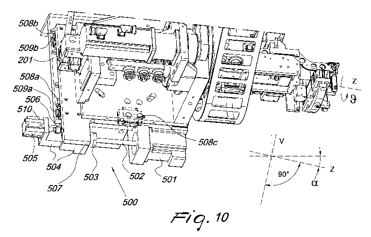
Figure 10 is a perspective view of the devices for establishing a
controlled and adjustable force of action of the sealing head and in
particular of the sealing nozzle against the face of the glass pane that is
offset with respect to the other glass pane.
Figure 11 completes Figure 10, using a different orientation to show
both the arrangement of the axes V. Z, 0 and the details of the sealing nozzle
of the suitable type and in the operating condition toward a perimetric joint,
the one on the lower side of the insulating glass, which one of the two panes
is offset with respect to the other one at least in one portion of the
insulating
glass.
Figure 12 is a schematic view of the principle of the approach of the
nozzle against the face of the offset part of the glass pane, a principle
which
reconciles the requirements of following the nonplanarity, which is shown
emphasized, of said glass pane and of applying toward said face a force
within an appropriate range of values, let us call it "soft", in order to
solve
the problems inherent in the background art, i.e., to avoid leaks of the
sealant toward said face and damage of the surface of said face.
CA 03113707 2021-03-22
WO 2020/074284 PCT/EP2019/076284
7
Figure 13 shows, separating them from the known devices of the
sealing head that are superfluous with respect to the inventive concept, all
the components (actuator, potentiometer, mechanical parts, etc.) the
interaction of which provides the "soft" operation shown in Figure 12.
Figures 14a-14d are views of the various configurations of the
insulating glass 1, limiting itself to the cases composed of two and three
glass panes, which can be sealed without problems by virtue of the claimed
device and method and shows a detail of the nozzle that highlights the lip
which has the function of providing a seal toward the face of the protruding
glass pane.
Figures 15a-15b show how the situations that are not solved in the
background art lead to aesthetic, functional and structural defects such as to
render the insulating glass product rated as defective and destined to be
discarded (contamination or scratching).
Figures 16a-16d show the shapes of the insulating glass units which
can be processed in the machine according to the invention.
Figure 17 is a view of an example of insertion of the automatic
sealing machine in the line for the production of the insulating glass (seen
from the side) and does not comprise: electrical/electronic panel, control
post and protection devices.
Figure 18 is a view of an example of insertion of the automatic
sealing machine in the line for the production of the insulating glass (seen
in
plan view) and includes: electrical/electronic panel, control post and
protection devices, be they of the type of mechanical shields or optical
barriers or laser barriers or electrosensitive mats, or zone scanners, etc.,
since particular attention is dedicated not only to the functional,
qualitative,
production aspects that are typical of the contents of the present invention
but also to the aspects that relate to accident prevention.
WAYS OF CARRYING OUT THE INVENTION
In order to describe one way of carrying out the invention, which
CA 03113707 2021-03-22
WO 2020/074284 PCT/EP2019/076284
8
comprises all the equivalent ones, reference is made to Figures 10, 11 for
the assemblies and Figures 12-15b for the details.
The products: insulating glass 1, glass pane 2, 2', 2", 2" etc., spacer
frame 3, 3', 3" etc., 4, 4', 4", etc., and additional components thereof are
identified by single-digit numbering, optionally provided with indices or
letters. In particular, in order to distinguish the various possible shapes of
the insulating glass, the reference numeral 1 designates the most frequent
(rectangular) situation, the reference numerals l' and 1' designates the
situations that can be processed in any case with the devices according to
the present invention (polygonal and mixed), the reference numeral 1"
designates the (completely curvilinear) shape which is rarely requested and
can be processed with the integration of devices, which are not innovative
and therefore not described, by the present invention. In particular, both for
an insulating glass production line that operates with a left-to-right
direction
and for an insulating glass production line that operates with a right-to-left
direction, the reference numeral la designates the vertical side that is
sealed
first, the reference numeral lb designates the upper horizontal side, the
reference numeral lc designates the vertical side that is opposite the
preceding vertical one, the reference numeral 1 d designates the lower
horizontal side, which is the one that rests on the conveyors and is entrained
by them. The various figures consider and provide a miscellany of both
cases, since they are not significant.
The components that are separate but interfaced with the automatic
sealing machine are designated by two-digit numbering.
The main components of the inventive device according to the present
application, identified in the assembly 500 and of the known correlated
devices identified in the assemblies 100, 200, 300, 400, are identified by
three-digit numbering, optionally provided with indices or letters, wherein
the ones that contain two zeroes relate to assemblies or units while the
others refer to the respective component details.
CA 03113707 2021-03-22
WO 2020/074284 PCT/EP2019/076284
9
The machines that belong to the production line of the insulating
glass 1 are identified by four-digit numberings, in the order according to
Figures 17 and 18, reserving the reference numeral 1000 for the automatic
sealing machine and, in the example of said figures: the reference numeral
2000 for the machine that removes any nanotechnology coating in the band
of the glass pane affected by the sealants; the reference numeral 3000 for the
machine that performs any grinding of the edge of the glass panes; the
reference numeral 4000 for the washer of the glass panes; the reference
numeral 5000 for the applicator of the spacer profile; the reference numeral
6000 for the coupling unit/press.
It should be stressed that the device and the method according to the
present invention deal with the implementation of important improvements
in the so-called SECOND SEALING or SECONDARY SEALING which
provides the structural and functional coupling of the set of components:
panes 2, 2', 2', 2" etc., spacer frame 3, 3', 3" etc., 4, 4' 4" etc., at the
perimeter, by means of polymeric sealants such as silicone, polysulfide,
polyurethane, hot-melt, etc., fluids which are typically non-Newtonian and
therefore have a complex rheology. The invention according to the present
application relates in particular to new and innovative components to allow
the operation of the machine that performs said sealing in the condition in
which the insulating glass 1 as assembled, in the machine 6000, before
sealing is not sufficiently planar and this by importing part of the solution
of
the prior art PCT/EP2018/072908 in the name of the same Applicant and
especially in the condition, not solved in the background art, in which the
sealing nozzle must provide a seal both against the perimetric edge of the
smaller glass pane and against the face of the larger glass pane in the
peripheral portions in which it is offset with respect to the smaller glass
pane (cases shown in Figures 1C, 1E, 1F).
Leaving aside the steps of the process before the sealing operation
that leads to the forming of the insulating glass panel to be sealed, since
CA 03113707 2021-03-22
WO 2020/074284 PCT/EP2019/076284
they are known and irrelevant with respect to the innovations introduced
with the present invention, the description referes the concepts of sealing to
introduce the innovative modifications that commingle in the background
art, in particular the nearest one according to PCT/EP2018/072908.
5 What
is shown partially in Figures 2-9 or can be deduced from them
as regards the sealing machine per se is also assumed to be known, and
therefore not requiring a detailed description but only a summary one (since
it is part of the background art), since the prior art described earlier and
the
numerous other prior art, as this field is very crowded with industrial
10
property titles, as well as the knowledge of the person skilled in the art, do
not require any clarification for the construction of these parts which relate
to the automatic sealing machine, which are essentially constituted by the
following assemblies: the reference numeral 100 for motion along the
synchronous horizontal axis H of the insulating glass panel through its
lower edge 1 d (Figures 5, 6); the reference numeral 100' for motion along
the synchronous horizontal axis H of the insulating glass panel 1 through its
front face or through its rear face (Figures 5, 6); the reference numeral 200
for motion of the sealing head along the synchronous vertical axis (or rather
pseudo-vertical, since it is slightly inclined with respect to the vertical by
an
angle a) V (Figures 5, 7); the reference numeral 300 for the extrusion head,
which rotates about the synchronous polar axis 0 and is adjustable along the
transverse axis Z (which is pseudo-horizontal, since it is slightly inclined
with respect to the horizontal by an angle a) and ends with the sealing
nozzle 301 (Figures 5-7); the reference numeral 400 for the dosing unit
assemblies (Figures 8a, 8b and 9).
A few details related to the background art are instead referenced as
regards the path of the sealant 5, 5', 5", etc., since it is correlated with
the
function of filling the perimetric joint in the various configurations. This
is
to point out that the final operation of the filling of the cavity one 1, l',
1",
l" with high-quality aesthetic results constitutes a process that is complex
CA 03113707 2021-03-22
WO 2020/074284 PCT/EP2019/076284
11
from the point of view of the automatic adjustment principles, toward which
the nonplanarity of the insulating glass and the offset between the glass
panes only increase the complexity of the requirements of the functions
required by the various devices. The sealants that are typically used are:
silicone, particular for structural glazing; polysulfide; polyurethane;
predominantly in the bi-component versions, i.e. the ones constituted by a
base product plus a catalyst product, to be dosed and mixed and, in the final
step, to be spread, filling the joint so as to constitute a geometry that is
perfectly aligned with the borders of the glass panes and, as mentioned
earlier, the rheology of sealants being complex.
The dosing assembly 400 is constituted by the dosing unit of the base
product B and by the dosing unit of the catalyst product C which, being
each in synchronous tie, can dispense the flow of the base product and the
flow of the catalyst product in the stoichiometric ratio required by the
manufacturer of the secondary sealant 5, 5', 5" etc. (typically 10:1 by
volume, but any ratio is adjustable by means of simple inputs in the control
panel 12). Obviously, in the case of mono-component sealant, the dosing
unit is only one, since the catalyst product is not present.
The dosing unit of the base product comprises the following essential
components: plunger or syringe 401B; cylinder or chamber 402B; seal
403B; recirculating ballscrew 404B; ballscrew nut 405B; mechanical
transmission 406B, for example of the sprocket/chain type; mechanical
reduction unit 407B; synchronous electric motor 408B. It is evident that
these components are coupled partly to an upper plate and partly to a lower
plate, said plates being connected by tension members, structural elements
which are shared and used by the dosing unit B of the base product and by
the dosing unit C of the catalyst product, as visible in Figures 8a and 8b.
The dosing unit of the base product comprises the following auxiliary
components, all of which also belong to the background art: valves, pressure
transducers, pressure gauges, protections against overpressures, etc.
CA 03113707 2021-03-22
WO 2020/074284 PCT/EP2019/076284
12
The dosing unit of the catalyst product comprises the following
components: plunger or syringe 401C; cylinder or chamber 402C; seal
403C; recirculating ballscrew 404C; ballscrew nut 405C; mechanical
transmission 406C, for example of the sprocket/chain type; mechanical
reduction unit 407C; synchronous and electric motor 408C, coupled as
mentioned earlier.
The dosing unit of the catalyst product also comprises the auxiliary
components as mentioned earlier.
In the case of mono-component sealant, the layout remains usable, but
a single dosing unit is involved.
The operating logic of all of these components is shown
schematically in Figure 9, which is intuitive to interpret, on the dispensing
side the flow rate of the dosing unit assembly being equal to c 1 x S1 + c2 x
S2; where c 1 and c2 are respectively the speeds of the syringes of the base
product and of the catalyst product, actuated by means of the actuations of
the motors 408B and 408C, and S1 and S2 are the corresponding sections
and on the destination side the same flow rate corresponding to the relative
speed between the extrusion nozzle 301 and the side of the insulating glass
1, l', 1", 1' multiplied by the section S of the perimetric joint, i.e. v x S.
Where S is the product of the width w of the spacer profile 3, 4 by the
distance d of its extrados from the margins of the glass panes 2, 2' as
measured continuously by the probe 304, the position of which is
feedbacked or retroacted by means of the potentiometer 305 toward the
programmable logic controller (PLC) 306.
Figure 9 shows other components, such as: the flow control valve
302; the mixer 303, for example of the static type, for the uniform mixing of
the components B (base) and C (catalyst), adapted to obtain the sealant 5
which catalyzes by chemical reaction between the two components, said
reaction typically occurring over 2 3 hours; the operator interface (HMI)
307, arranged in the control post 12 for dialog with the PLC.
CA 03113707 2021-03-22
WO 2020/074284 PCT/EP2019/076284
13
In detail, as regards the logic and power controls used to perform the
dispensing of the sealant product at the nozzle 301, they are managed by the
PLC 306, and the following are the main INPUTS and OUTPUTS:
INPUTS:
w = width of the spacer frame
d = distance of its extrados from the margin of the glass panes
v = relative speed of the peripheral region of the side of the insulating
glass
1, l', 1", l'"/extrusion nozzle 301
¨ signals from the pressure transducers
- feedbacks from the synchronous motors 408B and 408C
OUTPUTS:
¨ signals towards the actuation systems (not shown in the figure) of the
synchronous motors, such as to embody the equation vxS=c1 x 51 + c2 x
S2.
Other parameters reside in the PLC, such as for example the sections
51 and S2 of the syringes, since they are constant data.
This description refers to the more complete case of the bi-component
sealant. Obviously, it is applicable also to the case of the mono-component
sealant, simply by eliminating the parts that describe the catalyst fluid.
For the sake of simplicity, Figure 9 shows the case of the edge
portions of the glass panes 2, 2' in the alignment condition; for the case of
offset edge portions, to which the essence of the present invention is
dedicated, for example as shown in Figures 14a-14d and 15a-15b, the
equations remain unchanged and only the shape of the nozzle 301 changes.
The innovative and therefore inventive part of the present application
arises from the aim to eliminate the problems of the background art, which
are fundamentally exemplified in Figures 15a-15b, but what has been
devised must not be interpreted trivially as a solution that is obvious after
the fact because instead it reconciles an innovative combination of groups of
mechanisms in double feedback: along the axis Z, the first important
CA 03113707 2021-03-22
WO 2020/074284 PCT/EP2019/076284
14
assembly of the ones that actuate the following of the displacement of the
perimetric cavity of the insulating glass, which is not geometrically planar
due to the irregularities of the glass panes that constitute it, and, again
along
the axis Z, the second even more fundamental assembly of the ones that
actuate the control of the thrust of the portion of the nozzle 301 against the
protruding part of the face of the larger glass pane. This nozzle portion has
the function of retaining the sealant 5 so that its border in the face of the
protruding part of the glass pane is sharply defined and at the same level as
the edge of the smaller glass pane.
In order to follow the nonplanarity of the insulating glass by means of
the mechanisms of the first assembly, the principles of patent
PCT/EP2018/072908 are used to, improving them, using for example a
sensor 308 (Figure 3) which, axially integral with the carriage 507 (Figure
10) actuated along the transverse axis Z, detects the distance from the
closest glass pane and together with the data entries of the PLC that bear the
additional necessary information such as the thicknesses of the glass panes
2, 2', 2", 2" etc., the widths of the gaps 3, 3', 3" etc., 4, 4', 4" etc., and
together with the program of the PLC itself make the PLC process the
output for the actuator 501, which interacts between the body 201 of the
vertical carriage 200, which runs on rails 202a, 202b, and the carriage 507,
said actuator, by means of the ballscrew 502, the ballscrew nut 503, moves
said carriage 507, which runs along the transverse axis Z by means of the
ballscrew sliders 508a, 508b, 508c on the rails 509a, 409b of the body 201
of the vertical carriage, and with it the extrusion head 300 and therefore the
nozzle 301, which is thus arranged in the optimum position for sealing as a
function of the arrangement of the perimetric cavity or joint, which as
already revealed can include both the aligned edges and the offset edges
within the same insulating glass.
The second group of mechanisms intervenes between the ballscrew
nut 503 and the carriage 507, i.e., the group that performs, synergistically
CA 03113707 2021-03-22
WO 2020/074284 PCT/EP2019/076284
with the first group, control of the thrust of the portion of nozzle 301
against
the protruding part of the face of the larger glass pane. The first group in
fact performs a geometric positioning, the precision of which derives: from
the resolution of the signal of the sensor 308, from the control of the
5
actuation systems, from the accuracy of the machining, from the plays, from
the temperature, etc., and ends up having a resolution that is not better than
0.5 mm, and this entails, in case of separation of the nozzle from the face
of the glass pane, an outflow of the sealant toward said face with
corresponding contamination, and in case of interference between the nozzle
10 and the face of the glass pane, damage of the latter. The second group of
mechanisms is constituted by the following components: body 504;
pneumatic cylinder/compensator 505; stem 506; and, shared with the
mechanisms of the first group, the carriage 507. The way of operating of the
second group of mechanisms is as follows.
15 The
body 504, in which the ballscrew nut 503 is coupled, is not
rigidly integral with the carriage 507 but is interfaced with it by means of
an
elastic connection constituted by the "compensator" pneumatic cylinder 505,
the stem 506 of which is screwed and locked on a part of the carriage 507. It
is evident, therefore, that as a function of the pressures that can be
established in the pneumatic cylinder 505 the sealing head 300, and with it
the portion of the sealing nozzle 301 that is moving closer against the
protruding part of the face of the larger glass pane, can apply a "soft"
thrust
against the face of the protruding part of the larger glass pane. It is even
sufficient to work with the adjustment of the pneumatic pressure only in the
chamber of the pneumatic cylinder on the stem side (the chamber of the so-
called negative stroke). In fact, as shown in the diagram of Figure 10 and 11
and described regarding the background art, the mutually perpendicular axes
V and Z do not have respectively vertical and horizontal arrangements but
are slightly inclined with respect to them, typically by an angle a in the
range of 6+8 , since they are in alignment with the conveyors along which
CA 03113707 2021-03-22
WO 2020/074284 PCT/EP2019/076284
16
the insulating glass panels are translated along their production line, the
standards of the machines directive prescribing a minimum inclination of 5
degrees for the stability of the transfers (plus an increase which is a
function
of any seismic loads). It is evident, therefore, that this inclination of the
axis
Z with respect to the horizontal, already naturally, i.e., by virtue of the
action of the force of gravity, leads to a sliding (which originates on the
carriage 507, which slides by means of the sliders 508a-508c, along the rails
509a, 509b of the body 201 of the vertical carriage 200) for descent and
resting of the sealing head 300 and with it of the sealing nozzle 301 toward
the face of the larger glass pane. Therefore it is the adjustment of the
pressure in the negative chamber of the cylinder 505 that determines said
resting force, since the component along the axis Z of the weight of the
carriage 507 and of all the components installed therein, i.e., the ones that
belong to the head 300, is in excess with respect to the force that one wishes
to apply toward the face of the larger glass pane and therefore must be
discharged by virtue of the action of said pressure, which acts in the
pneumatic cylinder/compensator 505, until the ideal resting force is
obtained.
The component 510 shown in Figures 10 and 13 is constituted by a
potentiometer which detects the position of the piston inside the pneumatic
cylinder 505 and provides a feedback to the controller (PLC) 306 so that by
means of the actuation of the actuator 501 a rather centered position of the
pneumatic cylinder 505 with respect to the piston contained inside it is
restored, so that there is a work range for the "soft damping" of the nozzle
301 toward the face of the larger glass pane. Otherwise, one would run the
risk that if the piston reaches the negative stroke limit, the nozzle 301
detaches from the face of the larger glass pane and if it reaches the positive
stroke limit the nozzle 301 presses excessively against the face of the larger
glass pane.
In addition to the "soft damping" performed by the second group of
CA 03113707 2021-03-22
WO 2020/074284 PCT/EP2019/076284
17
mechanisms cited above, the coupling between the extrusion nozzle 301 and
the extrusion head 300 is provided in a slightly articulated manner in order
to follow any geometric irregularities of the edges of the glass panes and the
nonplanar geometry of the insulating glass, and this is done to prevent the
sealant 5 from escaping from the borders which must instead be hermetic
between the involved parts of the nozzle and of the glass panes. This joint is
of the spherical type in order to be able to perform oscillations both along
an
axis that is parallel to the face of the insulating glass and along an axis
that
is perpendicular to the face of the insulating glass.
In view of the wide range of the configurations of the cavities of the
perimetric edge of the insulating glass to be filled with the sealant,
obviously the nozzles 301 for the most frequent joint situations are provided
with the machine, whereas they are designed accordingly for particular
situations.
In all cases, the shapes of the nozzle 301 may be multiple, since they
have to interface with at least the following situations of the perimetric
joint
of the insulating glass, as shown by way of partial example in Figures 14a-
14d:
¨ edges aligned along the entire perimeter;
- edges not aligned along the entire perimeter with equal offset;
¨ edges not aligned along the entire perimeter with differentiated
offsets;
¨ edges aligned in some perimeter portions and not aligned in others;
¨ combinations of the situations cited above with rectangular or
nonrectangular shapes of the insulating glass;
¨ combinations of the situations cited above with a depth of the cavity
of the joint that is constant or different in the various perimeter portions
and
optionally is recessed in its external extrados with respect to the margin of
the smaller glass pane.
Since the most frequent situation is the one for which the nozzle 301
CA 03113707 2021-03-22
WO 2020/074284 PCT/EP2019/076284
18
must work within the same insulating glass both in conditions with edges
aligned in some portions of the perimeter and edges not aligned in some
other portions of the perimeter, it is necessary to adopt for the same nozzle
a
shape that is adapted both to be superimposed simultaneously and at least
partially on two edges and to be superimposed at least partially on one edge
and be arranged opposite one face, as shown in Figures 14a-14d. The
mechanisms for performing the alternation of the arrangements are the ones
as described of the first group, which therefore, in addition to having the
function of following the nonplanar arrangement of the perimetric cavity
have the function of moving transversely along the axis Z the nozzle 301
according to the type of the joint, portion by portion of the perimeter of the
insulating glass, or between one insulating glass and another insulating
glass if, as often occurs, insulating glass units with different shapes of the
perimetric joints follow one another.
The possibility is also mentioned and claimed to arrange the
mechanisms in double feedback, instead of as described in the preferred
embodiment of the invention between the body 201 of the vertical carriage
200 which moves along the vertical axis V and the carriage 507 which
moves along the transverse axis Z, rather proximate to the terminal part of
the extrusion head 300 directly upstream of the nozzle 301 in order to obtain
theoretically movements that are freer since they involve smaller masses and
run on carriages which are miniaturized and therefore have a reduced
friction. However, this solution is influenced by the noise introduced by the
sealant feed tube, which despite being flexible entails loads which are
additional and furthermore variable as a function of the type (as viscosity
changes) and of the flow rate of the sealant 5 toward the nozzle 301 and
therefore toward the protruding face of the larger glass pane.
INDUSTRIAL APPLICATION
Obviuosly, the industrial application is assuredly successful, since
machines for the automatic execution of the second sealing of the insulating
CA 03113707 2021-03-22
WO 2020/074284 PCT/EP2019/076284
19
glass 1, l', 1", 1' have undergone particular development over the last
decade, so much that the owner of the present application has already
marketed over four hundred units, but since these automatic sealing
machines have the severe limitations described in the background art section
they are not suitable to deal with the continuous architectural evolutions of
buildings, which require adaptations of all the elements that compose the
buildings, in particular of insulating glass units and more particularly of
structural insulating glass units.
Currently, the demand for types of insulating glass that are innovative
both in terms of shape and in terms of structural and functional performance
has undergone a surprising increase; it is sufficient to consider structural
glazing, which extends over heights of more than one story of the building,
or commercial insulating glazing, which reaches lengths of over 15 meters,
and the consequence that the large extensions of the surface entail the use of
equally important glass pane thicknesses and the use of glass pane
configurations which range from tempered to laminated and accordingly
their displacement from planar geometry, which is already per se present
due to the large dimensions, is therefore even more significant due to the
type. But most of all the configuration of the insulating glass units in which
the peripheral edges are not aligned has undergone unexpected
developments both in quantitative terms and in terms of types such as: the
wide range of the offset values between the panes, which today is extended
up to even 500 mm; the variety and combination of situations of aligned
edge/offset edge situations within the same insulating glass; the quantity of
panes within the same insulating glass, which is no longer limited to two as
in the past; the variability of the surface treatments of the protruding parts
of
the larger glass pane. Moreover, the supporting structures of glazing units
also have undergone evolutions in the shapes of the cross-sections and in
the materials, such as steel and aluminum originally and now also including
composites. And as already mentioned, the automatic sealing machine range
CA 03113707 2021-03-22
WO 2020/074284 PCT/EP2019/076284
according to the background art has turned out to be unsuitable for this
parallel development of the insulating glass final product, or able to solve
the problem only by means of predominantly manual palliatives.
The insertion of the present invention in the production line of the
5 insulating glass is shown in Figures 17 and 18 (side view and plan view
of a
solution in which the work direction is from right to left), as obvious
support to assured success in industrial application, in view of the by now
established but always evolving diffusion of these lines.
Moreover, the machine according to the present invention can be
10 implemented easily in existing lines, since as it performs the last work
of the
manufacturing process of the insulating glass it is a matter of replacing the
obsolete machine with said innovative machine without altering the
placement of all the upstream machines, intervening only on the terminal
part of the line, therefore reducing sometimes to a single day the
15 interruption of production in order to perform replacement or updates.
The disclosures in Italian Patent Application No. 102018000009336
from which this application claims priority are incorporated herein by
reference.
Where technical features mentioned in any claim are followed by
20 reference signs, those reference signs have been included for the sole
purpose of increasing the intelligibility of the claims and accordingly, such
reference signs do not have any limiting effect on the interpretation of each
element identified by way of example by such reference signs.