Note : Les descriptions sont présentées dans la langue officielle dans laquelle elles ont été soumises.
Attorney Ref.: 1147P142CA01
LABEL SHEET ASSEMBLY WITH PUNCTURE SURFACE FEATURES
FIELD OF INVENTION
The present disclosure generally relates to a label sheet assembly and method
of making a
label sheet assembly that is configured to be processed through a printer to
print indicia thereon.
More particularly, the disclosure relates to a label sheet assembly with
patterns of puncture
surface features that is configured to improve printer processing.
BACKGROUND
Labels and label sheets are well known, and various types have been proposed
to meet
the requirements of a wide variety of label applications. For example, labels
are extensively used
in retail businesses for communicating product information to customers.
Labels generally
include a facestock layer with an adhesive side and an exposed side. The
exposed side includes a
surface for receiving label indicia thereon and is opposite from the adhesive
side. A liner sheet is
operably attached to the adhesive side and is configured to allow a user to
peel the label portion
of the facestock from the liner sheet to be placed on a substrate. A plurality
of cut lines may
separate the facestock layer into a plurality of labels in various
arrangements.
Many label sheets are configured to be fed through a printer to print ink on
the surface of
the labels. For example, U.S. Patent No. 7,709,071 to Wong et al. discloses a
particular type of
label sheet assembly that is configured to be fed through a printer, and also
allows a user to
easily remove labels by hand. This patent is incorporated herein by reference
in its entirety.
These label sheet assemblies allow a user broad discretion as to the
orientation of the label and
the indicia to be printed thereon. However, problems arise when a user
processes label sheets
through a printer, such as an inkjet printer, desktop printer, or laser
printer. Many printers are
1
Date Recue/Date Received 2021-04-20
Attorney Ref.: 1147P142CA01
configured to receive a label sheet or other sheet and process it through at
least one, but usually
more than one, rotary mechanism during the printing process. These processes
may cause
portions of the label sheet assembly to become creased, manipulated or
otherwise disengaged.
This may cause ink to shift or labels to be moved relative the remaining
facestock layer or liner
sheet. This off-registration may be due, in part, to the level of friction
between a leading edge of
the label sheet and the receiving area of the printer device. Labels risk
damage and indicia may
not be accurately printed along the labels.
Therefore, there is a need for a label sheet assembly having a facestock and
liner material
that can be configured to reduce inconsistent processing through a printer.
There is also a need
for an improved method of feeding a label sheet through a printer to
accurately apply ink or
indicia thereon without unduly manipulating the orientation of the labels or
label sheet assembly.
SUMMARY
The present system leverages the advantages of a label sheet assembly with a
plurality of
puncture surface features arranged in a pattern. Provided are embodiments of a
label sheet
assembly that include a facestock layer having first and second sides, the
facestock layer
including at least one cut line that defines at least one label on the first
side wherein the facestock
layer is configured to receive indicia thereon. Additionally, a matrix
portion, or portion not
intended to receive indicia thereon, may be included in the facestock layer.
An adhesive layer is
provided along the second side and a liner sheet layer having top and bottom
surfaces, the top
surface attached to the adhesive layer along the facestock layer. At least one
puncture surface
feature is provided along a header portion or a footer portion of the label
sheet assembly,
wherein the at least one puncture surface feature may provide a zone of
increased tactile
2
Date Recue/Date Received 2021-04-20
Attorney Ref.: 1147P142CA01
sensitivity along the label sheet assembly. Further, the puncture surface
feature may also provide
a zone of increased friction thereon.
A first puncture surface feature may be applied along a header portion and may
include a
plurality of holes that extend through the facestock layer and the liner sheet
layer in a desired
pattern. A second puncture surface feature may be applied along a footer
portion and may
include a plurality of holes that extend through the facestock layer and the
liner sheet layer. The
at least one puncture surface feature may be configured in the form of a shape
such as a triangle,
octagon, square, arrow, star, rectangle, or any other shape. Also, the
puncture surface feature
may include a plurality of holes arranged in a pattern of letters or numbers.
Further, the pattern
of the puncture surface feature may be outlined with indicia along the header
portion and the
footer portion. Such indicia may include a border, pattern, color, image, or
font that is arranged
with the pattern of the plurality of puncture surface features. The puncture
surface features may
include a patterned solid color with contrasting indicia located along the
header or footer
portions.
In another aspect, this document discloses a label sheet assembly comprising:
a facestock
layer having first and second sides, the facestock layer including at least
one cut line that defines
at least one label and a matrix portion on the first side wherein the
facestock layer is configured
to receive indicia thereon; an adhesive layer along the second side; a liner
sheet layer having top
and bottom surfaces, the top surface attached to the adhesive layer along the
facestock layer; and
at least one puncture surface feature along the matrix portion of the
facestock layer, wherein the
at least one puncture surface feature includes a puncture hole that forms a
slightly concave shape
along one side and a slightly convex shape along the opposite side, and
wherein the at least one
puncture surface feature provides a zone of tactile sensitivity along the
label sheet assembly and
3
Date Recue/Date Received 2021-04-20
Attorney Ref.: 1147P142CA01
is configured to reduce off-registration of printed indicia along the at least
one label when
processed through a printer device.
In another aspect, this document discloses a label sheet assembly comprising:
a facestock
layer having first and second sides, the facestock layer including at least
one cut line that defines
at least one label and a matrix portion on the first side wherein the
facestock layer is configured
to receive indicia thereon; an adhesive layer along the second side; a liner
sheet layer having top
and bottom surfaces, the top surface attached to the adhesive layer along the
facestock layer; and
a plurality of puncture surface features along the matrix portion of the
facestock layer, wherein
the plurality of puncture surface features each include a puncture hole that
forms a slightly
.. concave shape along one side and a slightly convex shape along the opposite
side, and wherein
the plurality of puncture surface features provide a zone of tactile
sensitivity along the label sheet
assembly and is configured to reduce off-registration of printed indicia along
the at least one
label when processed through a printer device.
Specific reference is made to the appended claims, drawings, and description
below, all
of which disclose elements of the disclosure. While specific embodiments are
identified, it will
be understood that elements from one described aspect may be combined with
those from a
separately identified aspect, as combinations of the described features can be
exchanged and/or
replaced with the other disclosed features herein. In the same manner, a
person of ordinary skill
will have the requisite understanding of common processes, components, and
methods, and this
description is intended to encompass and disclose such common aspects even if
they are not
expressly identified herein.
4
Date Recue/Date Received 2021-04-20
Attorney Ref.: 1147P142CA01
BRIEF DESCRIPTION OF THE DRAWINGS
Operation of the disclosure may be better understood by reference to the
following
detailed description taken in connection with the following illustrations,
wherein:
Figure 1 is a cross sectional view of an embodiment of a label sheet assembly
of the
present disclosure;
Figure 2 is a perspective view of an embodiment of a label sheet assembly of
the present
disclosure with a plurality of puncture surface features;
Figure 3 is a perspective view of an embodiment of a label sheet assembly of
the present
disclosure with a plurality of puncture surface features;
Figure 4 is a plan view of an embodiment of the label sheet assembly of the
present
disclosure with a plurality of puncture surface features;
Figure 5 is a back view of an embodiment of the label sheet assembly of the
present
disclosure with a plurality of puncture surface features;
Figure 6 is a plan view of an embodiment of the label sheet assembly of the
present
disclosure with a plurality of puncture surface features;
Figure 7 is an enlarged perspective view of an embodiment of the label sheet
assembly of
Figure 3;
Figure 8 is an enlarged perspective view of another embodiment of the label
sheet
assembly in accordance with an embodiment of the present disclosure;
5
Date Recue/Date Received 2021-04-20
Attorney Ref.: 1147P142CA01
Figure 9A is an enlarged cross-sectional schematic view of a portion of the
label sheet
assembly illustrating a puncture surface feature and a method of forming the
puncture surface
feature according to the present disclosure;
Figure 9B is an enlarged cross-sectional schematic view of a portion of the
label sheet
assembly illustrating a puncture surface feature and a method of forming the
puncture surface
feature according to the present disclosure; and
Figure 10 is a front view of an image of an embodiment of the label sheet
assembly
illustrating a plurality of patterns and a plurality of puncture surface
features according to the
present disclosure.
DETAILED DESCRIPTION
Reference will now be made in detail to embodiments of the present disclosure,
examples
of which are illustrated in the accompanying drawings. It is to be understood
that other
embodiments may be utilized and structural and functional changes may be made
without
departing from the respective scope of the disclosure. Moreover, features of
the various
embodiments may be combined or altered without departing from the scope of the
disclosure. As
such, the following description is presented by way of illustration only and
should not limit in
any way the various alternatives and modifications that may be made to the
illustrated
embodiments and still be within the spirit and scope of the disclosure.
As used herein, the words "example" and "exemplary" mean an instance, or
illustration.
The words "example" or "exemplary" do not indicate a key or preferred aspect
or embodiment.
The word "or" is intended to be inclusive rather an exclusive, unless context
suggests otherwise.
As an example, the phrase "A employs B or C," includes any inclusive
permutation (e.g., A
6
Date Recue/Date Received 2021-04-20
Attorney Ref.: 1147P142CA01
employs B; A employs C; or A employs both B and C). As another matter, the
articles "a" and
"an" are generally intended to mean "one or more" unless context suggest
otherwise.
A label sheet assembly 10 is disclosed and may be of any appropriate
configuration and
is not limited to that shown and described herein. It should similarly be
understood that the sheet
assembly 10 may be adapted to any appropriate size, including, without
limitation, 8.5 inches by
11 inches, A4 size, legal size or any other size, including, without
limitation smaller sizes. The
sheet assembly 10 may be made of any appropriate materials and colors or
indicia and this
disclosure is not limited in this regard.
Figure 1 is a cross sectional side view of the sheet assembly 10 that may
include a
facestock layer 20 that may be coated with a pressure sensitive adhesive layer
30. The sheet
assembly 10 may also include a liner sheet 40 attached to the adhesive layer
30. The liner sheet
40 may include a release coating for supporting the adhesive layer 30. The
liner sheet 40 may be
made of any appropriate material, including, without limitation a calendared
paper or polymer
film. The facestock layer 20 may be of any appropriate material, including,
without limitation a
paper, plastic or polymer material such as a polyester material or other
transparent, translucent or
semi-translucent material. The facestock layer 20 may also be a laminate or a
label or
combination of both. The facestock layer may have a top surface 22 that is
configured to receive
indicia thereon.
As illustrated by Figures 2 and 3, the top surface 22 of facestock layer 20 in
embodiments
of the sheet assembly 10 are shown in a perspective view. The sheet assembly
10 may include at
least one cut line 50 that may extend through the facestock layer 20 to
separate the sheet
assembly into at least one label 60 and a matrix portion 70. In this
embodiment, the facestock
layer 20 includes thirty (30) labels 60 having a generally rectangular shape
with rounded corners,
7
Date Recue/Date Received 2021-04-20
Attorney Ref.: 1147P142CA01
wherein ten labels are aligned in each of three rows. However, this
application is not limited as
to the configuration, amount, or size of the labels 60. The present labels 60
are disclosed for the
sake of brevity, but the teachings herein apply to any number of labels, in
any number of
columns, and any size and shape of labels.
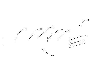
Turning to Figure 4, the label sheet assembly 10 may include a first edge 12
and opposite
second edge 14, along with a third edge 16 and opposite fourth edge 18. These
edges 12, 14, 16,
18 may intersect to form a generally rectangular sheet assembly, wherein the
label sheet
assembly 10 may be configured to be fed into a conventional printer device or
conventional
scanner device (such as, by way of a non-limiting example, an ink jet and/or
laser printer) from
any edge.
The label sheet assembly 10 may include various surface features in different
arrangements and be made from various materials, as disclosed in related U.S.
Patent
Application No. 15/813,693. In one embodiment, the surface feature is a
plurality of first
puncture surface features 80 that may be positioned along the matrix portion
70 of the facestock
layer 20. The puncture surface features 80 may be placed along and adjacent to
the first edge 12
between the third edge 16 and the fourth edge 18 as illustrated. This location
may be referred to
as the header portion 120. Further, there may be a plurality of puncture
surface features 90 that
may be positioned along the matrix portion 70 along an opposite side of the
label sheet assembly
10 as the first plurality of puncture surface features 80. These puncture
surface features 90 may
be placed along and adjacent to the second edge 14 and extend between the
third edge 16 and the
fourth edge 18. This location may be referred to as the footer portion 130. In
this embodiment,
the first and second edges 12, 14 may be shorter in length that the third and
fourth edges 16, 18.
Further, the first plurality of puncture surface features 80 may have a
different configuration than
8
Date Recue/Date Received 2021-04-20
Attorney Ref.: 1147P142CA01
the second plurality of puncture surface features 90, and the various
embodiments of the plurality
of puncture surface features 80, 90 may include a combination of surface
elements. The
combination may be optimized for traction, friction, tactile sensitivity and
flexibility to improve
processing through a printer or scanner device, ease of handling the sheets by
the user, and visual
aesthetics. Further, the plurality of puncture surface features 80, 90 may be
a zone of increased
flexibility imparted by coating or embossing to improve printer processing.
Printing processing
issues may be improved to reduce the skewing of printed indicia during
printing through a
printer device and reduce the occurrence of having multiple sheets fed through
the printer at
once, leading to jam.
As such, known label sheet assemblies may have experienced difficulty being
fed
through printers thereby causing indicia to be applied "off-register" or out
of alignment with the
intended position along the indicia receiving portions of the labels 60. This
off-registration may
be due, in part, to the level of friction between a leading edge of the label
sheet and the receiving
area of the printer device.
In one embodiment, the plurality of puncture surface features 80, 90 are added
to improve
the way in which label sheet assemblies 10 are fed through printers to receive
indicia on the
labels 60. The first and second plurality of puncture surface features 80, 90
may be provided to
improve the accuracy of indicia application while undergoing stresses caused
by processing the
label sheet assembly 10 though the printer. The first and second plurality of
puncture surface
features 80, 90 may have various orientations that improve frictional abutment
with the printer.
Additionally, the plurality of puncture surface features 80, 90 are flexible
enough to allow the
printer device to individually index the label sheet assemblies 10 as they are
positioned in a
stacked orientation relative to one another and being processed by the
printer.
9
Date Recue/Date Received 2021-04-20
Attorney Ref.: 1147P142CA01
The plurality of puncture surface features 80, 90 may include a plurality of
puncture
holes formed into a pattern 100A, 100B. Figures 9A and 9B illustrate that the
puncture holes
may be formed with a puncture tool 110 that includes at least one elongated
rigid member with a
piercing edge configured to pierce through and withdraw from the facestock
layer 20 and the
liner layer 40 in a desired pattern. The puncture tool 110 may include a
plurality of die pins
having piercing edges, or just a single die pin edge configured to extend
through and withdraw a
plurality of times to form the particular pattern 100. The puncture holes
include a perimeter that
includes a surface feature effect 140 relative to the remaining top surface 22
of the facestock
layer 20 or bottom surface 24 of the liner sheet layer 40. The surface feature
effect 140 of the
perimeter of the puncture holes 80, 90 may include a slightly concave shape
142 along one side,
along with a slightly convex shape 144 along the opposite side. The surface
feature effect 140
may be considered a textured edge along the header portion 120 or the feeder
portion 130 of the
label sheet assembly that improves printer feedability through a printer
device to print indicia on
the labels 60.
Figure 10 is an illustration of an embodiment of the label sheet assembly 10
that includes
a plurality of puncture surface features 80 along the header portion 120
within the matrix portion
70 of the facestock layer 20. The first row of labels 60 includes a matrix
portion 70 having a
plurality of puncture surface features 80 formed in a first pattern 100A (in
the shape of a triangle
or arrow) and a plurality of puncture surface features 80 formed in a second
pattern 100B (in the
shape of the font "AVERY"). Here, it was found desirable to form the first
pattern 100A with
puncture holes formed by the die pin 110 through the bottom side 24 (Figure
9A) to form the
slightly convex shape 144 along the top surface 22 for each of the plurality
of puncture surface
features 80 of the first pattern 100A. Also, the second pattern 100B is formed
by puncture holes
Date Recue/Date Received 2021-04-20
Attorney Ref.: 1147P142CA01
formed by the die pin 110 through the top side 22 (Figure 9B) to form the
slightly concave shape
142 along the top surface 22 for each of the plurality of puncture surface
features 80 formed in
the second pattern 100B.
Notably, in an embodiment, the first pattern 100A and the second pattern 100B
may
include a surrounding or outline pattern 150A, 150B having a color that is in
registry with the
plurality of puncture surface features 80 of the first pattern 100A or second
pattern 100B. The
outline pattern 150A, 150B may include a color or indicia that are generally
contrasted with the
remaining color or indicia along the remaining surface of the facestock layer
20 or liner layer 40
that is not a part of said pattern 100A, 100B. The resulting combination of
the puncture surface
features 80, along with the surrounding pattern 150A, 150B in registry, has
been found to
provide desirable visual and textural assistance to a user that allows the
user to easily visualize
the type of label sheet assembly 10 and an intended direction of printing
processing through a
printer device. The texture assists to increase friction with pick-up rollers
on consumer printers
or scanners that can sometimes have trouble properly processing label sheets
and feeding them
through the printer device while also receiving printed indicia on the labels
60. As can be further
seen from Figure 10, the first pattern 100A and second pattern 100B are
provided along a portion
of the header portion 120 in alignment with a second row of labels 60. Here,
the patterns 100A,
100B do not include the outline patterns 150.
The puncture surface features 80, 90 of the instant application have been
found to provide
a benefit over the surface features of existing label sheet assemblies, as
they do not require the
additional step of adding a layer of material, and provide the benefit of
reducing material and
manufacturing costs while also having the ability to provide slightly convex
and slightly concave
11
Date Recue/Date Received 2021-04-20
Attorney Ref.: 1147P142CA01
features along a pattern or shape along either side of the label sheet
assembly to assist with
processing multiple label sheets through a printer device reducing "off-
registration."
Although the embodiments of the present invention have been illustrated in the
accompanying drawings and described in the foregoing detailed description, it
is to be
understood that the present invention is not to be limited to just the
embodiments disclosed, but
that the invention described herein is capable of numerous rearrangements,
modifications and
substitutions without departing from the scope of the claims hereafter. The
features of each
embodiment described and shown herein may be combined with the features of the
other
embodiments described herein. The claims as follows are intended to include
all modifications
and alterations insofar as they come within the scope of the claims or the
equivalent thereof.
12
Date Recue/Date Received 2021-04-20