Note : Les descriptions sont présentées dans la langue officielle dans laquelle elles ont été soumises.
Description
Title of Invention: CLEANING KIT FOR AEROSOL
GENERATING DEVICE
Technical Field
L1-1 One or more embodiments relate to a cleaning kit for an aerosol
generating device,
and more particularly, to a cleaning kit for cleaning an aerosol generating
device by
moving while contacting an accommodation portion and a heater of the aerosol
generating device.
Background Art
[2] Recently, the demand for alternatives to traditional cigarettes has
increased. For
example, there is growing demand for an aerosol generating device that
generates
aerosols by heating an aerosol generating material, rather than by combusting
cigarettes. Accordingly, studies on a heating-type cigarette and a heating-
type aerosol-
generating device have been actively conducted.
[31 When an aerosol generating article (e.g., a cigarette) is heated to
generate an aerosol,
residual materials of the aerosol may adhere to an aerosol generating device
and may
cause damage or failure of the aerosol generating device, in addition, thermal
ef-
ficiency may be reduced, and an unpleasant odor may be generated while smoking
due
to incomplete combustion caused by the adhered residual materials.
[41 Thus, users need to individually clean an aerosol generating device.
However, it is
difficult for a user to cleanly clean residual materials adhered to the
aerosol generating
device through general cleaning tools.
Disclosure of invention
Technical Problem
[5.1 Residual materials adhered to the aerosol generating device may cause
damage or
failure of the aerosol generating device, and may cause discomfort to the user
by
changing the flavor of the generated aerosol.
[6] Accordingly, a cleaning kit for efficiently removing the residual
materials adhered to
the aerosol generating device needs to be provided to the user. For a complete
cleaning, the cleaning kit needs to be in close contact with components (for
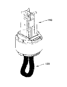
example, a
heater) of the aerosol generating device.
[7:1 The technical problems of the present disclosure are not limited to
the above-
described technical problems, and other technical problems may be derived from
the
embodiments to be described hereinafter.
Solution to Problem
[8:1 One or more embodiments include a cleaning kit for separating
residual materials
Date Recue/Date Received 2021-04-23
2
adhered to a heater unit and an accommodation portion of the aerosol
generating
device and removing the separated residual materials.
[91 According to an aspect of the present disclosure, a cleaning kit for
an aerosol
generating device includes a blade portion formed at one side of the cleaning
kit, and
configured to separate residual materials adhered to at least one of a heater
and an ac-
commodation portion of the aerosol generating device; and a brush portion
formed at
another side of the cleaning, kit, and configured to remove the separated
residual
materials from the aerosol generating device.
Advantageous Effects of Invention
[10] In a cleaning, kit for an aerosol generating device according to one
or more em-
bodiments, residual materials adhered to a heater unit and an accommodation
portion
of the aerosol generating device may be separated and removed from the aerosol
generating device A blade portion located at one side of the cleaning kit may
separate
the adhered residual materials while closely contacting the heater unit and
the accom-
modation portion. A brush portion located at the other side of the cleaning
kit may
remove the residual materials separated by the blade portion from the aerosol
generating device.
[11] By using the cleaning kit for an aerosol generating device according
to one or more
embodiments, a user may clean the aerosol generating device conveniently
without
using an additional cleaning tool or disassembling the aerosol generating
device.
[12] As the residual materials of the aerosol generating device are
removed, the risk of
damage or failure of the aerosol generating device may be reduced Also, as the
residual materials are removed, generation of unnecessary materials may be
prevented
when the aerosol generating device is heated, and an aerosol having a high
quality
flavor may be provided to the user.
Brief Description of Drawings
[13] FIG. 1 illustrates an example of an aerosol generating device.
[14] FIG. 2A is a perspective view of a cleaning kit for an aerosol
generating device
according to an embodiment.
[15] FIG. 2B is a perspective view of a cleaning kit for an aerosol
generating device
shown in FIG. 2A with cover portions removed.
[16] FIG. 3A is a perspective view of a cleaning kit for an aerosol
generating device
according to an embodiment.
[17] FIGS. 3B-3C are plan views of a blade portion shown in FIG. 3A.
[18] FIGS. 4 and 5 are views schematically illustrating the blade portion
of FIG. 3A
inserted into the aerosol generating device.
Best Mode for Carrying out the Invention
Date Recue/Date Received 2021-04-23
3
[ 19] According to an aspect of the present disclosure, a cleaning kit for
an aerosol
generating device includes a blade portion formed at one side of the cleaning
kit, and
configured to separate residual materials adhered to at least one of a heater
and an ac-
commodation portion of the aerosol generating device; and a brush portion
formed at
another side of the cleaning kit, and configured to remove the separated
residual
materials from the aerosol generating device.
[20] The blade portion and the brush portion may be arranged in series
along a lon-
gitudinal direction of the cleaning kit.
[21] The cleaning kit may further include cover portions configured to
cover the blade
portion and the brush portion.
[22] A through hole may be formed in the blade portion such that the
residual materials
separated from the heater and the accommodation portion are discharged through
the
through hole.
[23] The blade portion may include a first blade portion and a second blade
portion which
are configured to apply an elastic force that pulls the first blade portion
and the second
blade portion toward each other.
[24] A hollow may be formed between the first blade portion and the second
blade
portion, such that the heater is inserted into the hollow when the blade
portion is
inserted into the accommodation portion.
[25] A diameter of the hollow may be changed according to a diameter of the
heater when
the heater is inserted into the hollow.
[26] A bottom edge of the blade portion may be configured to contact a
bottom surface of
the accommodation portion when the blade portion is inserted into the
accommodation
portion
[27] The bottom edge of the blade portion may be curved, and curvature of
the bottom
edge may be reduced when the blade portion is inserted into the accommodation
portion_
[28] The blade portion may be formed as a leaf spring having elasticity.
[29] A side edge of the blade portion may be configured to contact an inner
wall of the ac-
commodation portion when the blade portion is inserted into the accommodation
portion.
[30] The side edge of the blade portion may extend in parallel with a
longitudinal central
axis of the blade portion.
Mode for the Invention
[31] With respect to the terms in the various embodiments, the general
terms which are
currently and widely used are selected in consideration of functions of
structural
elements in the various embodiments of the present disclosure. However,
meanings of
Date Recue/Date Received 2021-04-23
4
the terms can be changed according to intention, a judicial precedence, the
appearance
of a new technology, and the like. In addition, in certain cases, a term which
is not
commonly used can be selected. In such a case, the meaning of the term will be
described in detail at the corresponding portion in the description of the
present
disclosure. Therefore, the terms used in the various embodiments should be
defined
based on the meanings of the terms and the descriptions provided herein.
[32] In addition, unless explicitly described to the contrary, the word
"comprise" and
variations such as "comprises" or "comprising" will be understood to imply the
inclusion of stated elements but not the exclusion of any other elements. In
addition,
the terms "-er", "-or", and "module" described in the specification mean units
for
processing at least one function and/or operation and can be implemented by
hardware
components or software components and combinations thereof.
[33] In addition, terms used in the present specification are for
describing the em-
bodiments and are not intended to limit the embodiments. In the present
specification,
the singular form also includes the plurality form unless specifically stated
in the
phrase.
[34] Throughout the specification, the "longitudinal direction" of a
component may be a
direction in which the component extends along an axis in one direction of the
component, wherein the axis in one direction of the component extends longer
than an
axis in the other direction of the component crossing the axis in one
direction of the
component.
[35] As used herein, expressions such as "at least one of," when preceding
a list of
elements, modify the entire list of elements and do not modify the individual
elements
of the list. For example, the expression, "at least one of a, b, and c,"
should be un-
derstood as including only a, only b, only c, both a and b, both a and c, both
b and c, or
all of a, b, and c.
[36] It will be understood that when an element or layer is referred to as
being "over,"
"above," "on," "connected to" or "coupled to" another element or layer, it can
be
directly over, above, on, connected or coupled to the other element or layer
or in-
tervening elements or layers may be present. In contrast, when an element is
referred to
as being "directly over," "directly above," "directly on," "directly connected
to" or
"directly coupled to" another element or layer, there are no intervening
elements or
layers present. Like numerals refer to like elements throughout.
[37] Since various embodiments described in the specification are
classified arbitrarily
only for the purpose of explaining inventions, the embodiments should not be
construed to be exclusive to each other. For example, some features disclosed
in one
embodiments may be applied to or implemented in other embodiments. Also, it is
possible to change some features for applying or implement those features in
other em-
Date Recue/Date Received 2021-04-23
5
bodiments within scope and spirit of this disclosure.
[38] Hereinafter, the present disclosure will now be described more fully
with reference to
the accompanying drawings, in which exemplary embodiments of the present
disclosure are shown such that one of ordinary skill in the art may easily
work the
present disclosure. The disclosure may, however, be embodied in many different
forms
and should not be construed as being limited to the embodiments set forth
herein.
[39] FIG. 1 illustrates an example of an aerosol generating device 200.
[40] The aerosol generating device 200 is a subject to be cleaned with a
cleaning kit (see
100 of FIG. 2A) according to an embodiment. The aerosol generating device 200
may
include an accommodation portion 210 and a heater 220.
[41] The accommodation portion 210 of the aerosol generating device 200 may
ac-
comnrmdate a cigarette. The cigarette may be accommodated in the accommodation
portion 210 of the aerosol generating device 200, used, and then removed by a
user.
When the cigarette is heated or removed, residual materials of the cigarette
may adhere
to the accommodation portion 210 (e.g., side wall of the cavity for
accommodating a
cigarette), a bottom surface 230 of the accommodation portion 210, and the
heater 220
of the aerosol generating device 200. The residual materials generated from
the
cigarette may cause damage or failure of the aerosol generating device 200.
Also,
when the residual materials are heated, the flavor of an aerosol may be
deteriorated.
[42] The aerosol generating device 200 may include the heater 220. The
heater 220 of the
aerosol generating device 2(X) may be an electro-resistive heater 220. The
heater 220
may include an electrically conductive track, and the heater 220 may be heated
when
electrical current flows through the electrically conductive track. In the
aerosol
generating device 200 of FIG. 1, the heater 220 may be of a needle type.
However, the
shape of the heater 220 is not limited thereto, and the heater 220 may be of
an external
heating type and may have a shape surrounding the cigarette.
[43] Components relating to the cleaning kit 100 for an aerosol generating
device
according to an embodiment are shown in the aerosol generating device 200
shown in
FIG. 1. Thus, it will be understood by those skilled in the art relating to
embodiments
that other general components than the components shown in FIG. 1 may be
further
included in the aerosol generating device 200.
[44] The components of the aerosol generating device 200 shown in FIG. 1
may be
referred to below to describe the cleaning kit 100 for an aerosol generating
device
according to an embodiment in more detail.
[45] FIG. 2A is a perspective view of a cleaning kit 100 with a cover
portions 101 and
102 coupled to a body portion 103, according to an embodiment, and FIG. 2B is
a per-
spective view of a cleaning kit 100 without the cover portions 101 and 102.
[46] Referring to FIG. 2A, the external shape of the cleaning kit 100 for
an aerosol
Date Recue/Date Received 2021-04-23
6
generating device according to an embodiment is shown. The cleaning kit 100
for an
aerosol generating device according to an embodiment may include cover
portions 101
and 102 and a body portion 103. The cover portions 101 and 102 may include a
first
cover portion 101 and a second cover portion 102.
[47] The first cover portion 101 and the second cover portion 102 may
protect different
components of the cleaning kit 100 for an aerosol generating device. The first
cover
portion 101 and the second cover portion 102 may be arranged in series along a
lon-
gitudinal direction of the cleaning kit 100 and may be coupled to the cleaning
kit 100.
[48] The cover portions 101 and 102 may be coupled to the body portion 103
of the
cleaning kit 100 by interference fit or magnetism, for example. In a case
where the
cover portions 101 and 102 are coupled to the body portion 103 of the cleaning
kit 100
by interference fit, a hook portion (not shown) may be formed on the cover
portions
101 and 102, and an accommodation groove (not shown) for accommodating the
hook
portion may be formed on the body portion 103 of the cleaning kit 100. The
hook
portion formed on the cover portions 101 and 102 may be inserted into the
accom-
modation groove so that the cover portions 101 and 102 may be coupled to the
body
portion 103 of the cleaning kit 100.
[49] In a case where the cover portions 101 and 102 are coupled to the body
portion 103
of the cleaning kit 100 by magnetism, magnets may be arranged in each of the
cover
portions 101 and 102 and the body portion 103 of the cleaning kit 100. When
the cover
portions 101 and 102 are adjacent to the body portion 103 of the cleaning kit
1(X), the
magnets arranged on the cover portions 101 and 102 and the body portion 103
may
attract each other. Thus, the cover portions 101 and 102 and the body portion
103 may
be coupled to each other.
[50] At least part of the cover portions 101 and 102 may be separated from
the body
portion 103 when the cleaning kit 100 is used. That is, while part of the
cover portions
101 and 102 is connected to the body portion 103 or the cover portions 101 and
102
are fully separated from the body portion 103, the cleaning kit 100 may be
used by the
user.
[51] Internal components of the cleaning kit 100 for an aerosol generating
device
according to an embodiment will be described in detail with reference to FIG.
2B. FIG.
2B is a perspective view of the cleaning kit 100 shown in FIG. 2A with the
cover
portions 101 and 102 removed.
[52] The cleaning kit 100 for an aerosol generating device according to an
embodiment
may include a blade portion 110 located at one side of the body portion 103
and a
brush portion 120 connected to the opposite side of the body portion 103.
[53] The blade portion 110 may separate residual materials from the
accommodation
portion 210, a bottom surface 230 of the accommodation portion 210, and the
heater
Date Recue/Date Received 2021-04-23
7
220 of the aerosol generating device 200. The blade portion 110 may be
inserted into
the accommodation portion 210 of the aerosol generating device 200 and may
apply
force to components in the accommodation portion 210.
[54] When the blade portion 110 is inserted into the accommodation portion
210, the
blade portion 110 may be in close contact with each of the accommodation
portion
210, the bottom surface 230 of the accommodation portion 210, and the heater
220.
The blade portion 110 may be inserted into the accommodation portion 210 and
rotated
about a longitudinal axis of the accommodation portion 210. As the blade
portion 110
is rotated, the residual materials may be separated from the accommodation
portion
210, the bottom surface of the accommodation portion 210, and the heater 220.
[55] The brush portion 120 located at the other side of the body portion
103 may remove
the separated residual materials from the aerosol generating device 200. The
brush
portion 120 may include a plurality of fine hairs. The plurality of fine hairs
may collect
the residual materials adhered to the accommodation portion 210 of the aerosol
generating device 200, the bottom surface 230 of the accommodation portion
210, and
the heater 220, so that the residual materials may be removed.
[56] The user may use the blade portion 110 and the brush portion 120 to
clean the
aerosol generating device 200. For example, the user may insert the blade
portion 110
into the accommodation portion 210 of the aerosol generating device 200,
thereby
detaching the adhered residual materials from the accommodation portion 210,
the
bottom surface 230 of the accommodation portion 210, and the heater 220.
[57] Subsequently, the user may insert the brush portion 120, thereby
removing the
detached residual materials from the accommodation portion 210 of the aerosol
generating device 200, the bottom surface 230 of the accommodation portion
210, and
the heater 220. As the blade portion 110 and the brush portion 120 are
integrally
formed, the user may clean the aerosol generating device 200 more
conveniently.
[58] FIG. 3A is a perspective view of a blade portion 110 of a cleaning kit
100 for an
aerosol generating device according to an embodiment. A through hole 116 may
be
formed in the blade portion 110. Residual materials separated from a heater
220 and an
accommodation portion 210 may be collected from the aerosol generating device
through the through hole 116.
[59] For example, the blade portion 110 may be rotated about a longitudinal
axis of the
accommodation portion 210 while being inserted into the accommodation portion
210.
Thus, the residual materials may be separated from the accommodation portion
210, a
bottom surface 230 of the accommodation portion 210, and the heater 220. When
the
residual materials are separated, the through hole 116 formed in the blade
portion 110
may be a path through which the residual materials pass.
[60] The blade portion 110 may include a first blade portion 110a and a
second blade
Date Recue/Date Received 2021-04-23
8
portion 110b, which may apply an elastic force to each other. The blade
portion 110 may
be symmetrical. The first blade portion 110a and the second blade portion 110b
may be
apart from each other by a certain distance. A hollow 115 into which the
heater 220 is
inserted may be formed between the first blade portion 110a and the second
blade portion
110b. The first blade portion 110a and a second blade portion 110b may
respectively
include protrusion 110p. The protrusion 110p may protrude toward the hollow
115 and
form a part of the hollow 115. The first blade portion 110a and a second blade
portion
110b may respectively include groove 110g. The groove 110g may form a part of
the
hollow 115.
[61] The first blade portion 110a and the second blade portion 110b may
apply an elastic force
to each other. In other words, the elastic force may act in a direction in
which the first
blade portion 110a and the second blade portion 110b are pulled toward each
other. When
external force larger than the elastic force is applied to spread the first
blade portion 110a
and the second blade portion 110b, a separation distance between the first
blade portion
110a and the second blade portion 110b may increase.
[62] FIG. 313 is a plan view of the blade portion 110 shown in FIG. 3A
according to an aspect,
and FIG. 3C is a plan view of the blade portion 110 shown in FIG. 3A according
to
another aspect. Referring to FIGS. 38 and 3C, the appearance of one aspect and
another
aspect of the blade portion 110 may be shown in more detail.
[63] FIG. 3B is a plan view when no external force is applied to the first
blade portion 110a
and the second blade portion 11 Oh. For example, when the blade portion 110 is
not used, a
diameter of the hollow 115 between the first blade portion 110a and the second
blade
portion 110b may be dl.
[64] FIG. 3C is a plan view when an external force is applied to the first
blade portion 110a and
the second blade portion 110b. For example, when the blade portion 110 is
used, the
heater 220 may be inserted into the hollow 115 between the first blade portion
110a and
the second blade portion 110b. The diameter of the heater 220 may be greater
than the
diameter of the hollow 115. Therefore, as the heater unit 220 is inserted into
the hollow
115, the diameter of the hollow 115 may be changed to correspond to the
dimeter of the
heater 220.
[65] Comparing FIG. 3B with FIG. 3C, as the heater 220 is inserted into the
hollow 115, the
diameter of the hollow 115 between the first blade portion 110a and the second
blade
portion 110b may be changed from dl to d2. At this time, d2 may be greater
than dl.
[66] A spring may be arranged between the first blade portion 110a and the
second blade
portion 110b. When the distance between the first blade portion 110a and the
second blade
Date recue / Date received 2022-01-25
9
portion 110b increases, the spring may apply an elastic force in a direction
in which the
first blade portion 110a and the second blade portion 110b are pulled toward
each other.
[67] As the separation distance between the first blade portion 110a and
the second blade
portion 110b increases (for example, as the diameter of the hollow 115 is
changed from dl
to d2), the elastic force between the first blade portion 110a and the second
blade portion
110b may increase. Thus, an inner surface of the first blade portion 110a and
an inner
surface of the second blade portion I lob, which form the hollow 115, may be
in close
contact with the inserted heater 220,
[68] FIGS. 4 and 5 are views schematically illustrating eonesponding
components when the
blade portion 110 shown in FIG. 3A is inserted into the aerosol generating
device 200.
[69] FIGS. 4 and 5 show how the aerosol generating device 200 contact the
blade portion 110
when the blade portion 110 is inserted into the aerosol generating device 200.
[70] When the blade portion 110 is inserted into the aerosol generating
device 200, the blade
portion 110 may come in contact with corresponding portions of the aerosol
generating
device 200.
[71] When the blade portion 110 is inserted into the accommodation portion
210 of the aerosol
generating device 200, the heater 220 may be inserted into the hollow 115 of
the blade
portion 110.
[72] As described above with reference to FIGS. 3B and 3C, when the heater
220 is inserted
into the hollow 115 of the blade portion 110, the diameter of the hollow 115
may be
changed to correspond to the size of the heater 220. By elastic force between
the first
blade portion 110a and the second blade portion I 10b, the blade portion 110
and the
heater 220 may contact each other closely.
[73] Also, when the blade portion 110 is inserted into the accommodation
portion 210 of the
aerosol generating device 200, an end 112 of the blade portion 110 may contact
the
bottom surface 230 of the accommodation portion 210 of the aerosol generating
device
200. Contact between an end 112 of the blade portion 110 and the bottom
portion 230 of
the accommodation portion 210 may be secured by the user's external force.
[74] In an embodiment where the blade portion 110 may include the first
blade portion 110a
and the second blade portion 110b as described in FIGS. 3B and 3C, the bottom
edges of
the first blade portion 110a and the second blade portion 110b may the bottom
surface 230
of the accommodation portion 210. The separation distance between the bottom
edges 112
may be changed according to changes in the separation distance between the
first blade
portion 110a and the second blade portion 110b.
[75] For example, as the blade portion 110 is inserted into the
accommodation portion 210 and
the separation distance between the first blade portion 110a and the second
blade portion
Date recue / Date received 2022-01-25
10
110b increases from di to d2, a distance between the bottom edges 112 may
increase by a
difference between di and d2. Also, as the blade portion 110 is withdrawn from
the
accommodation portion 210 and the separation distance between the first blade
portion
110a and the second blade portion 110b decreases from d2 to dl, the distance
between the
bottom edges 112 may decrease by a difference between di and d2.
[76] Also, when the blade portion 110 is inserted into the accommodation
portion 210 of the
aerosol generating device 200, side edges 113 of the blade portion 110 may be
in contact
with an inner wall of the accommodation portion 210. The inner wall of the
accommodation portion 210 may form a cavity for accommodating a cigarette and
may be
arranged to surround the heater 220. The side edges 113 of the blade portion
110 may be
an edge farthest from the longitudinal central axis of the blade portion 110
in a radial
direction.
[77] The blade portion 110 may include four side edges 113, for example. In
an embodiment
where the blade portion II 0 includes the first blade portion 110a and the
second blade
portion 110b, two side edges 113 may be foimed on each of the first blade
portion 110a
and the second blade portion 110b. The side edges 113 may be formed to extend
in
parallel with the longitudinal central axis of the blade portion 110.
[78] The blade portion 110 may be a leaf spring and may have certain
elasticity. As shown in
FIG. 4, the bottom edge 112 of the blade portion 110 may be curved convexly
toward the
longitudinal central axis of the blade portion 110. When the blade portion 110
is inserted,
the blade portion 110 may he deformed by contact with the accommodation
portion 210
such that the curvature of the blade portion 110 is reduced. For example,
pressure may be
applied to the blade portion 110 in a direction perpendicular to the
longitudinal central
axis of the blade portion 110 such that the radius of curvature of the blade
portion 110
may be reduced.
[79] FIG. 5 illustrates components of the aerosol generating device 200
which contact the blade
portion 110, according to an embodiment.
[80] When the blade portion 110 is inserted into the accommodation portion
210, the hollow
115 of the blade portion 110 may be in contact with the heater 220, and the
bottom edges
112 of the blade portion 110 may be in contact with the bottom surface 230 of
the
accommodation portion 210, and the side edges 113 of the blade portion 110 may
be in
contact with the inner wall of the accommodation portion 210.
[81] That is, the blade portion 110 may come into close contact with the
heater 220, the bottom
surface 230 of the accommodation portion 210, and the inner wall of the
accommodation
portion 210, and may be rotated while maintaining the contact. As the blade
portion 110 is
inserted into the accommodation portion 210, the longitudinal central axis of
the hollow
Date recue / Date received 2022-01-25
11
115 of the blade portion 110 and the longitudinal central axis of the heater
220 may
coincide with each other, and the blade portion 110 may be rotated about the
longitudinal
central axis of the heater 220.
[82] When the blade portion 110 is rotated, a frictional force may act
between the blade portion
110 and the components positioned in the accommodation portion 210 (i.e., the
bottom
surface 230 of the accommodation portion 210, the inner wall of the
accommodation
portion 210, and the heater 220). Thus, the residual materials may be
separated from the
bottom surface 230 of the accommodation portion 210, the inner wall of the
accommodation portion 210, and the heater 220.
[83] The cleaning kit 100 for an aerosol generating device according to the
above-described
embodiments may separate the residual materials adhered to the heater 220 and
the
accommodation portion 210 of the aerosol generating device 200, and may remove
the
separated residual materials from the aerosol generating device 200. The blade
portion 110
formed at one side of the cleaning kit 100 may be in contact with the heater
220 and the
accommodation portion 210 to separate the adhered residual materials, and the
brush
portion 120 foimed at the other side of the cleaning kit 100 may remove the
residual
materials separated by the blade portion 110 from the aerosol generating
device 200.
[84] Through the cleaning kit 100 for an aerosol generating device
according to embodiments,
the user may clean the aerosol generating device 200 conveniently without
using an
additional cleaning tool or disassembling the aerosol generating device 200.
[8.5] As the residual materials of the aerosol generating device 200 are
removed, the risk of
damage or failure of the aerosol generating device 200 may be reduced, and
unnecessary
materials may be prevented from generating when the aerosol generating device
is heated.
Thus, an aerosol having a high quality flavor may he provided to the user, and
the user's
satisfaction may be improved.
[86] Those of ordinary skill in the technical field related to the present
embodiments will
understand that the present disclosure may be implemented in a modified form
without
departing from the essential characteristics of the above-described
description. The
disclosed methods should be considered in a descriptive sense only and not for
purposes
of limitation. The scope of the present disclosure is shown in the claims
rather than the
foregoing description, and all differences within the scope equivalent thereto
should be
interpreted as being included in the present disclosure.
Industrial Applicability
[87] One or embodiments relate to a cleaning kit for an aerosol generating
device that may
clean the aerosol generating device while contacting an accommodation portion
and a
heater of the aerosol generating device.
Date recue / Date received 2022-01-25