Note : Les descriptions sont présentées dans la langue officielle dans laquelle elles ont été soumises.
SELF-RETRACTABLE STEP
BACKGROUND OF THE INVENTION
A. Technical field
[0001] The present application generally relates to a floor mounted
retractable step. More
specifically, the present application relates to a self-retractable step for
assisting a user in
elevating him or herself above a floor, particularly to access a sink.
B. Description of related art
[0002] Handwashing greatly contributes to public health. However, sinks are
inaccessible to
low height persons in virtually all public washrooms as very few of them are
equipped with
elevating devices or low sinks. Low height persons are little people and small
children. If
parents want their children to wash their hands in public restrooms, they have
to lift and
squeeze them between themselves and the countertop in order to raise the child
to the right
height. This uncomfortable arrangement is strenuous both to the child who is
being held in a
strained position and to the parent who has to lift the child. More often than
not, little people
are not accompanied by a taller person who can lift them, so there is no way
for them to use
sinks in public restrooms. Few prior-art references addressing the foregoing
issues are
discussed as follows.
[0003] US9611691 of John Scott Hunter et al. discloses an in-cabinet step
stool. The in-
cabinet step stool for use with a cabinet defines an interior area, the in-
cabinet step stool
includes a framework having a pair of upstanding side walls, each side wall
having a rear
section and a front section extending forwardly and downwardly from the rear
section. An
upper step spans between upper edges of respective rear sections. A lower step
spans between
upper edges of respective lower sections. Each includes a rear foot having a
rounded
configuration such that the framework is pivotally movable thereon between a
deployed
configuration in which the rear foot rests upon the bottom wall of the cabinet
and the front
section extends forwardly through the opening of the cabinet and a stored
configuration in
which the rear foot rests upon the bottom wall of the cabinet and the front
section is inside the
1
Date Recue/Date Received 2021-09-13
CA 03116904 2020-12-15
WO 2020/082188 PCT/CA2019/051516
cabinet interior area. The in-cabinet step stool is necessarily designed to be
installed in a
cabinet under a sink, where a bottom wall of the cabinet is higher than the
floor in front of the
sink. As shown in Figure 5 of US9611691, this configuration adds to the
required height of
the step stool because the front feet must reach the floor while the rear feet
are disposed on the
bottom cabinet wall. This makes the step stool bulky. Further, the step stool
is pulled out of
the cabinet and returned to the cabinet using a hand-operated mechanism. This
forces a user
to touch a surface in a bathroom which may not be hygienic.
[0005] US2881040 of Hartridge Virginia Masden discloses a disappearing and
slidable step-
chair for kitchen cabinets and the like. A recessible combination step ladder
and chair has been
provided, which is adapted to he slid along the front of a kitchen counter on
a guide track for
access to any one of a plurality of upper cabinets and which is also adapted
to be pivoted about
said track for being recessed within one of the counter cabinets for storage.
Even though, the
prior art references provide functionality to assist the user in elevating him
or herself above the
floor, they lack to provide optimal functionality to the user and also the
used needs to move the
device to storage position manually. Further, they are installed in the
cabinet.
[0006] Henceforth, there is a need to provide a self-retractable step
comprising an economical
design for assisting a user in elevating him or herself above a floor.
SUMMARY OF THE INVENTION
[0007] The present application discloses a self-retractable step for assisting
a person in
elevating him or herself above a floor, particularly to access a sink.
[0008] According to the present application, the self-retractable step
comprises a self-
retractable foot member and a cylindrical assembly coupled with the self-
retractable foot
member. The foot member is configured to move from one position to another
position. In one
embodiment, the foot member is configured to move between a vertical position
or rest position
and a horizontal position or deployed position The cylindrical assembly
comprises a rotary
member, one or more spring members and a protuberance member. The rotary
member is
configured to move the foot member to a predetermined position. In one
embodiment, the
rotary member is configured to move the foot member to the horizontal
position.
[0009] Further, the spring members coupled to the rotary member is configured
to self- retract
the foot member from the predetermined position. In one embodiment, the spring
members is
configured to self-retract the foot member from the horizontal position to the
vertical position.
2
CA 03116904 2020-12-15
WO 2020/082188 PCT/CA2019/051516
The protuberance member disposed at the cylindrical assembly is configured to
act as a stopper
to hold the foot member in a predetermined position on retraction by the
spring members. In
one embodiment, the protuberance member is configured to act as a stopper to
hold the foot
member in the vertical position on retraction by the spring members. The self-
retractable step
further comprises a load bearing member at a base of the foot member. In one
embodiment, the
load bearing member is configured to hold the foot member above ground level
on horizontal
position. In one embodiment, the foot member is a stair member comprising at
least two steps.
[0010] In some embodiments, the present disclosure relates to a self-
retractable step which
may include a foot member and a cylindrical assembly. The foot member may
include at least
two steps and a load bearing member disposed on a base of the foot member. The
cylindrical
assembly may be coupled to the foot member and mountable on a floor, and may
include a
rotary member configured to move the foot member between a horizontal position
and a
vertical position.
[0011] The self-retractable assembly of the present disclosure may include any
of the
following features independently or in any combination. The cylindrical
assembly may
include one or more spring members configured to retract the foot member and
the one or more
spring members may be attached to the rotary member. One or more wheels may be
provided
between the spring members and the cylindrical assembly and each of the wheels
may have
one or more holes, wherein the wheels are configured to vary the strength of
the spring
members. The spring members may be configured to retract the foot member from
the
horizontal position to the vertical position. The cylindrical assembly may
include a
protuberance member configured to act as a stopper to hold the foot member in
a
predetermined position. The self-retractable step may be configured such that
deployment of
the foot member is performed by placing the foot and pressing downward on at
least one step
The at least two steps of the foot member may include an upper step and a
lower step, and
wherein a depth of the lower step is less than a depth of the upper step. The
load bearing
member may be recessed from a front edge of the foot member.
[0012] In some embodiments, the present disclosure relates to a self-
retractable step which
may include a foot member and a rotation assembly. The foot member may include
at least a
first step and a second step, and a load bearing member disposed on a base of
the foot member.
The rotation assembly may be coupled to the foot member and configured to be
mounted on a
3
CA 03116904 2020-12-15
WO 2020/082188 PCT/CA2019/051516
fixed horizontal surface. The rotation assembly may include a rotary member
configured to
allow the foot member to rotate from a use position to a rest position
relative to the fixed
surface.
[0013] The self-retractable assembly of the present disclosure may include any
of the
following features independently or in any combination. The rotation assembly
may include
a retraction mechanism configured to retract the foot member from the use
position to the rest
position. The retraction mechanism may include one or more biasing members and
/ or a
motor. The rotation assembly may include one or more dampeners attached to the
biasing
members. The cylindrical assembly may be configured to support a load applied
via the foot
member. The first step may have a height of ten inches and a depth of six
inches and the
second step may have a height of five inches and a depth of four inches. The
rotation assembly
may include a stopper to hold the foot member in the rest position. The
rotation assembly may
have a curved upper surface and the foot member may have a curved surface
which mates with
the curved upper surface of the rotation assembly. A depth of the first step
may be between
50% and 80% of a depth of the second step. The load bearing member may be
disposed at a
distance from a front edge of the foot member and at a distance from two side
edges of the foot
member. The foot member may include an angled front edge, angled such that a
user can read
instructions displayed on the angled front edge when the foot member is in a
rest position.
[0014] In some embodiments, the present disclosure relates to a system
comprising a floor, a
sink, and a self-retractable step moon the floor, such that a foot member of
the self-retractable
step is entirely disposed at least three inches behind a front edge of the
sink in a rest position.
The self-retractable step may have any of the features described above.
[0015] Other objects, features and advantages of the present invention will
become apparent
from the following detailed description It should be understood, however, that
the detailed
description and the specific examples, while indicating specific embodiments
of the invention,
are given by way of illustration only, since various changes and modifications
within the spirit
and scope of the invention will become apparent to those skilled in the art
from this detailed
description.
BRIEF DESCRIPTION OF DRAWINGS
[0016] The foregoing summary, as well as the following detailed description of
the invention,
is better understood when read in conjunction with the appended drawings. For
the purpose
4
CA 03116904 2020-12-15
WO 2020/082188 PCT/CA2019/051516
of illustrating the invention, exemplary constructions of the invention are
shown in the
drawings. However, the invention is not limited to the specific methods and
structures
disclosed herein. The description of a method step or a structure referenced
by a numeral in a
drawing is applicable to the description of that method step or structure
shown by that same
numeral in any subsequent drawing herein.
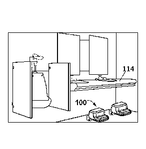
[0017] FIG. 1A exemplarily illustrates a self-retractable step installed
beneath a sink,
according to one embodiment of the present invention.
[0018] FIG. 1B exemplarily illustrates operation of at two self-retractable
steps installed
beneath the sink, according to one embodiment of the present invention.
[0019] FIG. 2 exemplarily illustrates a perspective view of the self-
retractable step,
according to one embodiment of the present invention.
[0020] FIG. 3 exemplarily illustrates a rear view of the self-retractable
step, according to
one embodiment of the present invention.
[0021] FIG. 4 exemplarily illustrates a perspective view of a cylindrical
assembly,
according to one embodiment of the present invention.
[0022] FIGS. 5A-5B exemplarily illustrate a side view and a front view of the
self-
retractable step, according to one embodiment of the present invention.
[0023] FIG. 6A exemplarily illustrates a partially assembled view of a self-
retractable step
according to the present disclosure.
[0024] FIG. 6B exemplarily illustrates a close-up partially assembled view of
a self-
retractable step according to the present disclosure.
[0025] FIG. 6C exemplarily illustrates a close-up partially assembled view of
the self-
retractable step showing multiple holes for receiving a biasing member
according to the
present disc] osure
[0026] FIG. 7A exemplarily illustrates an end piece in accordance with the
present
disclosure.
[0027] FIG. 7B exemplarily illustrates an end piece and a plate in accordance
with the
present disclosure.
[0028] FIG. 7C exemplarily illustrates a cross-section view of an end piece in
accordance
with the present disclosure.
5
CA 03116904 2020-12-15
WO 2020/082188 PCT/CA2019/051516
DETAILED DESCRIPTION OF EMBODIMENTS
[0029] A description of embodiments of the present invention will now be given
with
reference to the Figures. It is expected that the present invention may be
embodied in other
specific forms without departing from its spirit or essential characteristics.
The described
embodiments are to be considered in all respects only as illustrative and not
restrictive.
[0030] Referring to FIG. 1A and FIG. 1B, the present invention discloses a
self- retractable
step 100 for assisting a user in elevating him or herself above a floor.
Referring to FIG. 2,
according to the present invention, the self-retractable step 100 comprises a
self- retractable
foot member 102 and a cylindrical assembly 104 coupled to the foot member 102.
In one
embodiment, the self-retractable foot member 102 is configured to move from
one position to
another position. In one embodiment, the foot member 102 is configured to move
to a
predefined position via a rotary member of the cylindrical assembly 104.
Further, the foot
member 102 is configured to retract from the predefined position automatically
via one or more
spring members 112 of the cylindrical assembly 104.
[0031] In another embodiment, the foot member 102 is configured to move
between a vertical
position and a horizontal position. In one embodiment, the foot member 102 is
configured to
move to the horizontal position via the rotary member of the cylindrical
assembly 104. Further,
the foot member 102 is configured to retract to the vertical position or rest
position
automatically via the spring members 112 of the cylindrical assembly 104.
[0032] Referring to FIG. 2, the foot member 102 is a stair member comprising
at least two
steps 106. In one embodiment, the foot member 102 is displaced from the
vertical position to
the horizontal position by placing a foot upon at least one step 106 of the
stair member.
Referring to FIG. 3, the cylindrical assembly 104 coupled to the self-
retractable foot member
102 is illustrated.
[0033] Referring to FIG. 4, the cylindrical assembly 104 of the foot member
102 is illustrated.
The cylindrical assembly 104 comprises a protuberance member 110, the rotary
member and
the spring members 112. In one embodiment, the rotary member is configured to
move the foot
member 102 to the horizontal position. In one embodiment, the spring members
112 coupled
to the rotary member is configured to self-retract the foot member 102 from
the horizontal
position to the vertical position In one embodiment, the protuberance member
110 is disposed
at the cylindrical assembly 104 is configured to acta stopper to hold the step
in the vertical
6
CA 03116904 2020-12-15
WO 2020/082188 PCT/CA2019/051516
position on retraction by the spring members 112.
[0034] Referring to FIG. 5A, a base of the foot member 102 further comprises
at least one
load bearing member 108, which is adapted to hold the foot member 102 above
ground level
during horizontal position. In one embodiment, the dimensions of the self-
retractable step 100
may varies. In one embodiment, wheels with one or more holes are provided
between the
cylindrical assembly 104 and the spring members 112 to vary the strength of
the spring
member 112. In one embodiment, the cylindrical assembly 104 is made of
material including,
but not limited to, molded plastic. The foot member 102 can be manufactured
from various
materials. For example, the main body can be made from plastic by roto-molding
with anti-
slip members 106a and 106b being glued or bonded thereto. Injection molding of
plastic parts
can also be suitable to be assembled to form the member 102.
[0035] During operation of the present invention, deployment of the foot
member 102 is done
by placing the foot and pressing downward on at least one step 106. The rotary
member moves
the foot member 102 from the rest position to the horizontal position due to
the force applied
by the foot of the user. Further, on removing the foot from the steps 106, the
spring members
112 of the cylindrical assembly 104 is adapted to automatically retract the
foot member 102 to
the rest position.
[0036] Advantageously, the present invention assists the user in elevating him
or herself above
the floor to access the sink. Further, the stair member comprising at least
two steps 106
facilitates easy access to the user, such as children or little people, of
self-retractable step 100.
According to the present invention, the self-retractable functionality allows
automatic
transition to storage position or vertical position of the self-retractable
step 100.
[0037] Preferred embodiments of this invention are described herein, including
the best mode
known to the inventors for carrying out the invention It should be understood
that the illustrated
embodiments are exemplary only, and should not be taken as limiting the scope
of the
invention.
[0038] The foregoing description comprise illustrative embodiments of the
present invention.
Having thus described exemplary embodiments of the present invention, it
should be noted by
those skilled in the art that the within disclosures are exemplary only, and
that various other
alternatives, adaptations, and modifications may be made within the scope of
the present
invention. Merely listing or numbering the steps of a method in a certain
order does not
7
constitute any limitation on the order of the steps of that method. Many
modifications and other
embodiments of the invention will come to mind to one skilled in the art to
which this invention
pertains having the benefit of the teachings presented in the foregoing
descriptions. Although
specific terms may be employed herein, they are used only in generic and
descriptive sense and
not for purposes of limitation. Accordingly, the present invention is not
limited to the specific
embodiments illustrated herein.
100391 Additional features and advantages of the embodiments disclosed above
are described
below with reference to Figures 1-5. In general, the present disclosure
relates to a step which
may be used by a child to reach a sink. The step may include a mechanism by
which it
automatically retracts to a rest position when it is not in use. The step 100
may comprise a foot
member 102 which is configured to be stood on by a user and a rotation
assembly 104 which is
configured to allow the foot member to rotate between a rest position and a
use position. In some
embodiments, the foot member 102 may include a first step 106a and a second
step 106b. In
some embodiments, the rotation assembly 104 may be a cylindrical assembly as
described above.
100401 As discussed above, the foot member 102 may include two or more steps
106a, 106b and
a load bearing member 108. The stepping surfaces of steps 106a, 106b may be
covered by a slip-
proof material or may be textured during a manufacturing process so that they
have slip proof
surfaces. The foot member 102 may have a sloped rear surface 118, which may
allow the second
step 106b to be in a forward position relative to a point at which the foot
member 102 connects
to the rotation assembly 104.
[0041] The load bearing member 108 is shown clearly in Figures 5A-5B. The load
bearing
member 108 may extend from a base / a bottom surface of the foot member 102.
The load bearing
member 108 may be disposed in the center of the foot member 102 relative to
the width of the
foot member 102, as shown in Figure 5A. Accordingly, the load bearing member
108 may be
disposed at a distance of one inch (2.54 cm) to five inches (12.7 cm) from
each lateral edge of
the foot member 102. The load bearing member 108 may be offset from a front
edge of the foot
member 102, as shown in Figure 5B. Accordingly, the load bearing member 108
may be disposed
at a distance of one inch (2.54 cm) to five inches (12.7 cm) from the front
edge of the foot
member 102. In some embodiments, the load bearing member 108 may be disposed
several
inches or more from all edges of the foot member 102. This arrangement may
prevent users' feet
from becoming trapped/ pinched under the load bearing member 108 when the foot
member 102
is moved into a use position. In some embodiments, the load bearing member 108
may be
8
Date Recue/Date Received 2021-09-13
positioned on the base of the foot member 102 based on manufacturing
considerations. For
example, the load bearing member 108 may be disposed under both the first step
106a and the
second step 106b. The position of the load bearing member 108 may support
weight applied via
either stepping surface of steps 106a, 106b and may allow the foot member 102
to be
manufactured as a partially or substantially hollow unit.
100421 The rotation assembly 104 may be attached to a fixed surface such as a
floor and may
allow the foot member 102 to rotate relative to the fixed surface. The
rotation assembly 104 may
allow the foot member 102 to move between a use position and a rest position.
In some
embodiments, the use position may be substantially horizontal, such that the
load bearing
member 108 of the foot member 102 rests on the floor. In some embodiments, the
rest position
may be substantially vertical, such that the foot member 102 extends upwards
from the rotation
assembly. For example, Figure 1B illustrates a first step 100 (front) in a use
position and a
second step 100 (rear) between a use position and a rest position in which the
foot assembly is
raised and inclined towards the user such that a front edge of the first step
106a is in front of
.. rotation assembly 104.
100431 The rotation assembly 104 may be automatically retract the foot member
102 from the
use position to the rest position when the step 100 is not in use; when the
step 100 is not in use,
the foot member 102 may be maintained in the rest position. A user may move
the foot assembly
102 into the use position by using their foot to pull down on the first step
106a. A user may then
maintain the foot assembly 102 in the use position by standing on the foot
assembly 102. When
the user steps off of the foot assembly 102, the rotation assembly may retract
the foot assembly
102 to the rest position. In this case, a "user" may encompass more than one
person. For
example, an adult may move the foot member 102 into the use position and a
child may then use
the step 100. The mechanism described above may improve the hygiene of the
step 100 by
prevent a user's hands from coming in contact with the step 100. It may also
improve
convenience and safety by automatically moving the step 100 to an unobtrusive
rest position
when it is not in use.
100441 As discussed above, the rotation assembly 104 may include a rotary
member 120. The
rotary member 120 may be configured to allow the foot member 102 to rotate
relative to fixed
surface to which the rotation assembly 104 is attached. In some embodiments,
as shown in
Figure 3, the rotary member 120 may be a shaft. One or more biasing members
112, or spring
9
Date Recue/Date Received 2021-09-13
CA 03116904 2020-12-15
PCT/CA2019/061516
ARTICLE 34 AMENDMENTS 26
August 2020 (26.8.2020)
members, may be attached to the rotary member 120 to automatically retract the
step member
102 when a user isn't standing on the step member 102. In some embodiments,
the biasing
members 112 may be torsion springs, as shown in Figure 3. The biasing members
112 may also
be torsion rods, pneumatic mechanisms, or any other biasing means known in the
art. In some
embodiments, dampeners may be attached to the biasing members to modulate the
movement of
the step member 102. In some embodiments, a motor may be used to automatically
retract the
step member 102. The motor may be activated by a motion or weight sensor.
[0045] The rotation assembly 104 may also include a housing. The housing may
comprise a plate
122, an upper surface 124, and one or more end plates 132. The plate 122 may
be configured to
be attached to a fixed surface such as a floor. As shown in Figure 3, the
plate 122 may be attached
to a floor using one or more bolts 126 and nuts 128. The plate 122 may also be
attached to the
floor using any other means known in the art. The plate 122 may include
vertical extensions 130
which attach to other components of the rotation assembly 104.
100461 The upper surface 124 may comprise a generally curved or cylindrical
surface. The upper
surface 124 may mate with a curved extension (not shown) disposed on a back
side of the step
member. As shown in Figure 2, the upper surface 124 of the rotation member 104
may form fit
snugly with the foot member 102, while still allowing smooth rotation between
the foot member
102 and the rotation assembly 104. 'fhe snug fit may prevent things such as
shoelaces or
children's fingers from becoming caught in the step 100. It may also improve
the ease and
thoroughness with which the step 100 may be cleaned.
f004711 The upper surface 124 may be connected to and / or formed in one piece
with the end
plates 132. As shown in Figure 3, the end plates 132 may be connected to the
plate 122 via one
or more bolts and nuts or any other means known in the art. This may provide
the necessary
connection between the plate 122, the remaining components of the rotation
assembly 104, and
the foot member 102. The upper surface and the end plates 132 may form a
continuous, curved
surface that is easy to clean and free of potentially dangerous sharp edges.
Figures 1-5 show exemplary dimensions of the step 100 and the environment in
which it may be
installed. In general, the dimensions of the step 100 may be chosen such that
the step 100 may
be readily used by a child to reach a sink in a bathroom. The dimensions may
also be chosen
such that the step 100 may be not be obtrusive to adults using the sink or
cleaning around the sink
when it is not in use.
Date Regue/Date Received 2020-08-26 AMEND SHEET
Date Re9ue/Date Received 2020-12-15
CA 03116904 2020-12-15
PCT/CA2019/051516
ARTICLE 34 AMENDMENTS 26
August 2020 (26.8.2020)
[0049] Figures 1-5 show nine dimensions of the step 100: an overall length of
the step 100 in a
use position, L; an overall height of the step 100 in a rest position, H; a
width of the foot member
102, WI; a. width of the rotation assembly 104, W2; a height of the first step
106a of the foot
member 102, 1-11; a height of the second step 106b of the foot member 102,
112; a height of the
load bearing member 108 of the foot member 102, H3; a depth of the first step
106a of the foot
member 102, Dl; and a depth of the second step 106b of the foot member 102.
[00501 W1 may be chosen such that the foot member 102 is stable for a child to
stand on and W2
may be chosen such that the rotation assembly 104 provides necessary support
to the foot member
102. In some embodiments. W1 may be between 9 inches (22.86 cm) and 20 inches
(50.8 cm),
between 10 (25.4 cm) inches and 18 inches (45.72 cm), or between 12 inches
(30.48 cm) and 14
inches (35.56 cm). In some embodiments, W2 may be about two inches (5.08 cm)
to six inches
(15.24 cm) greater than W1 or about three inches (7.62 cm) to five inches
(12.7 cm) greater than
Wl.
[0051] H1 and 112 may be chosen such that the foot member 102 may be readily
used by a child
to reach a sink; in other words, H1 and 112 are low enough that a child may
readily climb them
and high enough that a child may use them to reach a sink. H3 may be chosen
such that the foot
member 102 is high enough off of the ground to not pinch a user's foot
underneath. In some
embodiments,1-12 may be between 6 inches (1.5.24 cm) and 15 inches (38.1 cm),
between 9 inches
(22.86 cm) and 12 inches (50.8 cm), or approximately 10 inches (25.4 em). In
some
embodiments, H1 may be between 25% and 75% of 1-12, between 40% and 60% of 1-
12, or
approximately 50% of H2. In some embodiments, HI may be approximately five
inches (12,7
Cm). In some embodiments, H3 may be between zero and four inches (10.16 cm) or
approximately two inches (5.08 cm).
10052] D2 may be chosen such that a child may stably stand on the second step
106b of the foot
member 102. DI may be chosen such that a child may readily step from the first
step 106a to the
second step 106b, and may or may not he able to stand stably on the first step
106a. In other
words, the D1 may be small enough that a small child may use the first step
106a as a step, but
may not stand on it. A child whose feet are too large to use the first step
1064 as a step may be
tall enough to step directly onto the second step 106b. In some embodiments,
D2 may be between
four inches (10.16 cm) and fifteen inches (38.1 cm), between six inches (15.24
cm) and twelve
inches (50.8 cm), or approximately eight inches (20.32 em). In some
embodiments, 1)1 may be
11
Date Regue/Date Received 2020-08-26 AMEND SHEET
Date Regue/Date Received 2020-12-15
CA 03116904 2020-12-15
PCT/CA2019/061516
ARTICLE 34 AMENDMENTS 26
August 2020 (26.8.2020)
between 25% and 100% of 02, between 50% and 80% of D2, or approximately 65% of
02. In
some embodiments, D1 may be approximately two inches (5.08 cm). By making D1
smaller than
D2, the force of the biasing mechanism needed to lift the step 100 can be
reduced and the position
of the load bearing member 108 can likewise be positioned closer to the axis
of rotation.
[00531 D1 and D2 contribute to the overall length L / upright height H of the
step 100. With
reference to Figures 1A and 1B, it can be seen that the length L of the step
100 measured when
the step 100 is in a use position is roughly equal to the upright height H of
the step 100 measured
when the step 100 is in a. rest position. Minimizing the length L / upright
height H of the step
100 may make the step 100 more compact and therefore easier to work around in
a public
bathroom. This may improve the ease with which the area around the step 100
can be cleaned.
It may also prevent the foot member 102 of the step 100 from contacting a sink
under which the
step 100 is located when the step 100 is in a rest position. The upright
height H may be selected
such that the step 100 does not interfere with the sink or any pipe; etc.
under the sink. For
example, the upright height H may be substantially less than a height of the
sink under which it
is installed. Minimizing the length L / upright height II of the step 100 may
also reduce the
overall weight of the foot member 102 and may thereby reduce the farce which
the rotation
assembly 104 must apply to retract the foot member 102.
LOOM] With reference to ligures 1A and 1B, the step 100 may also be positioned
relative to the
sink 114 under which it is installed in a manner which minimizes interference
with persons using
the sink. In particular, the leading edge 116 of the rotation assembly 104
(see Figure 5) may be
positioned at a distance behind a front edge of the sink 114. The distance may
be chosen such that
an adult using the sink does not contact the step 100 with their feet or legs
when the step 100 is in
a rest position. The step 100 may be eonligured such that when it is in the
rest position, the entire
foot member is vertically in line or behind with the leading edge 116 of the
rotation assembly 104.
In some embodiments, a portion of the foot member 102, such as the load
bearing member 108,
may extend in front of the leading edge 116 of the rotation assembly. In some
embodiments, The
leading edge 116 of the rotation assembly 104 may be installed between zero
inches to 12 inches
(50.8 ern) behind the front edge of the sink 114, between two inches (5.08 cm)
and eight inches
(20.32 cm) behind the front edge of the sink 114, or between three and four
inches (7.62-10.16 cm)
behind the front edge of the sink 114.
[0055] The step 100 may be installed using any means known in the art. As
discussed above,
12
Date Regue/Date Received 2020-08-26 AMEND SHEET
Date Recue/Date Received 2020-12-15
it may be installed in a bathroom, especially a public bathroom, proximate a
sink. Exemplary
methods of installing the step are described below with reference to Figures 1-
5. An installation
location may be chosen based on the parameters described above. For example,
the installation
location may position the leading edge of the rotation assembly three to four
inches behind a
.. front edge of the sink. A plate 122 of a rotation assembly 104 may be
mounted at the installation
location using nuts and bolts or any attachment means known in the art. The
step member 102
and the components of the rotation assembly 104, excluding the plate 122 may
be assembled
with each other. Assembly may be performed prior to installation of the step
100 or as part of
the same process as the installation. The end plates 132 may or may not be
assembled with the
other components discussed above. The assembled components may be disposed
over the
installed plate 122, such that the components of the rotary member 120 and
other components of
the rotation assembly 104 mate with the vertical extensions 130 of the plate
122. In some
embodiments, the rotary member 120 and / or the spring members 112 may be
connected to the
vertical extensions 130. If the end plates 132 are not previously assembled
with the other
components, they may be disposed at the ends of the upper surface 122. Nuts
and bolts or any
other means known in the art may be used to secure the end plates 132 to the
plate 122.
[0056] Figures 6-7 illustrate additional embodiments of the self-retractable
step 100. One skilled
in the art will recognize that features illustrated in different figures and
discussed with different
embodiments may be combined with each other without departing from the scope
of the present
disclosure.
[0057] Figures 6A-6C illustrate a self-retractable step 100 including a foot
member 102 and a
rotation assembly 104. The foot member 102 may be similar to the foot member
102 described
above. The foot member 102 may include an angled front edge 140 between the
stepping surface
of the first step 106a and the frontal surface of the first step 106a, which
may be angled such that
.. a user can read instructions 142 displayed on the frontal surface of the
first step 106a when the
foot member 102 is in a rest position. The foot member 108 may also include a
load bearing
member 108 disposed on a bottom face. The load bearing member 108 have rounded
edges,
which may make cleaning the self-retractable step 100 easier. The load member
108 may include
extensions formed on a bottom surface and configured to contact the ground, as
shown in Figure
6A.
100581 The foot member may include a curved face 144 and a rotational
extension 150 at a rear
position. The curved face 144 may be configured to mate with complementarily
curved
13
Date Recue/Date Received 2021-09-13
CA 03116904 2020-12-15
WO 2020/082188 PCT/CA2019/051516
portions of the rotation assembly 104 which will be described in detail below.
The rotational
extension 150 may be generally cylindrical as shown in Figures 6A-6C or may
have any other
shape which allows rotation.
[0059] The foot member 102 may be manufactured through any means known in the
art. Such
means may include blow molding, injection molding, rotational molding, three-
dimensional
printing, and traditional machining. In some embodiments, the foot member 102
may be
substantially hollow. The foot member 102 may comprise an outer wall and may
have internal
walls, such that internal cavities are formed within the foot member. In some
embodiments,
the outer wall of the foot member 102 may be approximately 1/16 inch thick.
The structure
and material of the foot member 102 may allow it to be lightweight.
[0060] The rotation assembly 104 may include a housing which contains internal
components.
The housing of the rotational assembly 104 may comprise a plate 146 and two
end pieces 148.
These components are shown in more detail in Figures 7A-7C.
[0061] The internal components may include one or more biasing members 112 and
one or
more rotary members 120. The biasing members 112 may comprise torsion springs
as shown
in Figures 6A-6C, or any other biasing means, such as elastic members,
pneumatic members,
or motors. The biasing members 112 may be attached to the rotational extension
150 of the
foot member 102 at one end. The other end of the biasing member 112 may engage
the end
pieces 148 of the housing. In some embodiments, as shown in Figure 6C, the
rotational
extension 150 may include multiple holes to which the biasing member 112 may
be attached.
Attaching the biasing member 112 to different holes may change the force which
the biasing
member 112 applies to retract the foot member 102.
[0062] In some embodiments, as shown in Figures 6A-6C, the rotary members 120
may be
rigidly attached to the rotational extension 150 of the foot member 102 and
may be rotationally
connected to the end pieces 148 via bearings 154. In some embodiments, the
rotary members
120 may be rigidly attached to the end pieces 148 and rotationally connected
to the foot
member 102.
[0063] Figures 7A-7C show the housing of a rotational assembly 104. As
discussed above,
the housing may include a plate 146 and two end pieces 148. The plate 146 may
be configured
to be attached to a bathroom floor or other horizontal surface. In some
embodiments, the plate
may be attached to the surface via bolts and nuts as shown in Figure 6B or
through any other
14
CA 03116904 2020-12-15
PCT/CA2019/051516
ARTICLE 34 AMENDMENTS 26
August 2020 (26.8.2020)
means known in the art. The plate 146 may comprise vertical extensions 152
configured to attach
to the end pieces 148 via bolts, as shown in Figure 613, or through any other
means known in the
art. The vertical extensions 152 may comprise curved or angled corners and may
have straight
upper edges. The straight upper edges may mate closely enough with the
rotation extension 150
to prevent items from becoming trapped between the rotation extension 150 and
the vertical
extensions 152.
[00641 The end pieces 148 may include surfaces 156; 156b configured to mate
with the plate
146 (surface 156a), the rotational extension 150 of the foot member 102
(surface 156b), the
bearing 154 (surface 156c). The surface 156a which mates with the plate 146
may comprise a
recess, such that an external surface of the plate is flush with an external
surface of the end piece
148. The surface 156a may include one or more mating structures, such as bolt
holes, so that the
plate 148 may be rigidly attached to the end piece 148. The cad pieces 148 may
also comprise
internal notches 158 configured to engage the biasing members 112. The biasing
members 112
may be torsion springs and the internal notches 158 may hold the ends of the
biasing members
112.
[0065] One skilled in the art will recognize that the shape of the end pieces
148 is determined
based on other components of the self-retractable step 100. Accordingly, if
other components
are changed from what is shown in Figures 6-7, the end pieces 148 may be
different than shown.
For example, if the biasing members 112 are elastic members instead of torsion
springs, the end
pieces 148 may include attachment points of the elastic members instead of or
in addition to the
internal notches 158. One skilled in the art will be able to readily envision
other such
modi acations.
j00661 The end pieces 148 and the rotational extension 150 may be configured
to prevent rotation
of the foot member 102 beyond a certain point. As shown in Figures 6A-6C, the
rotational
extension 150 may include a stopper 160. As shown in Figures 7A-7C, the end
pieces 148 may
include complementary surfaces 162 which engage the stoppers 160. In some
embodiments,
engagement of the stoppers 160 and the complementary surfaces 162 may hold the
foot member
102 in a rest position.
100671 The rotational assembly 104 may he manuthutured through any means known
in the art.
In some embodiments, the plate 146 may comprise machined sheet metal and the
end pieces 148
may comprise plastic. The end pieces 148 may be formed through rotational
Date Recue/Date Received 2020-08-26 AMEND SHEET
Date Re9ue/Date Received 2020-12-15
CA 03116904 2020-12-15
WO 2020/082188 PCT/CA2019/051516
molding, injection molding, or any other means known in the art. Some portions
of the end
pieces 148 may be reinforced using metal or another material. The rotational
assembly 104
may generally be manufactured to be both sturdy and lightweight. For example,
the end pieces
148 may be substantially hollow as shown in Figure 7C. In some embodiments,
the end pieces
148 may comprise an external wall approximately 1/16 inches thick. The
external surface of
the rotational assembly 104, namely the housing, may be manufactured to have
mostly or only
curved surfaces. This may make the housing easier to clean and may prevent
fingers, feet,
clothing, or anything else from becoming caught in the self-retractable step.
[0068] The step 100 may be installed using any means known in the art. As
discussed above,
it may be installed in a bathroom, especially a public bathroom, proximate a
sink. Exemplary
methods of installing the step are described below with reference to Figures 6-
7. An
installation location may be chosen based on the parameters described above.
For example,
the installation location may position the leading edge of the rotation
assembly three to four
inches behind a front edge of the sink. A plate 146 of a rotation assembly 104
may be mounted
at the installation location using nuts and bolts or any attachment means
known in the art. The
step member 102 and the components of the rotation assembly 104, excluding the
plate 122
may be assembled with each other. The biasing members 112 may be connected to
particular
holes in the rotation extension 150 to provide appropriate stiffness in some
embodiments.
Assembly may be performed prior to installation of the step 100 or as part of
the same process
as the installation. The assembled components may be disposed over the
installed plate 146,
such that the end pieces 148 mate with the vertical extensions 152 of the
plate 146. Nuts and
bolts or any other means known in the art may be used to secure the end pieces
148 to the plate
146.
[0069] Advantages of the self-retracting step disclosed herein have been
described throughout
the disclosure. They are summarized here for convenience. The step may improve
convenience in a bathroom by allowing a child to access a regular sink. It may
also improve
safety and hygiene by allowing the step to be positioned in a use position
using only the foot
of a user and by automatically retracting the step when it is not in use. It
may have a relatively
small footprint and be easy to clean and maintain. The step may also be
configured such that
feet and clothing cannot become caught in or under it.
16