Note : Les descriptions sont présentées dans la langue officielle dans laquelle elles ont été soumises.
A TUBE ASSEMBLY FOR A GAS TURBINE ENGINE
TECHNICAL FIELD
[0001] The application relates generally to gas turbine engines and, more
particularly,
to tube assemblies for such engines.
BACKGROUND OF THE ART
[0002] Cases on gas turbine engines have tubes that interface with them. These
tubes
carry a variety of fluids into or out of the engine case. In some application,
rigid tubes
need to be installed in constricted spaces and/or with different engagement
vectors at
opposed ends of the tubes. Such arrangements may lead to excessive
installation
stresses. Additionally, there are times when rigid tube installation becomes
physically
challenging or even impossible due to engine physical constraints.
[0003] Tube assembly alternatives are, thus, desirable.
SUMMARY
[0004] In one aspect, there is provided a tube assembly for a gas turbine
engine,
comprising: a rigid tube having a first and a second end respectively
connectable to a
first port and a second port on the gas turbine engine, the first port and the
second port
respectively having first and second installation vectors, the first and
second installation
vectors being different; a tube adapter having a proximal end portion
adjustably
connected to the second port; and a coupling adjustably mounted to a distal
end portion
of the tube adapter, the coupling connectable to the second end of the rigid
tube.
[0005] In another aspect, there is provided a gas turbine engine service tube
assembly
comprising: a service tube having a first end connected to a first port of a
gas turbine
engine; a tube adapter adjustably mounted to a second port of the gas turbine
engine
for alignment with a second end of the service tube, the first port and the
second port
having different orientations; and a coupling adjustably mounted to a distal
end of the
tube adapter, the coupling extendable relative to the distal end of the tube
adapter for
engagement with the second end of the service tube.
1
Date Recue/Date Received 2021-05-14
[0006] In a further aspect, there is provided a method for installing a rigid
tube between
first and second ports of a gas turbine engine, the first and second ports
having
different orientations, the method comprising: pre-installing a tube adapter
on one of the
first and second ports; adjusting a position of the tube adapter to align a
distal end
portion thereof with an adjacent end of the rigid tube, engaging a coupling at
the distal
end portion of the tube adapter with the adjacent end of the rigid tube; and
securing the
connection between the tube, the coupling and tube adapter.
[0007] In a still further aspect, adjusting the position of the tube adapter
comprises
moving the tube adapter along an axis of the one of the first and second
ports. In
accordance with another aspect, adjusting the position of the tube adapter
further
comprises rotating the tube adapter about the axis. In accordance with still
another
aspect, engaging the coupling with the rigid tube comprises slipping the
coupling into
position over the adjacent end of the rigid tube.
DESCRIPTION OF THE DRAWINGS
[0008] Reference is now made to the accompanying figures in which:
[0009] Fig. 1 is a schematic cross-sectional view of a gas turbine engine
having a
plurality of rigid tube assemblies between an engine case and a bearing
housing;
[0010] Fig. 2 is an end view illustrating circumferentially spaced-apart rigid
tube
assemblies between the engine case and the bearing housing;
[0011] Figs. 3 to 5 are enlarged cross-section views illustrating an
installation
procedure for joining the inner end of a tube of one of the rigid tube
assemblies to the
bearing housing; and
[0012] Fig. 6 is a cross-section view of another example of a tube assembly
having
different but parallel tube engagement vectors at opposed ends of the tube.
DETAILED DESCRIPTION
[0013] Fig. 1 illustrates a gas turbine engine 10 of a type preferably
provided for use in
subsonic flight, generally comprising in serial flow communication a fan 12
through
2
Date Recue/Date Received 2021-05-14
which ambient air is propelled, a compressor section 14 for pressurizing the
air, a
combustor 16 in which the compressed air is mixed with fuel and ignited for
generating
an annular stream of hot combustion gases, and a turbine section 18 for
extracting
energy from the combustion gases.
[0014] As schematically exemplified in Figs. 1 and 2, the engine 10 has a case
20
interfaced with a plurality of circumferentially spaced-apart tube assemblies
22 (three in
the example illustrated in Fig. 2). The tube assemblies 22 may serve different
purposes.
For instance, the tube assemblies 22 may comprise tubes used for transporting
a fluid,
such as oil, fuel, coolant, air or liquid-gas mixtures (e.g. an oil-air
mixture) between
different portions of the gas turbine engine. Notably, these tubes include
tubes known
as service tubes, such as those used to supply oil to a bearing sump (an "oil
supply
tube"), to drain spent oil from the bearing sump (a "drain" or "scavenge
tube"), to
pressurize the bearing sump with air (a "pressure tube"), and to vent air from
the
bearing sump (a "ventilation tube"). According to the illustrated embodiment,
the tube
assemblies 22 are used to covey oil between the engine case 20 and an
intermediate
bearing housing 24. However, it is understood that the tube assemblies 22
could be
used to fluidly interconnect other engine components and to convey fluid or
gases other
than oil and/or air-oil mixtures, the illustrated embodiment being
representative of only
one of the contemplated applications.
[0015] Each tube assembly 22 comprises a rigid tube 26 having a first end 26a
adapted
to be coupled to a corresponding port 20a on the engine case 20 and a second
end
26b, which is, in turn, adapted to be coupled to a second port 24a (best shown
in Figs.
3-5) on the bearing housing 24. The ports 20a, 24a can have any suitable
configurations and be provided with suitable coupling features for allowing
the opposed
ends of the tube 26 to be joined to the engine case 20 and the bearing housing
24. The
term "rigid tube" is herein generally used in opposition to "flexible hose"
and is intended
to refer to metal tubing or other stiff or "inflexible" tubing structures
having a predefined
and permanent shape (i.e. tubes that are not intended to be forced out of
shape). In
accordance with some embodiments, the rigid tube may be formed using
materials,
such as aluminum, stainless steel, alloys and super alloy materials, such as
nickel-
based or cobalt superalloys. In general, the material is selected for enhanced
strength,
3
Date Recue/Date Received 2021-05-14
durability, and useful life, particularly at the high temperatures prevailing
in a gas
turbine engine environment.
[0016] As exemplified in Fig. 2, in some applications, the first and second
ports 20a,
24a may have different orientations and, thus, provide for different
installation vectors
V1, V2 at the opposed ends of the tube. The term "installation vector" is
herein intended
to refer to the engagement direction of the rigid tube 20 with the first and
second ports
20a, 24a. The engagement direction is generally dictated by the central axis
of each of
the ports 20a, 24a at opposed ends of the tube 22. Referring to Figs. 1 and 2,
it can be
seen that the installation or engagement vectors V1, V2 may have different
axial (X),
radial (Y) and tangential (Z) components relative to the engine centerline CL.
Such
installation constraints, where rigid tubes have different installation
vectors at opposed
ends, may in some situations lead to excessive installation stresses.
[0017] According to some embodiments, a tube adapter 28 and a coupling 30 is
pre-
installed on at least one of the structures (e.g. the engine case 20 and/or
the bearing
housing 24) to which the tube 26 is to be coupled to allow for tube connection
adjustment and, thus, at least reduce installation misalignment induced
stresses. For
instance, as shown in Figs. 3 to 5, the second end 26b of tube 26 can be
joined to the
bearing housing 24 via tube adapter 28 and coupling 30.
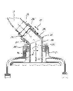
[0018] Referring to Figs. 3-5, it can be seen that the tube adapter 28 has a
tubular body
including a proximal end portion 28a adjustably connectable to the bearing
housing 24.
According to the illustrated embodiment, the proximal end portion 28a is
slidably
engaged in the opening of port 24a. However, it is understood that the
male/female
mating engagement between the proximal end 28a of the tube adapter 28 and the
bearing housing 24 could be reversed. A friction fit can be provided between
the
adapter 28 and the bearing housing 24 to allow the adapter 28 to temporarily
retain its
position relative to the bearing housing 24 while the installation procedure
is being
completed. A seal, such as a labyrinth seal 28d, can be provided between the
tube
adapter 28 and the bearing housing 24. According to some embodiments, the
labyrinth
seal 24 comprises an array of axially spaced-apart annular sealing fins
integrally formed
on an outer surface of the proximal end portion 28a of the tube adapter 28 for
sealing
engagement with an inner surface of the port 24a of the bearing housing 24.
Such a
4
Date Recue/Date Received 2021-05-14
sealing arrangement eliminates the need for 0-rings, which were typically used
at the
interface of the tube and the mating structural component (e.g. the bearing
housing)
despite the fact such 0-rings were prone to premature deterioration as their
maximum
operating temperature is at least in some instances less than the temperature
of the
interfacing structural component during some engine running conditions.
[0019] As illustrated in Fig. 3, the tube adapter 28 may have an elbow
configuration
including a distal end portion 28b projecting at an angle from the proximal
end portion
28a outwardly from port 24a. The distal end portion 28b has a central axis
28b'. As
depicted by arrows Al and A2, the exemplified adapter 28 has two degrees of
freedom
relative to the bearing housing 24. The first degree of freedom Al corresponds
to a
translation of the adapter 28 along the central axis 24c of the port 24a. The
second
degree of freedom A2 corresponds to a rotation of the adapter 28 about central
axis
24c. As can be appreciated from Figs. 3 and 4, the adapter 28 can, thus, be
translated
along axis 24c and rotated thereabout so as to bring the axis 28b' of the
adapter 28 in
alignment with the axis 26b' of the tube 26 (Fig. 4). This allows a "best fit"
of all
components while respecting the different installation vectors. It is
understood that the
tube adapter 28 could have more than two degrees of freedom to provide
additional
installation flexibility if need be.
[0020] Still referring to Figs. 3-5, it can be appreciated that the coupling
30 is adjustably
mounted to the distal end portion 28b of the tube adapter 28. The coupling 30
has at
least one degree of freedom. According to some embodiments and as depicted by
arrows A3 in Fig. 3, the coupling 30 is translatable along the central axis
28b' of the
distal end portion 28b of the adapter 28. In the embodiment illustrated in
Figs. 3-5, the
coupling 30 is provided in the form of a short sleeve slidably mounted over
the distal
end portion 28b of the adapter 28. However, it is understood that the
male/female
mating engagement between the coupling 30 and the adapter 28 could be
reversed.
Also, it is contemplated to threadably engage the coupling 30 to the distal
end portion
28b of the adapter 28. As shown in Fig. 5, once the axis 28b' of the distal
end 28b of
the adapter 28 has been aligned with the axis 26b' of the second end 26b of
the tube
26, the coupling 30 can be slipped over the aligned second end 26b of the tube
26 to
provide a slip-joint fitting arrangement between the adapter 28 and the tube
26. Again, it
Date Recue/Date Received 2021-05-14
is understood that the male/female mating engagement between the coupling 30
and
the tube 26 could be reverse. Also, it is contemplated to provide a threaded
connection
between the coupling 30 and the tube 26.
[0021] Once the coupling 30 has been properly engaged with the second end 26b
of
the tube 26 as shown in Fig. 5, brazing joints 32 are made to secure the
connection
between the tube 26, the coupling 30, the adapter 28 and the bearing housing
24.
Alternatively, the tube 26, the coupling 30, the adapter 28 and the bearing
housing 24
could be welded, soldered or otherwise suitably fixedly secured to one
another. It is
also contemplated to use different combination of any suitable securing
methods to
fixedly join all the components.
[0022] According to some embodiments, the tube installation procedure
generally
comprises joining the first end 26a of the tube to the engine case 20 using
appropriate
fittings. The second end 26b of the tube 26 is joined to the bearing housing
24 by first
installing the tube adapter 28 and the associated coupling 30 on the bearing
housing
24. The coupling 30 can be pre-mounted over the distal end portion 26b of the
tube
adapter 26 or installed thereon after the tube adapter 28 has been engaged
with the
bearing housing 24. The initial misalignment between the tube axis 26b' and
the axis
28b' of the distal end portion 28b of the pre-installed tube adapter 28 as
shown in Fig. 2
is corrected by adjusting the position of the tube adapter 28 so as to bring
the axes
26b', 28b' in alignment as shown in Fig 4. The adjustment of the position of
the tube
adapter 28 includes at least one of translating the tube adapter 28 along the
axis 24c of
the bearing housing port 24a as depicted by arrows Al and rotating the tube
adapter 28
about axis 24c as represented by arrow A2. As can be appreciated from Figs. 4
and 5,
any remaining gaps between the tube 26 and the tube adapter 28, which may be
due to
stack-up build up, is accommodated by the coupling 30. More particularly, the
coupling
30 can be extended from the distal end portion 28b of the tube adapter 28 so
as to
engage the second end 26b of the tube 26. According to the illustrated
example, the
coupling 30 is slipped over the second end 26b of the tube 26 by sliding the
coupling 30
on the tube adapter 28 in the direction depicted by arrow S in Fig. 5. Once
the tube
adapter 28 and the tube 26 have been joined together via the coupling 30, the
joint
components are secured all together. According to some embodiments, brazed
joints
6
Date Recue/Date Received 2021-05-14
32 are created to fixedly secure the tube 26, the coupling 30, the tube
adapter 28 and
the bearing housing 24 to one another. It is noted that the above installation
procedure
at the second end 26b of the tube 26 could be replicated at the first end 26a
of the tube
26 to connect the tube 26 to the engine case 20. Alternatively, the tube
adapter and the
coupling could be pre-installed on the engine case 20 and a conventional tube
fitting
could be provided at the second end 26b of the tube 26 for connection with the
bearing
housing 24. Various permutations are contemplated (e.g. separate tube adapter
28 and
coupling 30 at both ends of the tube 26, only at the first end or only at the
second end).
[0023] Fig. 6 illustrates another tube installation wherein the adapter-to-
tube joint is
parallel to the tube-to-case joint. More particularly, the first end 126a of
rigid tube 126 is
coupled to a first port 120a on the engine case 120. The first port has a
central axis
120b defining a first installation vector for the engagement of the first end
126a of the
tube 126 with the engine case 120 (tube-to-case joint). As shown in Fig. 6,
the first end
126a of the tube 126 is provided with a suitable fitting or end connection for
connection
with the first port 120a on the engine case 120. Likewise, the second end 126b
of the
tube 126 is provided with a suitable fitting or end connection for connection
with a
separate tube adapter 128 pre-installed in a mating port 124a on the bearing
housing
124. The tube adapter 128 is translatable in and out from the port 124a and
rotatable
about the axis of the port 124a to facilitate the connection of the tube 126
to the bearing
housing 124. The tube adapter 128 has a tubular distal end 128b having a
central axis
128b'. The axis 128b' of the tube adapter 128 defines a second engagement
vector for
the engagement of the adapter 128 with the second end 126b of the tube 126
(adapter-
to-tube joint). As can be appreciated from Fig. 6, the axis 128b' of the tube
adapter 128
and the axis 120b of the first port 120a are parallel to one another. This
allows the tube
126 to be installed into both joints simultaneously as there is no tangential
shift of axis
128b' resulting from the translation of the tube adapter 128 relative to the
bearing
housing 124 (the movement of the tube adapter 128 in the bearing housing port
124a is
not accompanied by a tangential movement). In some applications, where the
tube
installation is not affected due to stack-up build up, the parallel
arrangement of the joint
axes might even eliminate the need for a coupling, such as coupling 30 shown
in Figs.
3 to 5.
7
Date Recue/Date Received 2021-05-14
[0024] In accordance with at least some embodiments, the introduction of a
separate
tube adapter and coupling, where the adapter and coupling are pre-installed to
an
engine structure to which the tube is to be coupled allows the tube to be
installed along
different fitting's installation vectors at opposed ends of the tube. In
accordance with
some embodiments, the tube adapter and the coupling facilitate the
installation and the
alignment of the parts, thereby mitigating installation induces stresses.
[0025] In accordance with some embodiments, the adapter and coupling are first
pre-
installed into one end (example: bearing housing), which then facilitates the
installation
of the tube along the other fitting's installation vector. Before securing the
tube in place,
all components (tube, separate fitting, and coupling) have some degrees of
freedom.
This allows a "best fit" of all components while respecting the different
engagement
vectors as well as the related stack-up build up. Before the final securing
operation (e.g.
brazing operation), the coupling slides onto the tube forming a rigid tube
connection.
[0026] In view of the foregoing, it can be appreciated that at least some of
the
embodiments allow for a rigid tube installation that has two fittings with
different
engagement vectors with reduced installation stresses. The degree of freedoms
provided by the tube adapter and the coupling allow the assembly of parts in
constricted
engine spaces.
[0027] The embodiments described in this document provide non-limiting
examples of
possible implementations of the present technology. Upon review of the present
disclosure, a person of ordinary skill in the art will recognize that changes
may be made
to the embodiments described herein without departing from the scope of the
present
technology. For example, the tube adapter does not have to be straight. It can
have a
bend or two bends with cross drilling. Also, the tube could have more than two
ends
(e.g. a Y-shape tube). Furthermore, it is noted that the tube adapter and the
coupling
can be made from a different material that has better properties for that
specific
location, or a less expensive material than the material used for the tube.
While the tube
adapter and the coupling have been exemplified in connection with the tube-to-
bearing
housing joint, it is understood that a separate tube adapter and associated
coupling
could be pre-installed on the engine case as well to provide a similar
adjustable joint at
both ends of the tube. Yet further modifications could be implemented by a
person of
8
Date Recue/Date Received 2021-05-14
ordinary skill in the art in view of the present disclosure, which
modifications would be
within the scope of the present technology.
9
Date Recue/Date Received 2021-05-14