Note : Les descriptions sont présentées dans la langue officielle dans laquelle elles ont été soumises.
DOUBLE JOURNAL BEARING IMPELLER FOR ACTIVE DE-AERATOR
CROSS-REFERENCE TO RELATED APPLICATIONS
[0001] This application claims priority to US patent application 16/936,606
filed July 23,
2020, the entire contents of which are incorporated herein by reference.
TECHNICAL FIELD
[0002] The disclosure relates generally to lubrication systems of aircraft
engines and,
more particularly, to systems and methods used to separate air from oil
flowing in such
lubrication systems.
BACKGROUND
[0003] Aircraft engines, such as gas turbine engines, include a lubrication
system for
distributing a lubricating fluid, such as oil for instance, to portions of the
engine. This
lubricating oil may be directed to and from a bearing cavity of the aircraft
engine, for
example. Air may become mixed with the oil due to the compressed air used for
pressurizing the bearing cavity, and the amount of air in the lubricating oil
may thus
increase after the oil has been fed through the bearing cavity. A de-aerator
may be
used in the lubrication system to remove at least a portion of the air from
the oil. In use,
such de-aerator may be subject to rotor vibrations, for instance as a result
of the
turbulent flow of mixed oil and air flowing therethrough.
SUMMARY
[0004] In one aspect, there is provided an active de-aerator for an aircraft
engine,
comprising: a housing having an air-oil inlet, an oil outlet and an air
outlet; an impeller
received within and rotatable relative to the housing about a central axis; a
first journal
bearing on a first side of the impeller for rotatably supporting the impeller
relative to the
housing; and a second journal bearing on a second side of the impeller for
rotatably
supporting the impeller relative to the housing, the second side being
opposite the first
side.
CAN_DMS: \139383683\1 1
Date Recue/Date Received 2021-05-14
[0005] In another aspect, there is provided a lubrication system of an
aircraft engine,
comprising: a lubricant reservoir fluidly connected to lubrication conduits;
at least one
pump fluidly connected to the lubricant reservoir and the lubrication conduits
for
inducing a flow of lubricant within the lubrication conduits, the pump having
a housing
and a pump shaft mounted for rotation about a central axis within the housing,
the
housing defining an air-oil inlet, an oil outlet and an air outlet; and a de-
aerator having
an impeller received within and rotatable relative to the housing about the
central axis,
the impeller connected to the pump shaft for rotation therewith, a first
journal bearing on
a first side of the impeller for rotatably supporting the impeller relative to
the housing,
and a second journal bearing on a second side of the impeller for rotatably
supporting
the impeller relative to the housing, the second side being opposite the first
side.
[0006] In a further aspect, there is provided a method of mounting an active
de-aerator
to an oil pump, the active de-aerator having an impeller, the oil pump having
a pump
shaft mounted for rotation about a central axis within a housing, the method
comprising:
engaging an end of the pump shaft with a shaft connecting portion of the
impeller on a
first side of the impeller; engaging the shaft connecting portion of the
impeller within a
first portion of the housing, the shaft connecting portion and the first
portion of the
housing having surfaces facing each other adapted to receive a lubricant film
therebetween and defining a first journal bearing; and engaging a second
portion of the
housing with a flange wall of the impeller on a second side of the impeller
opposite the
first side, the flange wall of the impeller and the second portion of the
housing having
surfaces facing each other adapted to receive a lubricant film therebetween
and
defining a second journal bearing.
DESCRIPTION OF THE DRAWINGS
[0007] Reference is now made to the accompanying figures in which:
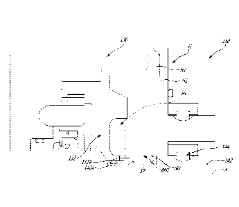
[0008] Fig. 1 is a schematic cross sectional view of an aircraft engine
provided in the
form of a gas turbine engine;
[0009] Fig. 1A is a schematic view of a lubrication system used with the
aircraft engine
of Fig. 1;
CAN_DMS: \139383683\1 2
Date Recue/Date Received 2021-05-14
[0010] Fig. 2 is a schematic cross-sectional view of an active de-aerator in
accordance
with an embodiment that may be used within a lubrication system of the
aircraft engine
of Fig. 1, the cross-sectional view taken along a central axis A of the active
de-aerator;
[0011] Fig. 3 is a perspective cross-sectional view of the active de-aerator
of Fig. 2, the
cross-section taken along a central axis A of the active de-aerator; and
[0012] Fig. 3A is another perspective cross-sectional view of the active de-
aerator as
Fig. 3, now with references to flow passages of the active de-aerator, the
cross-section
taken along a central axis A of the active de-aerator.
DETAILED DESCRIPTION
[0013] Fig. 1 illustrates an aircraft engine 10, such as a gas turbine engine,
of a type
preferably provided for use in subsonic flight. The gas turbine engine 10
generally
includes in serial flow communication a fan 12 through which ambient air is
propelled, a
compressor section 14 for pressurizing the air, a combustor 16 in which the
compressed air is mixed with fuel and ignited for generating an annular stream
of hot
combustion gases, and a turbine section 18 for extracting energy from the
combustion
gases. The fan 12, the compressor section 14, and the turbine section 18 are
rotatable
about a central axis 11 of the gas turbine engine 10.
[0014] Referring to Figs. 1 and 1A, the gas turbine engine 10 includes a
lubrication
system 100 that includes one or more pumps 102, lubrication conduits 104 that
form a
network of conduits, a lubricant reservoir 106, and a de-aerator 130. The
lubrication
system 100 may also include additional components such as valve(s), heat
exchangers,
filters, etc. The lubricant reservoir 106 is hydraulically connected to one or
more
components C of the engine 10 in need of lubrication, such as, for instance,
bearing
cavity(ies) 13, gearbox(es), and so on. The pump 102 is operable to induce a
flow of
the lubricant from the lubricant reservoir 106, to the one or more components
C of the
engine 10 in need of lubrication. A scavenge pump(s) 108 may be present and is
operable to draw a scavenge flow of oil back to the reservoir 106. The
scavenge pump
108 has an inlet hydraulically connected to a scavenge outlet Cl of the
component C
and an outlet hydraulically connected to the de-aerator 130. In some cases,
for instance
CAN_DMS: \139383683\1 3
Date Recue/Date Received 2021-05-14
when the component C is a bearing cavity 13, the oil flows through the bearing
cavity
13 and is mixed with compressed air injected therein for pressurizing the
bearing cavity
13. The oil mixture exiting the bearing cavity 13 may thus have a greater air
content
than the oil mixture entering the bearing cavity 13. The de-aerator 130 is
operable to
remove at least a portion of the air contained within the air-oil mixture it
receives before
flowing the oil back to the one or more components in need of lubrication. The
de-
aerator 130 has an air-oil inlet 130a hydraulically connected to the scavenge
outlet Cl
of the component C via the scavenge pump 108; an oil outlet 130b hydraulically
connected to the reservoir 106 for returning the de-aerated oil back to the
reservoir 106;
and an air outlet 130c hydraulically connected to a vent 110 for expelling the
air out to
an environment E outside of the gas turbine engine 10. It will be appreciated
that the
location of some of the parts of the lubrication system 100 (e.g., scavenge
pump 108,
pump 102, vent 110) may differ from what is illustrated in Fig. 1A. For
instance, the
scavenge pump 108 and the active de-aerator 130 may be integrally part of a
same
pumping system or pumping unit, with the flow passage in between them
illustrated in
Fig. 1A defined as part of the scavenge pump 108 and/or de-aerator 130.
[0015] Any suitable arrangement of the lubrication system 100 is contemplated.
The
de-aerator 130 may be included in any lubrication systems, such as those
discloses in
U.S. patent application no. 16/791,375, the entire contents of which are
incorporated
herein by reference.
[0016] Referring now to Figs. 2-3, an active de-aerator 130, which may operate
as the
de-aerator 130 in the lubrication system 100 of Fig. 1A, is illustrated
according to an
embodiment. The de-aerator 130 is an "active" de-aerator since it has at least
one
component (e.g., impeller) that is driven, such as by electrical and/or
pneumatic and/or
hydraulic or other means (motors, actuators, etc.). A de-aerator is different
than a de-
oiler. A de-oiler is typically located within a lubricated cavity (e.g., gear
box) and is
designed to remove oil (e.g., oil droplets/mist) within an air-oil mixture
before ejecting
air overboard. The de-aerator 130 is designed to extract air from an air-oil
mixture and
to feed oil back to the lubrication system 100. Typically, the de-oiler does
not include a
housing. In contrast, the housing of the de-aerator 130 is used to collect the
oil
extracted by centrifugation so that the extracted oil is flown back to the oil
system.
CAN_DMS: \139383683\1 4
Date Recue/Date Received 2021-05-14
Since the de-oiler is located within the lubricated cavity, it does not need a
housing and
the oil may simply be ejected via centrifugation against the components in
need of
lubrication contained within the lubricated cavity (e.g., gears).
[0017] In the depicted embodiment, and referring to Fig. 2, the active de-
aerator 130 is
driven by an oil pump 140. In the depicted embodiment the active de-aerator
130 is part
of the oil pump 140. In other words, the active de-aerator 130 is "built-in"
with the oil
pump 140, or retrofitted into the oil pump 140. Although shown in isolation in
Figs. 2-3,
the oil pump 140 and active de-aerator 130 may function as the scavenge pump
108
and de-aerator 130 schematically illustrated in Fig. 1A. In an embodiment, the
oil pump
140 driving the de-aerator 130 in Figs 2-3 may be a scavenge pump, such as
pump 108
of Fig. 1A.
[0018] As shown in Fig. 2, the oil pump 140 has a housing H receiving
components
forming parts of the active de-aerator 130. In other embodiments, the active
de-aerator
130 may be configured as a standalone device that is coupled to an oil pump,
or
coupled to any device able to generate a rotational input to the de-aerator
130 in yet
other embodiments. For instance, the rotational input may be provided by an
electric
motor, or a shaft of the gas turbine engine 10 (Fig. 1). As shown, the housing
H
includes a first housing section H1 and a second housing section H2 securable
to each
other. The first and second housing sections H1, H2 defines a cavity HC (best
seen in
Fig. 3). A seal(s) S may be provided at an interface between the first and
second
housing sections H1, H2 to limit leakage of fluid at the interface. In some
embodiments,
the cavity HC is a sealed cavity, with one or more inlets and outlets allowing
fluid flow
communication with the sealed cavity.
[0019] The oil pump 140 includes flow inducing means 144. In this embodiment,
the
flow inducing means 144 are intermeshing gears disposed within a flow path of
the
pump 140 and inducing fluid flow by mutual rotation. Depending on the pump,
one or
more flow inducing means may be mounted serially or in parallel with one
another to
form one or more pump stages. The flow inducing means (all or some) may be
mounted
to a pump shaft 142 for rotation therewith. As another example, the flow
inducing
means 144 are blades, etc.
CAN_DMS: \139383683\1 5
Date Recue/Date Received 2021-05-14
The active de-aerator 130 includes an impeller 132. The impeller 132 is
received within
the housing H and may rotate relative to the housing H about a central axis A.
[0020] The impeller 132 is enclosed within the cavity HC defined by the first
and
second housing sections H1, H2. The impeller 132 has a shaft connecting
portion 132a
that is drivingly engageable to the oil pump shaft 142 for receiving a
rotational input
therefrom. As shown, the shaft connecting portion 132a extends axially along
central
axis A, e.g., concentrically. As shown in Fig. 3, the shaft connecting portion
132a
defines an annular body protruding axially from a remainder of the impeller
132. The
shaft connecting portion 132a defines a hollow space SH having sections of
different
bore sizes sized to receive a complementary end of the pump shaft 142. Other
shapes
of hollow space for connecting with an end of the pump shaft 142 may be
contemplated. In the depicted embodiment, the shaft connecting portion 132a
and an
end 142a of the pump shaft 142 have complementary splines SP (see Fig. 2) for
mutual
axial engagement, as a possibility among others to rotatably couple them. The
shaft
connecting portion 132a and the end of the pump shaft 142 may thus be
drivingly
engaged to each other such that rotational input provided by the pump shaft
142 may
induce rotation of the impeller 132. The housing H, here housing section H1,
may
define a bore BH1 supporting the shaft connecting portion 132a. At least part
of the
shaft connecting portion 132a may be received within the bore BH1.
[0021] The impeller 132 has a rim 132b, which may be referred to as a ring
portion and
blades 132c that are circumferentially distributed around the central axis A.
The rim
132b extends circumferentially around the central axis A and around the blades
132c.
In the embodiment shown, the blades 132c are secured to a fore flange 132d
that is
secured to the shaft connecting portion 132a and to an aft flange 132e, e.g.,
they may
be a monoblock piece. Both of the first and second flanges 132d, 132e are
annular and
extend all around the central axis A. The fore flange 132d is used to redirect
a flow of oil
that enters the de-aerator 130 in a substantially axial direction relative to
the central
axis A to a substantially radial direction relative to the central axis A
before the flow of
oil meets the blades 132c. The blades 132c have radially inner ends 132f and
radially
outer ends 132g. In the embodiment shown, the radially outer ends 132g of the
blades
132c are secured to the rim 132b of the impeller 132. In the embodiment shown,
the
CAN_DMS: \139383683\1 6
Date Recue/Date Received 2021-05-14
blades 132c and the rim 132b are integral and are defined as a single part,
though
other constructions are possible. The radially inner ends 132f of the blades
132c are
located axially between the fore and aft flanges 132d, 132e.
[0022] The flow of mixed air-oil passing through the impeller 132 may be
turbulent and
may create uneven loads as a density of the oil or air within the mixture may
continuously vary over instant times. Such uneven loads may induce vibrations.
Vibrations and/or shaft impeller shaft deflection may be limited by proper
supporting
means and configuration within the housing H. In the depicted embodiment, a
periphery
of the shaft connecting portion 132a and a surface of the bore BH1 facing the
periphery
of the shaft connecting portion 132a define a journal bearing JB1. A film of
oil or other
lubricant may be present between the surface of the bore BH1 facing the
periphery of
the shaft connecting portion 132a and the periphery of the shaft connecting
portion
132a. The bore BH1 may thus be referred to as a portion of the housing H
supporting
the impeller 132 and/or as defining part of the journal bearing JB1. The
journal bearing
JB1 may be defined by a separate part interfacing with the bore BH1 and the
periphery
of the shaft connecting portion 132a in other embodiments. For instance, the
journal
bearing JB1 may be an annular insert slidingly engaged within the bore BH1,
which
may be replaced when worn out.The active de-aerator 130 has an inlet side I
and an
opposed outlet side 0, which may respectively be referred to as a fore side
and an aft
side. As opposed to being cantilevered from the end of the pump shaft 142, the
impeller
132 is further supported on the outlet side 0. As shown, the impeller 132 is
rotatably
supported within the housing H, here second housing section H2, via another
journal
bearing JB2. As discussed above, the bore BH1 and the shaft connecting portion
132a
of the impeller define the journal bearing JB2, which may be referred to as a
first journal
bearing for rotatably supporting the shaft connecting portion 132a of the
impeller 132 on
the inlet side I. The impeller 132 may thus be supported by a pair of journal
bearings
JB1, JB2 disposed respectively on the inlet and outlet sides I, 0 of the
impeller 132, as
opposed to being cantilevered to the pump shaft 142, for instance. The dual
journal
bearings JB1, JB2 mounting of the impeller 132 within the housing H may
increase
stability and/or reduce shaft deflection.
CAN_DMS: \139383683\1 7
Date Recue/Date Received 2021-05-14
[0023] The housing H, here the second housing section H2, defines a bore BH2.
In the
depicted embodiment, the bore BH2 is concentric with the bore BH1 discussed
above.
The bore BH2 is surrounded by an annular wall BHW. In the depicted embodiment,
the
second flange 132e defines a flange wall 132h extending axially along the
central axis
A. The flange wall 132h has a surface facing an outer periphery of the annular
wall
BHW. As shown, the journal bearing JB2 on the outlet side 0 of the impeller
132 is
defined by the flange wall 132h and the annular wall BHW. A film of lubricant
of the
journal bearing JB2, between the flange wall 132h and the annular wall BHW may
allow
lower friction to facilitate rotation. The bore BH2 may thus be referred to as
another
portion of the housing H supporting the impeller 132 and/or as defining part
of the
journal bearing JB2. Stated differently, the bores BH1, BH2 are two portions
of the
housing H that contribute to the support of the impeller 132 and that are
adapted to
allow rotation of the impeller 132 within the housing H.
[0024] The journal bearing JB2 may also be a separate part interfacing between
the
flange wall 132h and the annular wall BHW in other embodiments. For instance,
the
journal bearing JB2 may be an annular insert slidingly engaged around the
annular wall
BHW, which may be replaced when worn out.
[0025] The flange wall 132h may be located radially inwardly relative to the
annular wall
BHW in other embodiments, such that the journal bearing JB2 may be defined
between
an outer periphery of the flange wall 132h and an inner periphery of the
annular wall
BHW, for instance.
[0026] In the depicted embodiment, the journal bearings JB1, JB2 are delimited
(delimited or defined) by cylindrical (cylindrical or substantially
cylindrical) surfaces
facing each other. Also, as shown, such cylindrical surfaces are extending
substantially
in an axial direction along central axis A. The journal bearings JB1, JB2 may
be defined
by uneven surfaces and/or between surfaces angled (or "oblique") relative to
the central
axis A in other embodiments. For instance, the journal bearings JB1, JB2 may
be
conical when viewed in a cross-section as in Fig. 3.
[0027] The air-oil inlet 130a of the active de-aerator 130 is located on the
inlet side I;
and the oil outlet 130b and the air outlet 130c are located on the outlet side
0 of the de-
CAN_DMS: \139383683\1 8
Date Recue/Date Received 2021-05-14
aerator 130. In the embodiment shown, the air-oil inlet 130a, the oil outlet
130b, and the
air outlet 130c are defined by the housing H. In operation, for separating the
air from the
air-oil flow, the air-oil mixture is received via the air-oil inlet 130a of
the de-aerator 130
in a generally axial direction relative to the central axis A of the impeller
132. The
received air-oil flow is redirected in a radial direction relative to the
central axis A and
the air is separated from the air-oil flow by centrifugation within the
impeller 132. Stated
differently, oil is directed radially outward of the second flange 132e by
centrifugal
forces and follows the path to the oil outlet 130b. Air may on the other hand
follow the
more central path to flow instead to the air outlet 130c. The extracted air
may thus be
expelled out from the impeller 132 at a radially inward location relative to
the oil flowing
out from the impeller 132. The journal bearings JB1, JB2 are hydraulically
connected
with the air-oil inlet 130a and the oil outlet 130b, which may allow constant
lubrication of
the journal bearings JB1, JB2 in operation. Oil leaking from the journal
bearings JB1,
JB2 may thus be flushed with the air-oil mixture as the air-oil flow passes
through the
impeller 132 and/or flushed with the oil exiting the impeller 132 via the oil
outlet 130b.
Such dual journal bearings JB1, JB2 mounting of the impeller 132 may thus be
advantageous in the context of oil and/or air-oil environment, whereas such
dual journal
bearings JB1, JB2 mounting of impeller 132 may not be desirable in other
environment
without such oil or air-oil interaction.
[0028] The impeller 132 may further have a tube 132i connected to the second
flange
132e. As shown, the tube 132i is integral with the second flange 132e. The
tube 132i is
concentric with the central axis A. The tube 132i has an internal passage P4
which is
fluidly connected to the air outlet 130c. The separated air from the mixture
of air-oil may
thus be channeled through the tube 132i and expelled into the air outlet 130c.
The tube
132i defines an axial end of the impeller 132 that is opposite the shaft
connecting
portion 132a discussed above. The tube 132i is located on one axial side of
the blades
132c of the impeller 132, opposite to the axial side of the blades 132c where
the shaft
connecting portion 132a is located. In the depicted embodiment, at least part
of the tube
132i is radially aligned with the journal bearing JB2 along the central axis
A.
[0029] The tube 132i is received within the bore BH2. A seal(s), here a lip
seal LS,
interfaces with a periphery of the tube 132i and the wall BHW of the bore BH2.
As
CAN_DMS: \139383683\1 9
Date Recue/Date Received 2021-05-14
shown, the lip seal LS is secured between the outer periphery of the tube 132i
and an
inner periphery of the wall BHW. The lip seal LS may prevent or limit oil
leakage
through the air outlet 130c, which may in turn limit oil contamination of the
air outlet
130c and other components downstream thereof, if applicable. The lip seal LS
is
typically resilient and/or flexible to allow proper sealing at the interface
of opposite
surfaces (here radial surfaces). While the lip seal LS interfaces between the
tube 132i
and the wall BHW, it may not serve the function of radially supporting the
impeller 132,
as opposed to the journal bearings JB1, JB2 discussed above, as the lip seal
LS may
radially deflect, for instance as a result of its low radial rigidity and/or
its geometry. The
journal bearings JB1, JB2 typically allow for a limited radial deflection, as
a
consequence of the gap sized to allow a thin film of lubricant between the
journal
bearings surfaces. For instance, in an embodiment, a radial dimension of the
gap
and/or lubricant film is between 0.001 to 0.002 inch. Other types of seals may
be
contemplated in other embodiments.
[0030] In the depicted embodiment, the journal bearing JB2 is radially outward
relative
to the lip seal LS. The journal bearing JB2 is fluidly connected to the oil
outlet 130b
radially outward from the lip seal LS, while the lip seal Ls may prevent or at
least limit
interaction of the air flowing out from the impeller 132 through the tube 132i
with the
journal bearing JB2. The lip seal LS may thus act as a "air barrier" between
the tube
132i by which air may exit the impeller 132 and the journal bearing JB2. While
the
journal bearing JB2 is located between the outer periphery of the wall BHW and
the
inner periphery of the flange wall 132h in the embodiment shown, the journal
bearing
JB2 may be disposed at the location of the lip seal LS in other embodiments.
For
instance, the journal bearing JB2 in embodiments that are not shown herein may
be
between the outer periphery of the tube 132i and the inner periphery of the
wall BHW,
in series with the lip seal LS, if the lip seal LS is present in such
embodiments.
[0031] Referring to Fig. 3A, a plurality of flow passages P are defined
circumferentially
between each two circumferentially adjacent ones of the blades 132c. The flow
passages P have passage inlets P1 extending radially between a periphery of
the first
flange 132d and the rim 132b, extending circumferentially between each two
adjacent
ones of the blades 132c, and extending axially between the rim 132b and the
fore
CAN_DMS: \139383683\1 10
Date Recue/Date Received 2021-05-14
flange 132d. In the depicted embodiment, the inlets P1 of the flow passages P
face a
direction which has a radial component relative to the central axis A. In the
embodiment
shown, the radial component of the inlets P1 of the flow passages P is
oriented away
from the central axis A. The flow passages P have air outlets P2 proximate the
central
axis A. The air outlets P2 of the flow passages P are defined
circumferentially between
each of two adjacent ones of the radially inner ends 132f of the blades 132c
and axially
between the fore and aft flanges 132d, 132e.
[0032] The flow passages P further have oil outlets P3 located axially between
an axial
end of the rim 132b and the aft flange 132e. More specifically, a portion
132c1 of the
blades 132c extends radially beyond and curves around a radially outer edge of
the aft
annular flange 132e when viewed in a cross-section as in Fig. 3A. The portions
132c1
of the blades 132c that extend radially outwardly around the aft flange 132e
have
radially inner ends 132c2 that are located on a downstream side of the aft
flange 132e.
The oil outlets P3 are defined circumferentially between each two adjacent
ones of the
radially inner ends 132c2 of the portions 132c1 of the blades 132c.
[0033] The flow passages P further include the internal passage P4 defined by
the
hollow tube 132i. The internal passage P4 is fluidly connected to the air
outlets P2 of
the flow passages P defined between the blades 132c of the impeller 132.
[0034] In use, an air-oil mixture is received into the de-aerator 130 via the
air-oil inlet
130a along arrow Al. The oil is diverted radially outwardly away from the
central axis A
by the fore flange 132d. The oil is then divided between the flow passages P
upon
rotation of the fore flange 132d and enters those flow passages P via their
respective
inlets P1. The oil is then impinged by the blades 132c of the impeller 132.
Such
impingement may cause separation of the air contained in the air-oil mixture
from the
oil. The separated oil flows within the flow passages P defined between the
blades
132c, around the periphery of the second flange 132e along arrow A2 and exits
the flow
passages P via the oil outlet P3 defined axially between the aft flange 132e
and the rim
32b and circumferentially between the radially-inner ends 132c2 of the
portions 132c1
of the blades 132c that extend aft of the aft flange 132e. The oil then exits
the de-
aerator 130 via the oil outlet 130b thereof along arrow A3. As shown in Fig.
1A, the
extracted oil is then flown back to the reservoir 106, through which it is
circulated to the
CAN_DMS: \139383683\1 11
Date Recue/Date Received 2021-05-14
components (e.g., bearing cavity 13) in need of lubrication. The air extracted
from the
air-oil mixture flows around a periphery of the first flange 132d along flow
path A4,
moves radially inwardly toward the central axis A, and exits the flow passages
P via
their air outlets P2 defined circumferentially between the radially-inner ends
132f of the
portions of the blades 132c that are located between the fore and aft flanges
132d,
132e. The extracted air then flows into the passage P4 of the hollow tube 132i
along
arrow A5 and out of the de-aerator 130 via the air outlet 130c.
[0035] In the embodiment shown, the disclosed de-aerator 130 has solely two
outlets:
the oil outlet 130b and the air outlet 130c. In the present case, the de-
aerator 130 has
solely three connections to the oil system 100 (Fig. 1A), that is the air-oil
inlet 130a, the
air outlet 130c, and the oil outlet 130b, and is free of other connections to
the oil system
100.
[0036] The embodiments described in this document provide non-limiting
examples of
possible implementations of the present technology. Upon review of the present
disclosure, a person of ordinary skill in the art will recognize that changes
may be made
to the embodiments described herein without departing from the scope of the
present
technology. Yet further modifications could be implemented by a person of
ordinary skill
in the art in view of the present disclosure, which modifications would be
within the
scope of the present technology.
CAN_DMS: \139383683\1 12
Date Recue/Date Received 2021-05-14