Note : Les descriptions sont présentées dans la langue officielle dans laquelle elles ont été soumises.
1
VEHICLE ODOMETRY AND MOTION DIRECTION DETERMINATION
RELATED APPLICATIONS
[0001] This application claims priority to U.S. Provisional Patent Application
No. 62/779,949, titled
"VEHICLE ODOMETRY AND MOTION DIRECTION DETERMINATION USING COTS
RADAR" and filed on December 14, 2018.
BACKGROUND
[0002] Vehicle management includes determinations of vehicle odometry and
motion direction. The
need to manage vehicle odometry and motion direction is amplified in a mass-
transit vehicle environ.
Vehicle odometry includes the ground speed the vehicle is moving on the road
or the rails and the
distance the vehicle travelled along the road/rails since start up or with
respect to a known landmark.
Motion direction determinations inform vehicle management of which end of
vehicle is leading and
which direction the vehicle is moving.
BRIEF DESCRIPTION OF THE DRAWINGS
[0003] Figure 1 is a simplified representation of "motion direction" in
accordance with some
embodiments.
[0004] Figure 2 is a top-view diagram of a vehicle odometry and motion
direction system, in
accordance with some embodiments.
[0005] Figure 3 is a top-view and side-view diagram of a vehicle odometry and
motion direction
system, in accordance with some embodiments.
[0006] Figure 4 is a histogram of the distribution of targets versus speed, in
accordance with some
embodiments.
[0007] Figure 5 is a diagram for determining ground speed, in accordance with
an embodiment.
[0008] Figure 6 is a table showing vehicle motion direction determinations, in
accordance with some
embodiments.
Date Regue/Date Received 2022-09-20
CA 03120498 2021-05-19
WO 2020/121286
PCT/162019/060865
2
[0009] Figure 7 is a flowchart of a method of speed determination, in
accordance with some
embodiments.
[0010] Figure 8 is a graph of the calibration scaling factor, in accordance
with some
embodiments.
[0011] Figure 9 is the system architecture of a vehicle odometry and motion
direction system
in the context of a rail vehicle, in accordance with some embodiments.
[0012] Figure 10 is a diagram depicting two scenarios of vehicles moving "in
concert", in
accordance with some embodiments.
[0013] Figure 11 is a flowchart for a method with multiple sensors, in
accordance with some
embodiments.
[0014] Figure 12 is a table showing the result of nine cases, in accordance
with some
embodiments.
[0015] Figure 13 is a table showing the result of nine cases, in accordance
with some
embodiments.
[0016] Figure 14 is a table showing the minimum viable sensors set, in
accordance with some
embodiments.
[0017] Figure 15 is a table depicting the viable sensors, in accordance with
some embodiments.
[0018] Figure 16 is a high-level block diagram of a processor-based system
usable in
conjunction with one or more embodiments.
CA 03120499 2021-05-19
WO 2020/121286
PCT/IB2019/060865
3
DETAILED DESCRIPTION
[0019] The following disclosure provides many different embodiments, or
examples, for
implementing different features of the provided subject matter. Specific
examples of
components, values, operations, materials, arrangements, etc., are described
below to simplify
the present disclosure. These are, of course, merely examples and are not
intended to be
limiting. Other components, values, operations, materials, arrangements,
etc., are
contemplated. For example, the formation of a first feature over or on a
second feature in the
description that follows may include embodiments in which the first and second
features are
formed in direct contact, and may also include embodiments in which additional
features may
be formed between the first and second features, such that the first and
second features may
not be in direct contact. In addition, the present disclosure may repeat
reference numerals
and/or letters in the various examples. This repetition is for the purpose of
simplicity and clarity
and does not in itself dictate a relationship between the various embodiments
and/or
configurations discussed.
[0020] Further, spatially relative terms, such as "beneath," "below," "lower."
"above," "upper"
and the like, may be used herein for ease of description to describe one
element or feature's
relationship to another element(s) or feature(s) as illustrated in the
figures. The spatially
relative terms are intended to encompass different orientations of the device
in use or operation
in addition to the orientation depicted in the figures. The apparatus may be
othenvise oriented
(rotated 90 degrees or at other orientations) and the spatially relative
descriptors used herein
may likewise be interpreted accordingly.
[0021] Figure us a simplified representation 100 of a vehicle on a track or
road to demonstrate
"motion direction". A vehicle 102 has a first end 104 (end A) and a second end
106 (end B).
The vehicle 102 moves along a guideway 108. The guideway 108 is train tracks,
in accordance
with an embodiment, or other forms of guideway such as rails, concrete
viaduct, monorails, or
roads. The vehicle 102 moves in a first motion direction, motion direction A
110, or in a second
motion direction, motion direction B 112. "Motion direction" is used to
encompass a situation
when end A 104 of the vehicle is leading, the "motion direction" of the
vehicle is determined
to be motion direction A 110. When end B 106 of the vehicle is leading, the
"motion direction"
of the vehicle is determined to be motion direction B 112.
CA 03120499 2021-05-19
WO 2020/121286
PCT/162019/060865
4
[0022] Figure 2 is a top-view diagram of a vehicle odometry and motion
direction system 200,
in accordance with an embodiment. A vehicle 202 includes a radar 203 having a
radar field of
view (FOV) 204. A region of interest (ROI) 206 is in front of an end of the
vehicle 202, at a
distance of about five meters. In some embodiments, the ROI 206 is farther or
closer to the end
of the vehicle 202. The ROI 206 has a length of about ten meters. In some
embodiments, the
ROI 206 has a length longer or shorter than ten meters. The vehicle 202 moves
along rails 208.
In some embodiments, the vehicle 202 moves along a predetermined path.
[0023] The vehicle odometry and motion direction system and method, in
accordance with an
embodiment, provides confirmation that the ground speed, initialized based on
the radar 203,
is correct and not influenced by moving objects within the radar FOV 204 or
ghost objects
"detected" by the radar 203.
[0024] The vehicle odometry and motion direction system and method, in
accordance with an
embodiment, provides confirmation that stationary objects within the defined
ROI 206 are used
to determine the ground speed and that the determined speed is not influenced
by moving
objects within the radar FOV 204 or ghost objects "detected" by the radar 203.
[0025] The ROI 206 is a rectangular-shaped area within the FOV 204, as
depicted by the solid
line 210, in accordance with an embodiment. The ROI 206 is a section of the
FOV 204 with
which the boundaries partially overlap with the ROI 206, as depicted by the
dashed line 212,
in accordance with an embodiment.
[0026] A ghost target is a real object having an incorrect reported (by the
radar 203) position
within the radar FOV 204 or is a non-existing object that is reported by the
radar 203 as if it
was a real object. Ghost targets result from multipath propagation of the
electromagnetic
waves, total reflection "through" walls, radial distance and speed ambiguity,
multiple
propagation, the existence of high radar cross-section object or objects
outside of the FOV 204.
[0027] The ROI 206 is a construct from the distance to the ROI start point
(e.g., 5m) to the
ROI length (e.g., 10m). The ROI is a set of software defined parameters. The
ROI 206 is
contained within the radar's FOV 204, considering the minimum and maximum
ranges of the
FOV 204.
[0028] In accordance with an embodiment, the ROI start point and length is
selected to avoid
situations where the ROI start point starts too far away from the vehicle and
the ROI length is
CA 03120499 2021-05-19
WO 2020/121286
PCT/162019/060865
too large resulting in the ROI 206 "spilling" into the neighboring tracks
especially if the tracks
208 are curved. If the ROI start point is too close to the vehicle 202 or the
ROI length is too
short, the number of available targets that are accepted as valid targets for
the odometry
function is reduced.
[0029] Figure 3 is a top-view and side-view diagram of a vehicle odometry and
motion
direction system 300, in accordance with an embodiment. A vehicle 302 with a
radar 304
mounted at one end detects a first landmark 306, a second landmark 308 and a
target 309 as
the vehicle moves along a guideway 310.
[0030] The radar's Doppler speed transformation to ground speed by the vehicle
odometry and
motion direction system and method, in accordance with an embodiment, is
verified based on
comparing the calculated distance travelled, based on the radar's
measurements, between two
landmarks 306,308 with known location (Ea x VD,vpier x At) to the distance
between these two
landmarks 306, 308 as stored in the database. a is the transformation function
converting the
Doppler speed (VDoppier) measured by the radar to ground speed.
[0031] The radar 304 is installed on the "front" face of the vehicle 302 or at
any other location
on the vehicle 302 with good visibility towards the rails/road 310. The radar
elevation above
the track bed is h. The radar offset from the vehicle centreline is 1. The
radar tilt angle is 9.
[0032] The data received from a single radar on-board the vehicle is processed
to generate the
vehicle's ground speed and motion direction. The motion direction is
determined based on the
radar's Doppler speed sign and the radar association (in the vehicle database)
with A end 104
or B end 106 of a vehicle.
[0033] For a radar installed "facing out" on A end 104 of the vehicle, the
Doppler speed will
be negative if the vehicle's speed direction is from B end 106 to A end 104
(forward direction),
otherwise if the vehicle's speed direction is from A end 104 to B end 106
(reverse direction)
the radar's Doppler speed will be positive.
[0034] For the radar installed "facing out" on B end 106 of the vehicle, the
Doppler speed will
be positive if the vehicle's speed direction is from B end 106 to A end 104
(forward direction),
otherwise if the vehicle's speed direction is from A end 104 to B end 106
(reverse direction)
the radar's Doppler speed will be positive.
6
[0035] The target or targets Doppler speed provided by the radar is converted
into ground speed. This
step is based on geometry transformation between the radar frame of reference
and the vehicle's frame
of reference as described in Thales US patent application 15/247,142.
[0036] Figure 6 is a table showing vehicle motion direction determinations.
When the Doppler speed
sign is positive at vehicle end A, the motion direction is reverse. When the
Doppler speed sign is
positive at vehicle end B, the motion direction is forward. When the Doppler
speed sign is negative at
vehicle end A, the motion direction is forward. When the Doppler speed sign is
negative at vehicle end
B, the motion direction is reverse.
[0037] The relative speed between the radar 304 and the targets within the
radar's FOV 312 is
measured to non-moving stationary targets 309 residing on the "ground plane"
which is the road or the
track bed 310. The relative speed to targets within the radar's FOV 312 is the
vehicle's ground speed
component along the Line-of-Sight to these targets 309.
[0038] The calculated ground speed is accepted if it is based on target 309
that resides within a certain
envelope (Region of Interest or ROI) determined by the minimum range, maximum
range, the radar
tilt angle 0, minimum RCS etc.,
[0039] The maximum and minimum ranges are determined based on the radar's tilt
angle 0, the radar's
elevation above the track bed h and the radar's vertical FOV.
[0040] At certain locations a pair of landmarks 306, 308 such as
retroreflectors are installed with a
known distance between the landmarks. The purpose of the landmarks pair 306,
308 is to calibrate the
ground speed based on known ground truth distance. The landmarks 306, 308 are
installed in such a
way that the radar 304 will be able to detect both landmarks at the same time.
The radar 304 measures
the range to the first landmark 306 as R1 and to the second landmarks 30 as
R2.
[0041] In the vehicle odometry and motion direction system and method, in
accordance with an
embodiment, a COTS radar 304 that is capable of providing the following
measurements and their
related attributes is used. The radar 304 determines the range to each target
within the radar's Field-
of-View (FOV) 312. The radar 304 determines the relative radial speed to each
target within the radar's
Field-of-View (FOV) 312. The radar 304 deteimines each target angular position
within the radar's
Field-of-View (FOV) 312. In accordance with an
Date Regue/Date Received 2022-09-20
CA 03120499 2021-05-19
WO 2020/121286
PCT/162019/060865
embodiment, the radar 304 determines the azimuth angle (13). In some more
advanced radars,
the radar determines the elevation angle (X). The radar 304 determines each
target Radar Cross
Section (RCS). The radar 304 determines the range measurement error (the
standard deviation)
for each target 310. The radar determines the relative radial speed
measurement error (the
standard deviation) for each target 310. The radar 304 determines the azimuth
angle (and if
applicable elevation angle too) measurement error (the standard deviation) for
each target 310.
[0042] Target 310 is a reflective object that resides within the radar's FOV
312 and echoes the
RF waves emitted by the radar 304. In accordance with an embodiment, the
target 310 is a
retroreflector that its echo propagates along the same line but opposite
direction as the RF
waves propagation from the radar 310. In accordance with an embodiment, the
target 310 is a
"diffused surface" type object with echoes propagating in any direction.
[0043] The COTS radar 304, in accordance with an embodiment, is a frequency
modulated
continuous wave radar, a standard radar in the automotive market, or other
suitable types of
radar.
[0044] Tthe calculated ground speed for all targets reported by the radar in
every application
cycle regardless if it passed the ROI check (or not) goes through statistical
filtering process
based on a histogram.
[0045] In each radar application cycle, at least n targets are reported. In
accordance with an
embodiment, n >10.
[0046] Figure 4 is a histogram of the distribution of targets versus speed, in
accordance with
an embodiment. The SPEED_BIN_SIZE parameter defines the speed range for each
speed bin.
This parameter is constant or varies for each speed bin. The value set for
this parameter takes
into account the thresholding criteria between multiple speed groups
representing different
objects within the radar's FOV. For example, objects on the track bed that are
stationary and
moving objects such as vehicle or vehicles moving on the neighboring tracks.
[0047] The ground speed candidates will be determined to the average speed of
all targets
within the bin with the most number of targets, the bin with the second most
number of targets,
and the bin with the third most number of targets.
CA 03120499 2021-05-19
WO 2020/121286
PCT/162019/060865
8
[0048] The standard deviation of these speed candidates is determined. Then
statistical tests
will be applied to confirm that using t-test method or equivalent are the
speeds calculated based
on these bins independent or not, that using p-test method or equivalent are
the speeds
calculated based on these bins normally distributed or not.
[0049] The speed measured by the radar relative to an object or group of
objects moving at the
same speed (including stationary objects) is expected to be normally
distributed. Speeds
measured by the radar relative to objects moving at different speeds are
expected to be
independent variables while speeds measured by the radar relative to an object
or group of
objects moving at the same speed are expected to be dependent.
[0050] For each of these bins X1 is determined to the ratio of the number of
targets in the speed
bin (m) to n (the number of reported targets). Xi is a positive number between
zero and I. For
each of these bins the speed standard deviation (cri) is expected to be within
a certain predefined
bounds to ensure the validity of the determined speed. In accordance with an
embodiment, a;
is expected to be in the range from 0.01m/sec to 0.05m/sec.
[0051] Figure 5 is a diagram for determining ground speed, in accordance with
an
embodiment. The outcomes of accepting the calculated ground speed using an ROI
check and
the statistical filtering process determining the histogram bin with the three
largest number of
targets are processed to determine the ground speed. The whole and complete
set of targets
observed by the radar is n. The set of radar targets within the ROI is m; m
forms a subset of n.
The set of radar targets within speed bin i (Ens = n) is ni. The # of radar
targets within speed
bin i that are also within the ROI is m ROI (Eni ROI = m).
[0052] A check is performed to verify how many out of the speed measurements
that are in
each of these bins (m) satisfies the ROI check above (ni Rol).
[0053] The ratio X2 = ni ROI / n is calculated.
[0054] The number of targets that successfully passed the ROI check is
determined (m).
100551 The ratio X3 = n / m is calculated.
[0056] The ratio Xet = ROI / m is calculated.
[0057] The ratio X5 = n is calculated.
CA 03120498 2021-05-19
WO 2020/121286
PCT/162019/060865
9
[0058] The total number of targets is recalculated using X6 =
[0059] The number of targets within the ROI is recalculated using X7 = ZILT ni
ROI.
[0060] X6 is expected to be equal to n and X7 is expected to be equal to m.
[0061] Figures 12 and 13 are, taken together, a table showing the result of
nine cases, in
accordance with an embodiment.
[0062] The tables show the conditions, which when satisfied, indicate that the
ground speed
calculated based on the radar is trusted; and the conditions, which if
satisfied, indicate that the
ground speed calculated based on the radar is not trusted.
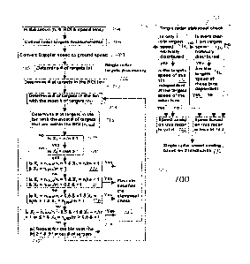
[0063] Figure 7 is a flowchart of a method of speed determination 700, in
accordance with an
embodiment. A single radar target processing step 702 proceeds to a single
rAdar statistical
check 732 resulting in a single radar speed scaling based on two landmarks
746. The single
radar target processing step includes an initialization step 704. Radar target
measurements are
collected in step 706. The Doppler speed is converted to ground speed data in
step 708. The
number of targets n is determined in step 710. The number of targets m within
the ROI is
determined in step 712. Then the number of targets ni in the bin with the
greatest number of
targets is determined in step 714. The number of targets (ni Rol) in the bin
with the greatest
number of targets that are within the ROI is determined in step 716. The
method, in step 718,
then checks to see if the ratio of the number of targets the bin with the
greatest number of
targets in the ROI to the total number of targets is less than or equal to
one. (Is Xi = n / n
1?)
[0064] If Xi is less than or equal to one, then the method, in step 720,
determines if the ratio
of the number of targets in the ROI to the total number of targets is less
than or equal to one.
(Ts X5 = M n <= 1?)
[0065] If either Xi or X5 is not less than or equal to I, then the process is
repeated for the bin
with the 2' and 3rd greatest number of targets in step 730.
[0066] If both X1 and X5 are less than or equal to I, the method, in step 722,
determines if the
ratio of the number of targets (ni ao0 in the bin with the most number of
targets that are within
the ROI to the number of targets (ni) in the bin with the most number of
targets is equal to one
and if the ratio of the number of targets (ni) in the bin with the most number
of targets to the
CA 03120499 2021-05-19
WO 2020/121286
PCT/1132019/060865
number of targets in the ROI (m) is equal to one and if the ratio of the
number of targets (iii) in
the bin with the most number of targets to the number of targets in the ROI
(m) is equal to one.
(Is X2 = Rod = 1 & X3= n; / m = 1 and X4= ni Roa m = 1?). If so, the first bin
satisfies the
statistical check in step 731. The process is then repeated for the bin with
the second and third
greatest number of targets in step 730.
[0067] If the equalities in step 722 fail, the method, in step 724 determines
if the ratio of the
number of targets (% Rol) in the bin with the most number of targets that are
within the ROI to
the number of targets (ni) in the bin with the most number of targets is equal
to one and if the
ratio of the number of targets (n0 in the bin with the most number of targets
to the number of
targets in the ROI (m) is less than one and if the ratio of the number of
targets (ni) in the bin
with the most number of targets to the number of targets in the ROI (m) is
greater than .5 and
less than one. (Is X, ni Rol / ni = 1 & X3 = / m < 1 and X4 = Rot/ m > .5 and
< 1?). If so,
the first bin satisfies the statistical check in step 731.
[0068] If the equalities in step 724 fail, the method, in step 726 determines
if the ratio of the
number of targets (n; Rol) in the bin with the most number of targets that are
within the ROI to
the number of targets (m) in the bin with the most number of targets is
greater than .5 & less
than one and if the ratio of the number of targets (m) in the bin with the
most number of targets
to the number of targets in the ROI (m) is greater than one and if the ratio
of the number of
targets (ni) in the bin with the most number of targets to the number of
targets in the ROI (m)
is equal to one. (Is X2 = ni RO1 ni > .5 & < 1 & X3 = n / m> 1 and X4 = Rot/ m
= 1?). If so,
the first bin satisfies the statistical check in step 731.
[0069] If the equalities in step 726 fail, the method, in step 728 determines
if the ratio of the
number of targets (ni ROI) in the bin with the most number of targets that are
within the ROI
to the number of targets (ni) in the bin with the most number of targets is
greater than .5 & less
than one and if the ratio of the number of targets (ni) in the bin with the
most number of targets
to the number of targets in the ROI (m) is greater than one or less than or
equal to one and if
the ratio of the number of targets (ni) in the bin with the most number of
targets to the number
of targets in the ROI (m) is greater than .5 and less than one. (Is X2 = n ROI
/ n > .5 & < 1 &
X3= / M > 1 or </ 1 and X4= ni ROI / m > .5 & <1?). If so. the first bin
satisfies the statistical
check in step 731.When the single radar targets processing in step 702 is
completed, the method
proceeds to the single radar statistical check in step 732. In step 734, the
method determines if
one bin targets speed is normally distributed.
CA 03120499 2021-05-19
WO 2020/121286
PCT/162019/060865
11
[0070] If one bin targets speed is normally distributed in step 734, the
method, in step 738,
determines if the targets speed of the bin is independent of the targets speed
of the other bins.
If the targets speed of the bin is not independent of the targets speed of the
other bins in step
738, the speed based on this radar, such as radar 304 in Figure 3, is invalid
in step 744. If the
targets speed of the bin is independent of the targets speed of the other bin
in step 738, the
speed based on this radar is valid in step 742.
[0071] If one bin targets speed is not normally distributed in step 734, the
method, in step 736,
determines if more than one bin targets speed is normally distributed. If more
than one bin
targets speed is not normally distributed in step 736, the speed based on the
radar is invalid in
step 744. If more than one targets speed is normally distributed in step 736,
the method, in step
740, determines if the targets speed of these bins are dependent. If the
targets speed of the bins
are not dependent in step 740, the speed based on this radar is invalid in
step 744. If the targets
speed of these bins are dependent, the speed based on this radar is valid. The
results are then
used to determine single radar speed scaling based on two landmarks is
performed in step 746.
1.0072] Using the t-test method or equivalent and the p-test method or
equivalent as described
in steps 718-731, applied to the bins, the bin or bins that are the best
representation of the
ground speed is determined.
[0073] For example, the bin or bins that has normally distributed speed and
its speed matches
the speed determined based on the ROI check.
[0074] In some cases, determining which bin is the best representation of the
ground speed is
difficult. For example, if all speed bins described above, or at least two of
them, have normally
distributed speed and the speed calculated based on each bin is independent
from each other,
then the outcome is inconclusive and additional information is needed to
resolve the situation.
[0075] The ground speed requires further scaling adjustment due to errors in
the conversion
from the Doppler speed to the ground speed.
[0076] At certain locations a pair of landmarks such as retroreflectors are
installed with a
known distance between the 2 landmarks. The purpose of the landmarks pair is
to calibrate the
ground speed based on known ground truth distance.
CA 03120499 2021-05-19
WO 2020/121286
PCT/162019/060865
12
[0077] The 2 landmarks will be installed in such a way that the radar will be
able to detect both
landmarks at the same time. The radar, such as radar 304 in Figure 3, measures
the range to
both landmarks (Ri & R2 in Diagram 4). The distance to each landmark is
determines as in
Equations 1 and 2.
Equation (1) d1 = (R12 - h2)1/2
Equation (2) d2 = (R22 - h2)1/2
[0078] The system will check that the difference between di and (I, matches d
(the distance
between the two landmarks) within a specified tolerance as shown in the
Equation below.
Equation (3) Absolute(Absolute(di - d2) - d) < dCheclong Tolerance
[0079] dChecking Tolerance is determined based on the landmarks installation
tolerance
(Landmarkinstanatinn ennr), the radar range measurement error (R1A---thiro---
õange Error), the radar height
above track bed installation error (hEnor) plus some predefined margin
(Admargin) as shown in
Equation 4.
Equation (4) de'h.-,..ecking Tolerance = LandlnarkInstallation Error +
(Rada!'Range Error2 hError2)1/2 Adhlargin
[0080] If the check according to Equation (3) above is passed the
transformation from the
Doppler speed measured by the radar (VDoppier) to the vehicle Ground speed
(VG) is scaled
according to Equations 5, 6, 7 and 8.
Equation (5) ai = Adi n Elg (V1 Doppler / cos(sin ¨ 1(h/R1))) x At
Equation (6) a2 = M2 n / /tt3(l/2 Doppler / cos(sin ¨ 1(h / R2))) x At
Equation (7) Adi n = Absolute(di in - di to)
Equation (8) Ad2 n = Absolute(d2 tn - d2 to)
[0081] d, tn is the distance to landmark I calculated based on the radar range
measurement at
time tn.
[0082] di to is the distance to landmark I calculated based on the radar range
measurement at
time to.
CA 03120499 2021-05-19
WO 2020/121286
PCT/162019/060865
13
[0083] d2 t8 is the distance to landmark 2 calculated based on the radar range
measurement at
time tn.
[0084] d2 to is the distance to landmark 2 calculated based on the radar range
measurement at
time to.
[0085] The scaling factor (a) is determined to be the average between al and
a2.
[0086] To verify the integrity of the above calculations at any point in time
the absolute value
of the difference between di and d2 (di - d2) matches the criteria defined in
Equation (3) above
as shown in Equation 9.
Equation (9) Absolute(Absolute(di to - d2 to) - d) < dalecking Tolerance
[0087] The absolute value of difference between Adi and Ad, (Adi - Ad2)
satisfies Equation
10.
Equation (10) Absolute (Adi n - Ad28) = Absoluteadi ca - di tn-1) (12 tn d2 tn-
1)) < datecking Tolerance
[0088] Figure 8 is a graph of the calibration scaling factor. The calibration
scaling factor a is
a function of the target vertical orientation within the radar's FOV (9= sin-
1(h/R)). To reduce
the influence of 0 on a t radar targets ate accepted, in the context of the
odometry function,
when the range satisfies Equation 1.
Equation (11) Rwon <R < Rmax or alternatively &din <d <dMax
[0089] For example, Rmin = 10m and Riviax = 20m.
[0090] The target inclination angle, with respect to the local horizon, is
approximately the ratio
of the radar elevation above the ground plane (h) and the range to the target
(R). In the context
of the pair of calibration landmarks, the method in accordance with one or
more embodiments
of this invention suggests to track these pair of landmarks if the range to
the landmark is greater
than the minimum and less than the maximum. When the vehicle approaches the
pair of
landmarks, the landmarks will be tracked if they are within the range window.
[0091] The greater the range thresholds, a will be less sensitive to 0.
However, the likelihood
of the speed determined based on the radar being influenced by moving objects
within the
CA 03120499 2021-05-19
WO 2020/121286
PCT/162019/060865
14
radar's FOV is greater too. The selection of Rm. and Rmax balances between
these two factors;
the sensitivity of a to 0 and the likelihood that the radar target is a moving
target.
[0092] The landmarks are installed in certain stopping locations such as in
platforms where the
vehicle is intended to stop to off-load passengers and to board new
passengers. In this case, the
process described above is performed while the vehicle is stationary (not
moving) to confirm
that the vehicle is aligned with the platform.
[0093] During the time period from to to t. both landmarks are observed by the
radar.
[0094] Single nidar system are not able to determine the correct vehicle speed
when the radar
measures the relative speed to multiple objects which are moving at different
speeds. To resolve
this situation, the ground speed calculated based on the single radar is
checked against the speed
determined based on another diverse sensor which uses different and
independent measurement
technology to determine the ground speed and the speed determined based on
other radar on-
board the vehicle, if available.
[0095] In accordance with various embodiments, the diverse sensor that uses
another diverse
and independent measurement technology to determine the ground speed is a body
mounted
IMU with 3-D accelerometer and 3-D gyroscope, a wheel/axle mounted
accelerometer array
(single axis or multi axis), an optical tachometer, a Hall effect speed
sensor, a LiDAR, a
Visible/IR spectrum camera or any other suitable sensor.
[0096] The vehicle odometry and motion direction system and method, in
accordance with an
embodiment, reduces the probability of incorrect ground speed determined based
on single
radar measurements due to environmental conditions, "Ghost" targets or moving
objects within
the radar's FOV to an acceptable level. In some embodiments, an acceptable
level is below a
predetermined threshold level.
[0097] The vehicle odometry and motion direction system and method, in
accordance with an
embodiment, provides calibration of single radar measurements against pair of
landmarks with
known distance between the two (2) landmarks.
[0098] The vehicle odometry and motion direction system and method, in
accordance with an
embodiment, provides high safety integrity level (SIL level 4) ground speed
determination
function with "non-simple" sensors such as, but not limited to, radar and
another diverse sensor
CA 03120499 2021-05-19
WO 2020/121286
PCT/182019/060865
based on different and independent measurement technology without "deep"
analysis of the
sensors internal failure modes (FMEA).
[0099] The two sensors (i.e. COTS radar and diverse sensor") are based on
completely
different non-overlapping sensing technologies.
[0100] The probability of these two sensors being influenced by environment or
any common
cause failure related to environment of or random failure is negligible to
improbable.
[0101] The speed calculation method based on the COTS radar measurements and
the speed
calculation method based on the diverse sensor measurements are completely
different
mathematically and based on completely different algorithms.
[0102] "In agreement" indicates that the speed calculated based on the COTS
radar
measurements and the speed calculated based on the diverse sensor measurements
match
within a predefined tolerance. On top of the two sensors being completely
different and non-
overlapping including their associated algorithms the safety bag argument
allows the speed
determined based on one of the sensors (either the COTS radar or the diverse
sensor) to be
more accurate than the other sensor while the other sensor (either the diverse
sensor or the
COTS radar) being less accurate but "encapsulating" the other sensor within a
certain envelope.
In this way the ground speed determined by the proposed method is trusted with
high
confidence level satisfying the integrity level requirement.
[0103] For an over-speed protection device) to be rated as Safety Integrity
Level (SIL) 4, the
over-speed protection device is required to have demonstratable on-demand
reliability. SIL 4
is based on International Electrotechnical Commission's (IEC) standard IEC
61508. SIL 4
requires the probability of failure per hour to range from 10-8 to 10-9.
[0104] For railway applications, an acceptable level of incorrect ground speed
determined by
the SIL 4 system is from 104 to 104 per operating hour. In accordance with an
embodiment,
the minimum viable sensor set for determining the ground speed is two (2)
sensors which use
diverse and independent measurement technologies. The product of the 2 sensor
errors satisfies
the Equation 12.
Equation (12) Pinoarrect Speed = Plncorrect Speed Radar X Plncorrect Speed
Diverse Sensor
CA 03120499 2021-05-19
WO 2020/121286
PCT/182019/060865
16
[0105] In the vehicle oclometry and motion direction system and method, in
accordance with
an embodiment, as long as the COTS radar and the diverse sensor measurement
technologies
are non-overlapping and the algorithms used to calculate the speed based on
the COTS radar
and the diverse sensor are completely different, failure to meet the
acceptable level of incorrect
ground speed, of the COTS radar alone or the diverse sensor alone, does not
prevent the system
as a whole from meeting acceptable levels.
[0106] "Non-simple" sensors are a complex sensor which usually has a processor
and/or its
measurements are based on LOS measurement principle and/or its detailed
failure modes are
not known.
[0107] The sensor safety concept shifts from the "checked-redundant" concept,
which relies
on cross comparison between two identical sensors, to a "diversity and self-
checking" concept
which relies on two independent, different and based on different sensing
technologies sensors,
in accordance with an embodiment.
[0108] Figure 9 is a diagram of the system architecture of a vehicle odometry
and motion
direction system 900 in the context of a rail vehicle, in accordance with an
embodiment. A rail
vehicle 902 includes a computer 904, a communication bus 914, an A end radar
906, a B end
radar 908, a first diverse sensor 910 and a second diverse sensor 912 and
travels on guideway
916.
[0109] Vehicle 902 is the smallest train consist unit. A train consist
consists of a single vehicle
902 or multiple vehicles coupled together. Each end of each vehicle 902 is
equipped with a
single "facing out" radar 906, and a single diverse sensor 910.
[0110] In accordance with an embodiment, the diverse sensor 910 includes
measurement
technology different and independent from the radar. In accordance with an
embodiment, the
diverse sensor 910 is capable of providing a "motion direction" determination.
In accordance
with an embodiment, the diverse sensor is capable of providing ground speed.
In accordance
with an embodiment, the diverse sensor is capable of providing dead reckoning
distance
travelled. The diverse sensor is not influenced by adverse weather conditions
or, if it is
influenced by adverse weather conditions, the impact of such conditions on its
measurements
are completely non-overlapping with the influence of such conditions on the
radar
measurements. The diverse sensor is not influenced by moving objects at the
vehicle's
surrounding or, if it is influenced by moving objects in the vehicles
surrounding, the impact of
CA 03120499 2021-05-19
WO 2020/121286
PCT/162019/060865
17
such conditions on its measurements are completely non-overlapping with the
influence of such
conditions on the radar measurements.
[0111] Figure 15 is a table showing the minimum viable sensor set. The minimum
viable sensor
set is single radar 906 and single diverse sensor 910. The two sensors 910,
912 are associated
with the same end of the vehicle 902, or one sensor 910 associated with a
particular end of the
vehicle 902 and the other sensor 912 associated with the other end of the
vehicle 902.
[0112] Figure 16 is a table depicting the viable sensors, in accordance with
an embodiment.
The system operates while all sensors in the vehicle are available, or while
single sensor failure
occurs, or while certain combination of double failure occurs as long as the
minimum viable
sensors set is maintained. If both radars have failed, or both diverse sensors
failed, the system
is not operational because the minimum viable sensor set is not maintained.
[0113] Figure 10 is a diagram depicting two scenarios of vehicles moving "in
concert" 1000,
in accordance with an embodiment. In the first scenario, two vehicles 1002 and
1004 are
moving "in concert". In the second scenario, three vehicles 1010, 1012 and
1014 are moving
"in concert". "In concert" here means the same speed and the same motion
direction. Vehicle
1002 has two radars, one radar 1008 at end A and another radar 1006 at end B.
Vehicle 1010
has two radars, one radar 1018 at end A and another radar 1016 at end B.
[0114] In the first scenario and with both radars and both diverse sensors
installed on vehicle
162 1002 properly functioning, radar A 1008 of vehicle's 162 1002 will measure
Doppler speed
of zero (0) while radar B 1006 of vehicle 162 1002 will measure Doppler speed
of +V2. The
speed determined based on radar A 1008 will not agree with the speed
determined based on
radar B 1006. The speed determined based on diverse sensor A will agree with
the speed
determined based on diverse sensor B because these sensors do not measure
relative speed. The
speed will be determined based on the two diverse sensors which will also
match the speed
determined by radar B.
[0115] In the first scenario, when one of the radars installed on vehicle 162
1002 fails (either
radar A 1008 or radar B 1006), the speed determined based on diverse sensor A
will agree with
the speed determined based on diverse sensor B because these sensors do not
measure relative
speed which may or may not match the speed determined by the non-failed radar.
CA 03120499 2021-05-19
WO 2020/121286
PCT/162019/060865
18
[0116] In the first scenario and when of the diverse sensors installed on
vehicle 162 1010 fails
(either A or B), the speed determined based on the non-failed diverse sensor
will match the
speed determined based on radar B 1006.
[0117] For the first scenario, the speed is correctly determined therefore
having high safety
integrity level as expected from the odometry function.
[0118] In the second scenario and with both radars and both diverse sensors
installed on vehicle
162 1010 properly functioning, both radar A 1018 and radar B 1016 of vehicle's
162 1010 will
measure Doppler speed of zero (0). The speed determined based on radar A 1018
will match
the speed determined based on radar B 1016 but will be incorrect because the
vehicle 1010 is
moving but the speed determined based on both radars will indicate that the
vehicle 1010 is not
moving. The speed determined based on diverse sensor A will agree with the
speed determined
based on diverse sensor B and will represent the speed the vehicle 1010 is
moving at because
these sensors do not measure relative speed. The speed will be determined
based on the two
diverse sensors.
[0119] In the second scenario, when one of the radars installed on vehicle 162
1010 fails (either
radar A 1018 or radar B 1016), the speed determined based on diverse sensor A
will agree with
the speed determined based on diverse sensor B because these sensors do not
measure relative
speed.
[0120] In the second scenario, when one of the diverse sensors installed on
vehicle 162 1010
fails (either A or B), the non-failed diverse sensor provides the correct
vehicle speed and the
therefore the speed is not determined with high integrity. The likelihood of
such scenario is
improbable because three independent vehicles 1010, 1012, 1014 have to move
"in concert"
with relatively short separation distance between the vehicles (e.g. less than
30m).
[0121] Figure 11 is a flowchart for a method with multiple sensors 1100, in
accordance with
an embodiment. First, the method determines if the A end radar speed matches
the B end radar
speed in step 1102. If the radar speeds match in step 1102, the method
determines if the A end
diverse sensor speed matches the B end diverse sensor speed in step 1104.
[0122] If the A end diverse sensor speed matches the B end diverse sensor
speed in step 1104,
the method determines if at least one of the diverse sensor speeds matches at
least one of the
CA 03120499 2021-05-19
WO 2020/121286
PCT/162019/060865
19
radar speeds in step 1110. If there is a match in step 1110, the speed is
trusted in step 1112. If
there is not a match in step 1110, the speed is not trusted in step 1114.
[0123] If the A end radar speed does not match the B end radar speed in step
1102, at least one
radar has failed or the speed determined, based on at least one radar, such as
radar 304 in Figure
3õ is influenced by ghost targets or the speed determined based on at least
one radar, such as
radar 304 in Figure 3, is influenced by moving objects within the radar's FOV
in step 1106.
[0124] If the A end diverse sensor speed does not match the B end diverse
sensor speed in step
1104, at least one diverse sensors has failed or the speed determined based on
at least one
diverse sensor is influenced by wheel spin or slide, in step 1108.
[0125] In case the diverse sensor, such as diverse sensor 910 in Figure 9, is
a tachometer or
speed sensor the wheel diameter used in transforming the counted pulses into
speed and
distance travelled is calibrated using the same method as used for the radar
calibration.
Equation (13) rwheet = N x 1/2(Adi n Ad2) / 27c
[0126] rwheei is the wheel radii.
[0127] N is the number of tachometer/speed sensor pulses per single (1) wheel
revolution.
[0128] Ad' n and Ad2 n are defined in Equations (7) and (8) above.
[0129] Both safety (SIL 4) and availability targets are satisfied with less
than or equal to
equipment than in the existing systems.
[0130] With all sensors available the sensors of the same type (e.g. radars
and diverse sensors)
are checked against each other to detect random hardware failures. i.e. cross
compare between
the two radars and cross compare between the two diverse sensors.
[0131] With all single sensor failure and some double sensor failures, and as
long as the
minimum viable sensors set is maintained and the odometry and motion direction
determination function is maintained.
[0132] A minimum viable sensor set, in accordance with an embodiment, includes
two sensors:
Radar (or LiDAR or visible/IR spectrum camera) and a diverse sensor, such as
diverse sensor
910 in Figure 9, using different and independent from the radar measurement
technology.
CA 03120499 2021-05-19
WO 2020/121286
PCT/162019/060865
[0133] Safety case for high integrity level (i.e. 4) odometry and motion
direction determination
functions that does not rely on understanding the sensors detailed failure
modes.
[0134] This system and method provide a safety case for high integrity level
(i.e. 4) odometry
and motion direction determination functions that do not update upon sensor or
sensor change
as long as the conditions listed above are respected.
[0135] The ground speed is calculated based on single radar measurements and
calibrated
against known distance between two (2) landmarks offsetting bias in the radar
measurements.
[0136] A higher confidence level in the ground speed calculated based on the
radar
measurements if the following properties are maintained:
[0137] X1 1.
[0138] X2 > 0.5 & X2 5_ 1.
[0139] X3 NA.
[0140] X4 > 0.5 & X4 1.
[0141] X5 < 1.
[0142] The vehicle odometry and motion direction system and method, in
accordance with an
embodiment, provides a method to filter the targets reported by COTS radar,
such as radar 304
in Figure 3, based on Region of Interest (ROI) and speed bins to increase the
probability of the
vehicle's ground speed determined based on the relative speed reported by the
radar, such as
radar 304 in Figure 3, accurately represents the vehicle's ground truth speed
and therefore less
influenced by ghost targets and moving objects within the radar's Field of
View (FOV).
[0143] The vehicle odometry and motion direction system and method, in
accordance with an
embodiment, provides a method to calibrate (scale) the vehicle's ground speed
determined
based on the Doppler speed reported by the radar, such as radar 304 in Figure
3, with two
retroreflective landmarks which are separated by a predefined distance known
to the system.
[0144] The vehicle odometry and motion direction system and method, in
accordance with an
embodiment, provides a method to check the correctness of the radar's
measurements by
CA 03120499 2021-05-19
WO 2020/121286
PCT/162019/060865
21
comparing the radar's measurements and the speed determined based on the
radar's
measurements against a known ground truth landmarks.
[0145] The vehicle odometry and motion direction system and method, in
accordance with an
embodiment, provides a method to construct a minimum viable sensors set to
deliver the
odometry and motion direction functions with high integrity level (SIL 4)
using single COTS
radar, such as radar 304 in Figure 3, and diverse sensor, such as diverse
sensor 910 in Figure
9, which provides measurement technology different and independent than the
radar, such as
radar 304 in Figure 3õ provides motion direction, provides ground speed,
provides dead
reckoning distance travelled, is not influenced by adverse weather conditions
or if it is
influenced by adverse weather conditions the impact of such conditions on its
measurements
are completely non-overlapping with the influence of such conditions on the
radar
measurements, is not influenced by moving objects at the vehicle's surrounding
or if it is
influenced by moving objects in the vehicles surrounding the impact of such
conditions on its
measurements are completely non-overlapping with the influence of such
conditions on the
radar measurements.
[0146] The vehicle odometry and motion direction system and method, in
accordance with an
embodiment, provides a mathematical method and algorithm to determine the
speed is
completely different and non-overlapping with respect to the mathematical
method and
algorithm used to determine the speed based on the COTS radar, such as radar
304 in Figure
3,.
[0147] The vehicle odometry and motion direction system and method, in
accordance with an
embodiment, provides a method to construct minimum viable sensors set to
deliver the
odometry and motion direction functions with high integrity level (SIL 4)
using single COTS
radar, such as radar 304 in Figure 3, and diverse sensor, such as diverse
sensor 910 in Figure
9, without the need to understand the sensors failure modes creating a generic
safety case which
is independent of the radar type or vendor and diverse sensor type or vendor.
[0148] The vehicle odometry and motion direction system and method, in
accordance with an
embodiment, provides verification that the measurement technologies of the
COTS radar, such
as radar 304 in Figure 3, and the diverse sensor, such as diverse sensor 910
in Figure 9, are
completely different and non-overlapping.
CA 03120499 2021-05-19
WO 2020/121286
PCT/162019/060865
22
[0149] The vehicle odometry and motion direction system and method, in
accordance with an
embodiment, provides verification that the speed calculation algorithms based
on the COTS
radar, such as radar 304 in Figure 3, and the diverse sensor, such as diverse
sensor 910 in Figure
9, are completely different.
[0150] The vehicle odometry and motion direction system and method, in
accordance with an
embodiment, provides the speed error model of the COTS radar, such as radar
304 in Figure 3,
and the diverse sensor, such as diverse sensor 910 in Figure 9, satisfy the
system needs.
[0151] The vehicle odometry and motion direction system and method, in
accordance with an
embodiment, provides a method to determine the wheel diameter in the case of
the "diverse'
sensor used is a speed sensor and/or tachometer.
[0152] The vehicle odometry and motion direction system and method, in
accordance with an
embodiment, provides a method to determine the vehicle speed, motion direction
and
alignment (with external to the vehicle object such as platform) with high
integrity level (SIL
4) using a COTS radar, such as radar 304 in Figure 3, landmarks installed at
dedicated locations
and diverse sensor, such as diverse sensor 910 in Figure 9, which provides
measurement
technology different and independent than the radar, such as radar 304 in
Figure 3õ provides
motion direction, provides ground speed, provides dead reckoning distance
travelled, is not
influenced by adverse weather conditions or if it is influenced by adverse
weather conditions
the impact of such conditions on its measurements are completely non-
overlapping with the
influence of such conditions on the radar measurements, is not influenced by
moving objects
at the vehicle's surrounding or if it is influenced by moving objects in the
vehicles surrounding
the impact of such conditions on its measurements are completely non-
overlapping with the
influence of such conditions on the radar measurements.
[0153] The vehicle odometry and motion direction system and method, in
accordance with an
embodiment, provides a mathematical method and algorithm to determine the
speed is
completely different and non-overlapping with respect to the mathematical
method and
algorithm used to determine the speed based on the COTS radar, such as radar
304 in Figure
3,.
[0154] The vehicle odometry and motion direction system and method, in
accordance with an
embodiment, provides a method to reliably determine the vehicle's speed based
on COTS
radar, such as radar 304 in Figure 3, and landmarks installed at dedicated
locations relying on
CA 03120499 2021-05-19
WO 2020/121286
PCT/162019/060865
23
ROI defined on the track bed/road, real-time speed distribution assessment of
the ground speed
calculated based on the Doppler speed measured by the radar, such as radar 304
in Figure 3õ
verification of the range (to two landmarks separated by a known distance)
measured by the
radar, such as radar 304 in Figure 3, against the known distance between these
two landmarks,
verification of the range rate (to two landmarks separated by a known
distance) calculated
based on the radar range measurement against the ground speed calculated based
on the
Doppler speed measured by the radar, such as radar 304 in Figure 3õ
verification that the
ground speed calculated based on the speed bin with the highest confidence
level (determined
based on the real-time speed distribution assessment) corresponds to the
ground speed
calculated based on the ROL
[0155] The vehicle odometry and motion direction system and method, in
accordance with an
embodiment, provides a method to claim high integrity (SIL 4) odometry and
motion direction
functions based on COTS radar, such as radar 304 in Figure 3, landmarks
installed at dedicated
locations and diverse sensor, such as diverse sensor 910 in Figure 9, without
the need for apriori
knowledge of the radar, such as radar 304 in Figure 3, and diverse sensor
failure modes in
condition that the diverse sensor, such as diverse sensor 910 in Figure 9,
provides measurement
technology different and independent than the radar, such as radar 304 in
Figure 3õ provides
motion direction, provides ground speed, provides dead reckoning distance
travelled, is not
influenced by adverse weather conditions or if it is influenced by adverse
weather conditions
the impact of such conditions on its measurements are completely non-
overlapping with the
influence of such conditions on the radar measurements, is not influenced by
moving objects
at the vehicle's surrounding or if it is influenced by moving objects in the
vehicles surrounding
the impact of such conditions on its measurements are completely non-
overlapping with the
influence of such conditions on the radar measurements.
[0156] The vehicle odometry and motion direction system and method, in
accordance with an
embodiment, provides a mathematical method and algorithm to determine the
speed is
completely different and non-overlapping with respect to the mathematical
method and
algorithm used to determine the speed based on the COTS radar, such as radar
304 in Figure
3,.
[0157] The vehicle odometry and motion direction system and method, in
accordance with an
embodiment, provides a method to improve the availability of the system using
the odometry
CA 03120499 2021-05-19
WO 2020/121286
PCT/162019/060865
24
and motion direction functions without increasing the equipment cost (number
of sensors) with
respect to the existing systems baseline.
[0158] The vehicle odometry and motion direction system and method, in
accordance with an
embodiment, uses a COTS radar, such as radar 304 in Figure 3, and landmarks
installed at
dedicated locations to determine the vehicle's ground speed.
[0159] The vehicle odometry and motion direction system and method, in
accordance with an
embodiment, provides verification of the range (to two landmarks separated by
a known
distance) measured by the radar, such as radar 304 in Figure 3, against the
known distance
between these two landmarks.
[0160] The vehicle odometry and motion direction system and method, in
accordance with an
embodiment, provides verification of the range rate (to two landmarks
separated by a known
distance) calculated based on the radar range measurement against the ground
speed calculated
based on the Doppler speed measured by the radar, such as radar 304 in Figure
3,.
[0161] The vehicle odometry and motion direction system and method, in
accordance with an
embodiment, provides verification that the speed bin with the highest
confidence level
determined by the Real-time speed distribution assessment is sufficiently
associated with
targets within the ROI.
[0162] The alignment between the vehicle and an external object (such as
platform) while the
vehicle is stationary (no motion) is determined with high integrity (SIL 4).
[0163] The vehicle odometry and motion direction system and method, in
accordance with an
embodiment, provides verification of the range (to two landmarks separated by
a known
distance) measured by the radar, such as radar 304 in Figure 3, against the
known distance
between these two landmarks.
[0164] The vehicle odometry and motion direction system and method, in
accordance with an
embodiment, provides verification that the range measured by the radar, such
as radar 304 in
Figure 3, to each landmark corresponds within predefined tolerance (in
accordance with an
embodiment, 5 cm to 10 cm) to the range from the radar, such as radar 304 in
Figure 3, to this
landmark while the vehicle is aligned with the external object (such as
platform).
CA 03120499 2021-05-19
WO 2020/121286
PCT/162019/060865
[0165] Under no sensor failure (all sensors perform as expected) the
traditional "checked
redundant" safety principle which cross compare the outputs of two sensors of
the same type
is used to detect random failure associated with sensor or sensors of the same
type.
[0166] Under single sensor failure, or in some cases multiple sensors failure,
as long as at least
single radar, such as radar 304 in Figure 3, and single diverse sensor, such
as diverse sensor
910 in Figure 9, are healthy the "diversity and self-checking" safety
principle which ensures
that the speed determined based on these two sensors measurements matches
(within
predefined tolerance) is used, for a limited duration of time (in accordance
with an
embodiment, a few hours until the train goes out of service and the failed
sensors are replaced)
to ensure the integrity of the odometry and motion direction functions
[0167] The vehicle odometry and motion direction system and method, in
accordance with an
embodiment, uses COTS radar, such as radar 304 in Figure 3õ landmarks
installed at dedicated
locations and diverse sensor, such as diverse sensor 910 in Figure 9, to
achieve high availability
(better than the availability achieved with existing systems) and high
integrity level (SIL 4)
odometry and motion direction determination functions without the need for a
priori knowledge
of the radar, such as radar 304 in Figure 3, and diverse sensor failure modes.
[0168] The vehicle odometry and motion direction system and method, in
accordance with an
embodiment, provides a method to determine the vehicle's ground speed using
COTS radar,
such as radar 304 in Figure 3õ ROI and speed bins filtering.
[0169] The vehicle odometry and motion direction system and method, in
accordance with an
embodiment, provides a method to validate the performance of a COTS radar,
such as radar
304 in Figure 3, using landmarks installed at dedicated locations.
[0170] The vehicle odometry and motion direction system and method, in
accordance with an
embodiment, provides a method to verify the alignment of the vehicle (while
stopped) with
external object (such as platform) using a COTS radar, such as radar 304 in
Figure 3, and
landmarks installed at dedicated locations associated with the stopping
location of the vehicle
at the platform.
[0171] Implementation uses the radar height above the track bed (h) and radar
inclination angle
(0). These two parameters influence the ROI. The higher the h and the smaller
the 0 the radar,
such as radar 304 in Figure 3, detects targets further away from the vehicle.
The larger the 0
CA 03120499 2021-05-19
WO 2020/121286
PCT/162019/060865
26
the larger the scale factor in the conversion from the radar's Doppler speed
to the vehicle
ground speed. In accordance with an embodiment, h will be from lm to 2.5m and
0 from 00 to
.
10172] The size of the ROI (Rmin/Rmax or dMax/dMin).
[0173] If the ROI is too small the odometry function availability is adversely
impacted (not
enough targets). If the ROI is too large the radar's targets are influenced by
moving objects. In
accordance with an embodiment, dMin id from 3m to 5m and dMax is from 15m to
25m.
[0174] The number of speed bins (16_OF SPEED_BINS) and the size (speed band)
of the
speed bins (SPEED_BIN_SIZE).
[0175] If not enough speed bins are allocated multiple objects both stationary
and moving are
allocated to the same speed bin. If too many speed bins are allocated speed
associated with a
single object are "spilled" into multiple speed bins. Similarly for the speed
bins size, if the size
(Band) of the speed bins is too wide multiple objects both stationary and
moving are allocated
to the same speed bin, or if the size (band) of the speed bins is too narrow
speed associated
with a single object are "spilled" into multiple speed bins. In accordance
with an embodiment,
the size (band) of the speed bins has to be at least 6a ensuring speed
measured to a single
target will be allocated to a single speed bin and the number of the speed
bins is determined
based on the maximum speed range and the size of the speed bins (e.g.
VMax/SPEED_BIN_SIZE).
[0176] Implementation uses the distance between the two landmarks (d). The
distance between
the two landmarks has to be long enough to allow the radar, such as radar 304
in Figure 3, to
discriminate between the two landmarksõ in accordance with an embodiment,
greater than or
equal to 2m. It also has to be not too long to allow the radar, such as radar
304 in Figure 3, to
detect the two landmarks simultaneously, in accordance with an embodiment,
less than or equal
to 15m.
[0177] One radar is installed on the A end of the vehicle while the other
radar is installed on
the B end of the vehicle to avoid common cause influence of moving objects or
ghost targets
on both radars simultaneously.
CA 03120499 2021-05-19
WO 2020/121286
PCT/162019/060865
27
[0178] A key property in the selection of the diverse sensor, such as diverse
sensor 910 in
Figure 9, is to ensure its measurement technology is non-LOS principle. i.e.
not a radar, LiDAR
and visible/IR spectrum camera. Preferably tachometer, speed sensor or the
wheel/axle
mounted accelerometer array.
[0179] A radar is checked, at predefined discrete locations, against a pair of
two landmarks
with known separation distance between these landmarks. Each vehicle consists
of a minimum
set of two radars one at the front end and the other at the rear end.
[0180] The train length is known to the system and therefore the same landmark
is observed
by both front and rear radars but with temporal and spatial diversity.
Temporal diversity is
accomplished when the rear radar observes the same object observed by the
front radar but
with a lag of L/V where L is the train length and V is the train speed.
[0181] Spatial diversity is accomplished when the rear radar observes the same
object observed
by the front radar but from the opposite direction (view point). These two
view points are 180
degrees opposite to each other (i.e. the front has an "approaching" view, then
"no view" which
is the temporal diversity and then the rear radar has a "departing/receding"
view.
[0182] The vehicle odometry and motion direction system and method, in
accordance with an
embodiment, determines the length of the train based on the pair of landmark
observed by the
front radar and then by rear radar with temporal and spatial diversity.
[0183] The vehicle odometry and motion direction system and method, in
accordance with an
embodiment, detects an "anomaly" in the radar speed due to external
environmental influences
as the "anomaly" will be observed (a) by the front and rear radar but with a
lag (LN) due to
the temporal diversity (b) The external influence due to the "anomaly" on the
rear and front
radar will be 180 degrees out of phase (spatial diversity. i.e., if the
"anomaly" cause the front
radar to report a speed with V + AV then the same "anomaly" will cause the
rear radar to report
a speed with V ¨ AV. V is the nominal speed and AV is the change in speed due
to the
"anomaly".
[0184] When approaching a landmark the range and velocity measurements from
the radar are
crossed compared with the IMU dead reckoning calculations of speed (F.aAt) and
distance
travelled (Z(VAt + V2aAt2)). If out of bound an alarm regarding the integrity
of the radar
measurements and/or the IMU measurements is raised.
CA 03120499 2021-05-19
WO 2020/121286
PCT/1132019/060865
28
[0185] When approaching a landmark, the acceleration calculated based on the
radar speed
(AV/At) will be compared with the IMU measured acceleration. If out of bound
an alarm
regarding the integrity of the radar measurements and/or the IMU measurements
is raised.
[0186] FIG. 16 is a block diagram of a vehicle odometry and motion direction
computer system
1600 in accordance with some embodiments.
[0187] In some embodiments, vehicle odometry and motion direction computer
system 1600
is a general purpose computing device including a hardware processor 1602 and
a non-
transitory, computer-readable storage medium 1604. Storage medium 1604,
amongst other
things, is encoded with, i.e., stores, computer program code 1606, i.e., a set
of executable
instructions. Execution of instructions 1606 by hardware processor 1602
represents (at least in
part) a vehicle odometry and motion direction computer tool which implements a
portion or all
of the methods described herein in accordance with one or more embodiments
(hereinafter, the
noted processes and/or methods).
[0188] Processor 1602 is electrically coupled to computer-readable storage
medium 1604 via
a bus 1608. Processor 1602 is also electrically coupled to an I/O interface
1610 by bus 1608.
A network interface 1612 is also electrically connected to processor 1602 via
bus 1608.
Network interface 1612 is connected to a network 1614, so that processor 1602
and computer-
readable storage medium 1604 are capable of connecting to external elements
via network
1614. Processor 1602 is configured to execute computer program code 1606
encoded in
computer-readable storage medium 1604 in order to cause system 1600 to be
usable for
performing a portion or all of the noted processes and/or methods. In one or
more embodiments,
processor 1602 is a central processing unit (CPU), a multi-processor, a
distributed processing
system, an application specific integrated circuit (ASIC), and/or a suitable
processing unit.
[0189] In one or more embodiments, computer-readable storage medium 1604 is an
electronic,
magnetic, optical, electromagnetic, infrared, and/or a semiconductor system
(or apparatus or
device). For example, computer-readable storage medium 1604 includes a
semiconductor or
solid-state memory, a magnetic tape, a removable computer diskette, a random
access memory
(RAM), a read-only memory (ROM), a rigid magnetic disk, and/or an optical
disk. In one or
more embodiments using optical disks, computer-readable storage medium 1604
includes a
compact disk-read only memory (CD-ROM), a compact disk-read/write (CD-R/W),
and/or a
digital video disc (DVD).
CA 03120499 2021-05-19
WO 2020/121286
PCT/1132019/060865
29
[0190] In one or more embodiments, storage medium 1604 stores computer program
code 1606
configured to cause system 1600 to be usable for performing a portion or all
of the noted
processes and/or methods. In one or more embodiments, storage medium 1604 also
stores
information which facilitates performing a portion or all of the noted
processes and/or methods.
In one or more embodiments, storage medium 1604 stores parameters 1607.
[0191] vehicle odometry and motion direction computer system 1600 includes I/O
interface
1610. I/0 interface 1610 is coupled to external circuitry. In one or more
embodiments, I/O
interface 1610 includes a keyboard, keypad, mouse, trackball, trackpad,
touchscreen, and/or
cursor direction keys for communicating information and commands to processor
1602.
[0192] vehicle odometry and motion direction computer system 1600 also
includes network
interface 1612 coupled to processor 1602. Network interface 1612 allows system
1600 to
communicate with network 1614, to which one or more other computer systems are
connected.
Network interface 1612 includes wireless network interfaces such as BLUETOOTH,
WIFI,
WIMAX, GPRS, or WCDMA; or wired network interfaces such as ETHERNET, USB, or
IEEE-1364. In one or more embodiments, a portion or all of noted processes
and/or methods,
is implemented in two or more systems 1600.
[0193] System 1600 is configured to receive information through 1/0 interface
1610. The
information received through 1/0 interface 1610 includes one or more of
instructions, data,
design rules, libraries of standard cells, and/or other parameters for
processing by processor
1602. The information is transferred to processor 1602 via bus 1608. vehicle
odometry and
motion direction computer system 1600 is configured to receive information
related to a Ul
through I/O interface 1610. The information is stored in computer-readable
medium 1604 as
user interface (UI) 1642.
[0194] In some embodiments, a portion or all of the noted processes and/or
methods is
implemented as a standalone software application for execution by a processor.
In some
embodiments, a portion or all of the noted processes and/or methods is
implemented as a
software application that is a part of an additional software application. In
some embodiments,
a portion or all of the noted processes and/or methods is implemented as a
plug-in to a software
application.
[0195] In some embodiments, the processes are realized as functions of a
program stored in a
non-transitory computer readable recording medium. Examples of a non-
transitory computer
CA 03120499 2021-05-19
WO 2020/121286
PCT/162019/060865
readable recording medium include, but are not limited to, external/removable
and/or
internal/built-in storage or memory unit, e.g., one or more of an optical
disk, such as a DVD, a
magnetic disk, such as a hard disk, a semiconductor memory, such as a ROM, a
RAM, a
memory card, and the like.
[0196] The foregoing outlines features of several embodiments so that those
skilled in the art
may better understand the aspects of the present disclosure. Those skilled in
the art should
appreciate that they may readily use the present disclosure as a basis for
designing or modifying
other processes and structures for carrying out the same purposes and/or
achieving the same
advantages of the embodiments introduced herein. Those skilled in the art
should also realize
that such equivalent constructions do not depart from the spirit and scope of
the present
disclosure, and that they may make various changes, substitutions, and
alterations herein
without departing from the spirit and scope of the present disclosure.