Note : Les descriptions sont présentées dans la langue officielle dans laquelle elles ont été soumises.
CA 03125118 2021-06-25
WO 2020/139569
PCT/US2019/065947
WIDEBAND RADOME DESIGN
TECHNICAL FIELD
The present disclosure relates to radome structural designs and, in
particular, to
radome structural designs optimized for transmission of broadband
electromagnetic waves.
BACKGROUND ART
Generally, microwave antennas are covered with radomes to protect the antennas
from harmful weather conditions and to ensure the antenna's continuous and
precise
operation. Radomes can be in the form of thin wall radomes, solid wall
radomes, and
sandwich radomes. Thin wall radomes have a thickness typically less than 1/16
inch and may
be supported using increased air pressure or using a supporting frame. Solid
wall radomes
are typically made of a heavier solid laminate, and sandwich radomes include a
low dielectric
core material sandwiched between thin inner and outer laminate layers. The
core material is
typically a plastic foam structure or a honeycomb structure.
Regardless of the materials used to form radomes, the radome structure
generally
degrades the signal strength of electromagnetic waves transmitted from the
antennas through
the radome. This is particularly true in regards to broadband transmissions.
Accordingly,
radomes with improved structural designs that have the ability for adjustment
and
optimization to minimize electromagnetic degradation over broadband
electromagnetic wave
transmissions are desired.
SUMMARY
According to a first aspect, a radome structure may include an inner tuning
layer
component and a laminate component overlying the inner tuning layer component.
The inner
tuning layer component may include a thermoset foam or a thermoplastic foam.
The
thermoset foam may have a density of at least about 300 kg/m3 and not greater
than about
1000 kg/m3 The thermoset foam may further have a dielectric constant of at
least about 1.5
and not greater than about 3. The thermoplastic foam may have a density of not
greater than
about 300 kg/m3. The thermoplastic foam may further have a dielectric constant
of not
greater than about 1.5. The laminate component may include a first fiber
reinforced dielectric
layer, a second fiber reinforced dielectric layer overlying the first fiber
reinforced dielectric
layer, and a third fiber reinforced dielectric layer overlying the second
fiber reinforced
dielectric layer. The first fiber reinforced dielectric layer may include a
first low dielectric
constant material. The second fiber reinforced dielectric layer may include a
first high
- 1 -
CA 03125118 2021-06-25
WO 2020/139569
PCT/US2019/065947
dielectric constant material. The third fiber reinforced dielectric layer may
include a second
low dielectric constant material.
According to another aspect, a radome structure may include an inner tuning
layer
component and a laminate component overlying the inner tuning layer component.
The inner
tuning layer component may include syntactic foam, a plastic closed cell foam,
or
combinations thereof. The laminate component may include a first fiber
reinforced dielectric
layer, a second fiber reinforced dielectric layer overlying the first fiber
reinforced dielectric
layer, and a third fiber reinforced dielectric layer overlying the second
fiber reinforced
dielectric layer. The first fiber reinforced dielectric layer may include a
first low dielectric
constant material. The second fiber reinforced dielectric layer may include a
first high
dielectric constant material. The third fiber reinforced dielectric layer may
include a second
low dielectric constant material.
BRIEF DESCRIPTION OF THE DRAWINGS
Embodiments are illustrated by way of example and are not limited to the
accompanying figures.
FIGs. la & lb include illustrations of a radome structure according to
embodiments
described herein;
FIGs. 2a & 2b include illustrations of a radome structure according to
embodiments
described herein;
FIGs. 3a & 3b include illustrations of a radome structure according to
embodiments
described herein;
FIGs. 4a & 4b include illustrations of a radome structure according to
embodiments
described herein; and
FIGs. 5a & 5b include illustrations of a radome structure according to
embodiments
described herein.
Skilled artisans appreciate that elements in the figures are illustrated for
simplicity
and clarity and have not necessarily been drawn to scale.
DETAILED DESCRIPTION OF THE PREFERRED EMBODIMENT(S)
The following discussion will focus on specific implementations and
embodiments of
the teachings. The detailed description is provided to assist in describing
certain
embodiments and should not be interpreted as a limitation on the scope or
applicability of the
disclosure or teachings. It will be appreciated that other embodiments can be
used based on
the disclosure and teachings as provided herein.
- 2 -
CA 03125118 2021-06-25
WO 2020/139569
PCT/US2019/065947
The terms "comprises," "comprising," "includes," "including," "has," "having"
or any
other variation thereof, are intended to cover a non-exclusive inclusion. For
example, a
method, article, or apparatus that comprises a list of features is not
necessarily limited only to
those features but may include other features not expressly listed or inherent
to such method,
article, or apparatus. Further, unless expressly stated to the contrary, "or"
refers to an
inclusive-or and not to an exclusive-or. For example, a condition A or B is
satisfied by any
one of the following: A is true (or present) and B is false (or not present),
A is false (or not
present) and B is true (or present), and both A and B are true (or present).
Also, the use of "a" or "an" is employed to describe elements and components
described herein. This is done merely for convenience and to give a general
sense of the
scope of the invention. This description should be read to include one, at
least one, or the
singular as also including the plural, or vice versa, unless it is clear that
it is meant otherwise.
For example, when a single item is described herein, more than one item may be
used in
place of a single item. Similarly, where more than one item is described
herein, a single item
may be substituted for that more than one item.
Embodiments described herein are generally directed to a radome structure that
includes an inner tuning layer component and a laminate component overlying
the inner
tuning layer component. The combination of the laminate component and the
inner tuning
layer component is designed to optimize co-polarization and cross-polarization
over a
broadband spectrum (i.e., a frequency range of from about 10 GHz to about 31
GHz).
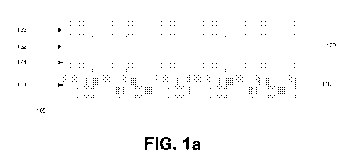
For purposes of illustration, FIG. la includes an illustration of a radome
structure 100
according to embodiments described herein. As shown in FIG. la, a radome
structure 100
may include an inner tuning layer component 110 and a laminate component 120
overlying
the inner tuning layer component 110. According to particular embodiments, and
as further
.. shown in FIG. la, the inner tuning layer component 110 may include a first
inner tuning layer
111. According to still other embodiments, and as also shown in FIG. la, the
laminate
component 120 may include a first fiber reinforced dielectric layer 121, a
second fiber
reinforced dielectric layer 122 overlying the first fiber reinforced
dielectric layer 121, and a
third fiber reinforced dielectric layer 123 overlying the second fiber
reinforced dielectric
layer 122. According to certain embodiments, the first fiber reinforced
dielectric layer 121
may include a first low dielectric constant material. According to still other
embodiments,
the second fiber reinforced dielectric layer 122 may include a first high
dielectric constant
material. According to yet other embodiments, the third fiber reinforced
dielectric layer 123
may include a second low dielectric constant material.
- 3 -
CA 03125118 2021-06-25
WO 2020/139569
PCT/US2019/065947
According to particular embodiments, the inner tuning layer component 110 may
include a thermoset foam or a thermoplastic foam.
According to certain embodiments, where the inner tuning layer component 110
includes a thermoset foam, the thermoset foam may have a particular density.
For example,
the thermoset foam of the inner tuning layer component 110 may have a density
of at least
about 300 kg/m3, such as, at least about 310 kg/m3 or at least about 320 kg/m3
or at least
about 330 kg/m3 or at least about 340 kg/m3 or at least about 350 kg/m3 or at
least about 360
kg/m3 or at least about 370 kg/m3 or at least about 380 kg/m3 or at least
about 390 kg/m3 or at
least about 400 kg/m3 or at least about 410 kg/m3 or at least about 420 kg/m3
or at least about
430 kg/m3 or at least about 440 kg/m3 or at least about 450 kg/m3 or at least
about 460 kg/m3
or at least about 470 kg/m3 or at least about 480 kg/m3 or at least about 490
kg/m3 or even at
least about 500 kg/m3. According to still other embodiments, the thermoset
foam of the inner
tuning layer component 110 may have a density of not greater than about 1000
kg/m3, such
as, not greater than about 990 kg/m3 or not greater than about 980 kg/m3 or
not greater than
about 970 kg/m3 or not greater than about 960 kg/m3 or not greater than about
950 kg/m3 or
not greater than about 940 kg/m3 or not greater than about 930 kg/m3 or not
greater than
about 920 kg/m3 or not greater than about 910 kg/m3 or not greater than about
900 kg/m3 or
not greater than about 890 kg/m3 or not greater than about 880 kg/m3 or not
greater than
about 870 kg/m3 or not greater than about 860 kg/m3 or not greater than about
850 kg/m3 or
not greater than about 840 kg/m3 or not greater than about 830 kg/m3 or not
greater than
about 820 kg/m3 or not greater than about 810 kg/m3 or even not greater than
about 800
kg/m3. It will be appreciated that the density of the thermoset foam of the
inner tuning layer
component 110 may be within a range between any of the minimum and maximum
values
noted above. It will be further appreciated that the density of the thermoset
foam of the inner
tuning layer component 110 may be any value between any of the minimum and
maximum
values noted above.
According to yet other embodiments, where the inner tuning layer component 110
includes a thermoset foam, the thermoset foam may have a particular dielectric
constant. For
example, the thermoset foam of the inner tuning layer component 110 may have a
dielectric
constant of at least about 1.00, such as, at least about 1.05 or at least
about 1.10 or at least
about 1.15 or at least about 1.20 or at least about 1.25 or at least about
1.30 or at least about
1.35 or at least about 1.40 or at least about 1.45 or at least about 1.50 or
at least about 1.55 or
at least about 1.6 or at least about 1.65 or at least about 1.7 or at least
about 1.75 or at least
about 1.8 or at least about 1.85 or at least about 1.9 or at least about 1.95
or at least about 2.0
- 4 -
CA 03125118 2021-06-25
WO 2020/139569
PCT/US2019/065947
or at least about 2.05 or at least about 2.1 or at least about 2.15 or even at
least about 2.2.
According to yet other embodiments, the thermoset foam of the inner tuning
layer component
110 may have a dielectric constant of not greater than about 3.0 or not
greater than about 2.95
or not greater than about 2.9 or not greater than about 2.85 or not greater
than about 2.80 or
not greater than about 2.75 or not greater than about 2.7 or not greater than
about 2.65 or not
greater than about 2.6 or not greater than about 2.55 or even not greater than
about 2.5. It
will be appreciated that the dielectric constant of the thermoset foam of the
inner tuning layer
component 110 may be within a range between any of the minimum and maximum
values
noted above. It will be further appreciated that the dielectric constant of
the thermoset foam
of the inner tuning layer component 110 may be any value between any of the
minimum and
maximum values noted above.
According to certain embodiments, where the inner tuning layer component 110
includes a thermoplastic foam, the thermoplastic foam may have a particular
density. For
example, the thermoplastic foam of the inner tuning layer component 110 may
have a density
of not greater than about 300 kg/m3, such as, not greater than about 295 kg/m3
or not greater
than about 290 kg/m3 or not greater than about 285 kg/m3 or not greater than
about 280 kg/m3
or not greater than about 275 kg/m3 or not greater than about 270 kg/m3 or not
greater than
about 265 kg/m3 or not greater than about 260 kg/m3 or not greater than about
255 kg/m3 or
not greater than about 250 kg/m3 or not greater than about 245 kg/m3 or not
greater than
about 240 kg/m3 or not greater than about 235 kg/m3 or not greater than about
230 kg/m3 or
not greater than about 225 kg/m3 or not greater than about 220 kg/m3 or not
greater than
about 215 kg/m3 or not greater than about 210 kg/m3 or not greater than about
205 kg/m3 or
not greater than about 200 kg/m3. According to still other embodiments, the
thermoplastic
foam of the inner tuning layer component 110 may have a density of at least
about 1 kg/m3,
such as, at least about 10 kg/m3 or at least about 15 kg/m3 or at least about
20 kg/m3 or at
least about 25 kg/m3 or at least about 30 kg/m3 or at least about 35 kg/m3 or
at least about 40
kg/m3 or at least about 45 kg/m3 or at least about 50 kg/m3. It will be
appreciated that the
density of the thermoplastic foam of the inner tuning layer component 110 may
be within a
range between any of the minimum and maximum values noted above. It will be
further
appreciated that the density of the thermoplastic foam of the inner tuning
layer component
110 may be any value between any of the minimum and maximum values noted
above.
According to yet other embodiments, where the inner tuning layer component 110
includes a thermoplastic foam, the thermoplastic foam may have a particular
dielectric
constant. For example, the thermoplastic foam of the inner tuning layer
component 110 may
- 5 -
CA 03125118 2021-06-25
WO 2020/139569
PCT/US2019/065947
have a dielectric constant of not greater than about 1.5 or not greater than
about 1.45 or not
greater than about 1.4 or not greater than about 1.35 or not greater than
about 1.30 or not
greater than about 1.25 or not greater than about 1.20 or not greater than
about 1.15 or not
greater than about 1.10 or not greater than about 1.05 or even not greater
than about 1.00.
According to still other embodiments, the thermoplastic foam of the inner
tuning layer
component 110 may have a dielectric constant of at least about 0.01, such as,
at least about
0.05 or at least about 0.10 or at least about 0.15 or at least about 0.20 or
at least about 1.75 or
at least about 1.8 or at least about 1.85 or at least about 1.9 or at least
about 1.95 or at least
about 2.0 or at least about 2.05 or at least about 2.1 or at least about 2.15
or even at least
about 2.2. It will be appreciated that the dielectric constant of the
thermoplastic foam of the
inner tuning layer component 110 may be within a range between any of the
minimum and
maximum values noted above. It will be further appreciated that the dielectric
constant of the
thermoplastic foam of the inner tuning layer component 110 may be any value
between any
of the minimum and maximum values noted above.
According to still other embodiments, the inner tuning layer component 110 may
include syntactic foam. According to still other embodiments, the inner tuning
layer
component 110 may include a plastic closed cell foam. According to still other
embodiments, the inner tuning layer component 110 may include a combination of
a syntactic
foam, and a plastic closed cell foam. According to still other embodiments,
the inner tuning
layer component 110 may include a syntactic foam, a plastic closed cell foam,
a
polymethacrylimide (PMI), a polycarbonate (PC), a polyetherimide (PEI), a
polyvinyl
chloride (PVC), acrylonitrile butadiene styrene (ABS), styrofoam, or
combinations thereof.
According to yet other embodiments, the inner tuning layer component 110 may
have
a particular thickness. For example, the inner tuning layer component 110 may
have a
thickness of at least about 0.1 mm, such as, at least about 0.5 mm or at least
about 1.0 mm or
at least about 1.5 mm or at least about 2.0 mm or at least about 2.5 mm or at
least about 3.0
mm or at least about 3.5 mm or at least about 4.0 mm or at least about 4.5 mm
or at least
about 5.0 mm. According to yet other embodiments, the inner tuning layer 100
may have a
thickness of not greater than about 12.5 mm, such as, not greater than about
12.0 mm or not
greater than about 11.5 mm or not greater than about 11.0 mm or not greater
than about 10.5
mm or not greater than about 10.0 mm or not greater than about 9.5 mm or not
greater than
about 9.0 mm or not greater than about 8.5 mm or not greater than about 8.0 mm
or not
greater than about 7.5 mm or not greater than about 7.0 mm or not greater than
about 6.5 or
even not greater than about 6.0 mm. It will be appreciated that the thickness
of the inner
- 6 -
CA 03125118 2021-06-25
WO 2020/139569
PCT/US2019/065947
tuning layer component 110 may be within a range between any of the minimum
and
maximum values noted above. It will be further appreciated that the thickness
of the inner
tuning layer component 110 may be any value between any of the minimum and
maximum
values noted above.
According to particular embodiments, the inner tuning layer component 110 may
be a
single layer of material. According to yet other embodiments and as shown in
FIG. la, the
single layer of material may be a single first inner tuning layer 111.
According to particular embodiments, the first inner tuning layer 111 may
include a
thermoset foam or a thermoplastic foam.
According to certain embodiments, where the first inner tuning layer 111
includes a
thermoset foam, the thermoset foam may have a particular density. For example,
the
thermoset foam of the first inner tuning layer 111 may have a density of at
least about 300
kg/m3, such as, at least about 310 kg/m3 or at least about 320 kg/m3 or at
least about 330
kg/m3 or at least about 340 kg/m3 or at least about 350 kg/m3 or at least
about 360 kg/m3 or at
least about 370 kg/m3 or at least about 380 kg/m3 or at least about 390 kg/m3
or at least about
400 kg/m3 or at least about 410 kg/m3 or at least about 420 kg/m3 or at least
about 430 kg/m3
or at least about 440 kg/m3 or at least about 450 kg/m3 or at least about 460
kg/m3 or at least
about 470 kg/m3 or at least about 480 kg/m3 or at least about 490 kg/m3 or
even at least about
500 kg/m3. According to still other embodiments, the thermoset foam of the
first inner tuning
layer 111 may have a density of not greater than about 1000 kg/m3, such as,
not greater than
about 990 kg/m3 or not greater than about 980 kg/m3 or not greater than about
970 kg/m3 or
not greater than about 960 kg/m3 or not greater than about 950 kg/m3 or not
greater than
about 940 kg/m3 or not greater than about 930 kg/m3 or not greater than about
920 kg/m3 or
not greater than about 910 kg/m3 or not greater than about 900 kg/m3 or not
greater than
about 890 kg/m3 or not greater than about 880 kg/m3 or not greater than about
870 kg/m3 or
not greater than about 860 kg/m3 or not greater than about 850 kg/m3 or not
greater than
about 840 kg/m3 or not greater than about 830 kg/m3 or not greater than about
820 kg/m3 or
not greater than about 810 kg/m3 or even not greater than about 800 kg/m3. It
will be
appreciated that the density of the thermoset foam of the first inner tuning
layer 111 may be
within a range between any of the minimum and maximum values noted above. It
will be
further appreciated that the density of the thermoset foam of the first inner
tuning layer 111
may be any value between any of the minimum and maximum values noted above.
According to yet other embodiments, where the first inner tuning layer 111
includes a
thermoset foam, the thermoset foam may have a particular dielectric constant.
For example,
- 7 -
CA 03125118 2021-06-25
WO 2020/139569
PCT/US2019/065947
the thermoset foam of the first inner tuning layer 111 may have a dielectric
constant of at
least about 1.00, such as, at least about 1.05 or at least about 1.10 or at
least about 1.15 or at
least about 1.20 or at least about 1.25 or at least about 1.30 or at least
about 1.35 or at least
about 1.40 or at least about 1.45 or at least about 1.50 or at least about
1.55 or at least about
1.6 or at least about 1.65 or at least about 1.7 or at least about 1.75 or at
least about 1.8 or at
least about 1.85 or at least about 1.9 or at least about 1.95 or at least
about 2.0 or at least
about 2.05 or at least about 2.1 or at least about 2.15 or even at least about
2.2. According to
yet other embodiments, the thermoset foam of the first inner tuning layer 111
may have a
dielectric constant of not greater than about 3.0 or not greater than about
2.95 or not greater
than about 2.9 or not greater than about 2.85 or not greater than about 2.80
or not greater than
about 2.75 or not greater than about 2.7 or not greater than about 2.65 or not
greater than
about 2.6 or not greater than about 2.55 or even not greater than about 2.5.
It will be
appreciated that the dielectric constant of the thermoset foam of the first
inner tuning layer
111 may be within a range between any of the minimum and maximum values noted
above.
It will be further appreciated that the dielectric constant of the thermoset
foam of the first
inner tuning layer 111 may be any value between any of the minimum and maximum
values
noted above.
According to certain embodiments, where the first inner tuning layer 111
includes a
thermoplastic foam, the thermoplastic foam may have a particular density. For
example, the
thermoplastic foam of the first inner tuning layer 111 may have a density of
not greater than
about 300 kg/m3, such as, not greater than about 295 kg/m3 or not greater than
about 290
kg/m3 or not greater than about 285 kg/m3 or not greater than about 280 kg/m3
or not greater
than about 275 kg/m3 or not greater than about 270 kg/m3 or not greater than
about 265 kg/m3
or not greater than about 260 kg/m3 or not greater than about 255 kg/m3 or not
greater than
about 250 kg/m3 or not greater than about 245 kg/m3 or not greater than about
240 kg/m3 or
not greater than about 235 kg/m3 or not greater than about 230 kg/m3 or not
greater than
about 225 kg/m3 or not greater than about 220 kg/m3 or not greater than about
215 kg/m3 or
not greater than about 210 kg/m3 or not greater than about 205 kg/m3 or not
greater than
about 200 kg/m3. According to still other embodiments, the thermoplastic foam
of the first
inner tuning layer 111 may have a density of at least about 1 kg/m3, such as,
at least about 10
kg/m3 or at least about 15 kg/m3 or at least about 20 kg/m3 or at least about
25 kg/m3 or at
least about 30 kg/m3 or at least about 35 kg/m3 or at least about 40 kg/m3 or
at least about 45
kg/m3 or at least about 50 kg/m3. It will be appreciated that the density of
the thermoplastic
foam of the first inner tuning layer 111 may be within a range between any of
the minimum
- 8 -
CA 03125118 2021-06-25
WO 2020/139569
PCT/US2019/065947
and maximum values noted above. It will be further appreciated that the
density of the
thermoplastic foam of the first inner tuning layer 111 may be any value
between any of the
minimum and maximum values noted above.
According to yet other embodiments, where the first inner tuning layer 111
includes a
thermoplastic foam, the thermoplastic foam may have a particular dielectric
constant. For
example, the thermoplastic foam of the first inner tuning layer 111 may have a
dielectric
constant of not greater than about 1.5 or not greater than about 1.45 or not
greater than about
1.4 or not greater than about 1.35 or not greater than about 1.30 or not
greater than about 1.25
or not greater than about 1.20 or not greater than about 1.15 or not greater
than about 1.10 or
not greater than about 1.05 or even not greater than about 1.00. According to
still other
embodiments, the thermoplastic foam of the first inner tuning layer 111 may
have a dielectric
constant of at least about 0.01, such as, at least about 0.05 or at least
about 0.10 or at least
about 0.15 or at least about 0.20 or at least about 1.75 or at least about 1.8
or at least about
1.85 or at least about 1.9 or at least about 1.95 or at least about 2.0 or at
least about 2.05 or at
least about 2.1 or at least about 2.15 or even at least about 2.2. It will be
appreciated that the
dielectric constant of the thermoplastic foam of the first inner tuning layer
111 may be within
a range between any of the minimum and maximum values noted above. It will be
further
appreciated that the dielectric constant of the thermoplastic foam of the
first inner tuning
layer 111 may be any value between any of the minimum and maximum values noted
above.
According to still other embodiments, the first inner tuning layer component
111 may
include syntactic foam. According to still other embodiments, the first inner
tuning layer
component 111 may include a plastic closed cell foam. According to still other
embodiments, the first inner tuning layer component 111 may include a
combination of a
syntactic foam, and a plastic closed cell foam. According to still other
embodiments, the first
inner tuning layer component 111 may include a syntactic foam, a plastic
closed cell foam, a
polymethacrylimide (PMI), a polycarbonate (PC), a polyetherimide (PEI), a
polyvinyl
chloride (PVC), acrylonitrile butadiene styrene (ABS), styrofoam, or
combinations thereof.
According to yet other embodiments, the first inner tuning layer 111 may have
a
particular thickness. For example, the first inner tuning layer 111 may have a
thickness of at
least about 0.1 mm, such as, at least about 0.3 mm or at least about 0.5 mm or
at least about
0.7 mm or at least about 1.0 mm or at least about 1.3 mm or at least about 1.5
mm or at least
about 1.7 mm or at least about 2.0 mm or at least about 2.5 mm or at least
about 3.0 mm.
According to yet other embodiments, the inner tuning layer 100 may have a
thickness of not
greater than about 6.25 mm, such as, not greater than about 6.0 mm or not
greater than about
- 9 -
CA 03125118 2021-06-25
WO 2020/139569
PCT/US2019/065947
5.75 mm or not greater than about 5.5 mm or not greater than about 5.25 mm or
not greater
than about 5.0 mm or not greater than about 4.75 mm or not greater than about
4.5 mm or not
greater than about 4.25 mm or not greater than about 4.0 mm or not greater
than about 3.75
mm or even not greater than about 3.5 mm. It will be appreciated that the
thickness of the
first inner tuning layer 111 may be within a range between any of the minimum
and
maximum values noted above. It will be further appreciated that the thickness
of the first
inner tuning layer 111 may be any value between any of the minimum and maximum
values
noted above.
According to yet other embodiments, the first low dielectric constant material
of the
.. first fiber reinforced dielectric layer 121 may have a particular
dielectric constant. For
example, the first low dielectric constant material may have a dielectric
constant of not
greater than about 3.5, such as not greater than about 3.45 or not greater
than about 3.4 or not
greater than about 3.35 or not greater than about 3.3 or not greater than
about 3.25 or not
greater than about 3.2 or not greater than about 3.15 or not greater than
about 3.1 or not
greater than about 3.05 or even not greater than about 3Ø According to still
other
embodiments, the first low dielectric constant material may have a dielectric
constant of at
least about 1.5, such as at least about 1.55 or at least about 1.6 or at least
about 1.65 or at least
about 1.7 or at least about 1.75 or at least about 1.8 or at least about 1.85
or at least about 1.9
or at least about 1.95 or even at least about 2Ø It will be appreciated that
the dielectric
constant of the first low dielectric constant material may be within a range
between any of the
minimum and maximum values noted above. It will be further appreciated that
the dielectric
constant of the first low dielectric constant material may be any value
between any of the
minimum and maximum values noted above.
According to yet other embodiments, the first fiber reinforced dielectric
layer 121
may have a particular dielectric constant. For example, the first fiber
reinforced dielectric
layer 121 may have a dielectric constant of not greater than about 3.5, such
as not greater
than about 3.45 or not greater than about 3.4 or not greater than about 3.35
or not greater than
about 3.3 or not greater than about 3.25 or not greater than about 3.2 or not
greater than about
3.15 or not greater than about 3.1 or not greater than about 3.05 or even not
greater than
about 3Ø According to still other embodiments, the first fiber reinforced
dielectric layer 121
may have a dielectric constant of at least about 1.5, such as at least about
1.55 or at least
about 1.6 or at least about 1.65 or at least about 1.7 or at least about 1.75
or at least about 1.8
or at least about 1.85 or at least about 1.9 or at least about 1.95 or even at
least about 2Ø It
will be appreciated that the dielectric constant of the first fiber reinforced
dielectric layer 121
- 10 -
CA 03125118 2021-06-25
WO 2020/139569
PCT/US2019/065947
may be within a range between any of the minimum and maximum values noted
above. It
will be further appreciated that the dielectric constant of the first fiber
reinforced dielectric
layer 121 may be any value between any of the minimum and maximum values noted
above.
According to still other embodiments, the first low dielectric constant
material of the
first fiber reinforced dielectric layer 121 may include polyethylene (PE),
polypropylene (PP),
polytetrafluoroethylene (PTFE), polyamide (PA) or combinations thereof.
According to still
other embodiments, the first low dielectric constant material of the first
fiber reinforced
dielectric layer 121 may include polyethylene (PE) fibers, polypropylene (PP)
fibers,
polytetrafluoroethylene (PTFE) fibers, polyamide (PA) fibers, or combinations
thereof.
According to yet other embodiments, the first low dielectric constant material
of the first
fiber reinforced dielectric layer 121 may include polyethylene (PE),
polypropylene (PP),
polytetrafluoroethylene (PTFE), polyamide (PA), polyethylene (PE) fibers,
polypropylene
(PP) fibers, polytetrafluoroethylene (PTFE) fibers, polyamide (PA) fibers, or
combinations
thereof.
According to still other embodiments, the first fiber reinforced dielectric
layer 121
may include polyethylene (PE), polypropylene (PP), polytetrafluoroethylene
(PTFE),
polyamide (PA) or combinations thereof. According to still other embodiments,
the first
fiber reinforced dielectric layer 121 may include polyethylene (PE) fibers,
polypropylene
(PP) fibers, polytetrafluoroethylene (PTFE) fibers, polyamide (PA) fibers, or
combinations
thereof. According to yet other embodiments, the first fiber reinforced
dielectric layer 121
may include polyethylene (PE), polypropylene (PP), polytetrafluoroethylene
(PTFE),
polyamide (PA), polyethylene (PE) fibers, polypropylene (PP) fibers,
polytetrafluoroethylene
(PTFE) fibers, polyamide (PA) fibers, or combinations thereof.
According to yet other embodiments, the first fiber reinforced dielectric
layer 121
may have a particular thickness. For example, the first fiber reinforced
dielectric layer 121
may have a thickness of at least about 0.10 mm, such as at least about 0.11 mm
or at least
about 0.12 mm or at least about 0.13 mm or at least about 0.14 mm or at least
about 0.15 mm
or at least about 0.2 mm or at least about 0.3 mm or at least about 0.4 mm or
at least about 0.5
mm or at least about 1.0 mm or at least about 1.5 mm or even at least about
2.0mm.
According to still other embodiments, the first fiber reinforced dielectric
layer 121 may have
a thickness of not greater than about 6.5 mm, such as not greater than about
6.0 mm or not
greater than about 5.5 mm or not greater than about 5.0 mm or not greater than
about 4.5 or
even not greater than about 4.0 mm. It will be appreciated that the thickness
of the first fiber
reinforced dielectric layer 121 may be within a range between any of the
minimum and
- 11-
CA 03125118 2021-06-25
WO 2020/139569
PCT/US2019/065947
maximum values noted above. It will be further appreciated that the thickness
of the first
fiber reinforced dielectric layer 121 may be any value between any of the
minimum and
maximum values noted above.
According to yet other embodiments, the first high dielectric constant
material of the
second fiber reinforced dielectric layer 122 may have a particular dielectric
constant. For
example, the first high dielectric constant material may have a dielectric
constant of not
greater than about 8, such as not greater than about 8.75 or not greater than
about 8.5 or not
greater than about 8.25 or not greater than about 8.0 or not greater than
about 7.75 or not
greater than about 7.5 or not greater than about 7.25 or not greater than
about 7.0 or not
greater than about 6.75 or not greater than about 6.5 or not greater than
about 6.25 or not
greater than about 6.0 or not greater than about 5.75 or not greater than
about 5.5 or not
greater than about 5.25 or not greater than about 5Ø According to still
other embodiments,
the first high dielectric constant material may have a dielectric constant of
at least about 2.5,
such as at least about 2.75 or at least about 3.0 or at least about 3.25 or at
least about 3.5 or at
least about 3.75 or at least about 4.0 or at least about 4.25 or at least
about 4.5 or even at least
about 4.75. It will be appreciated that the dielectric constant of the first
high dielectric
constant material may be within a range between any of the minimum and maximum
values
noted above. It will be further appreciated that the dielectric constant of
the first high
dielectric constant material may be any value between any of the minimum and
maximum
values noted above.
According to yet other embodiments, the second fiber reinforced dielectric
layer 122
may have a particular dielectric constant. For example, the second fiber
reinforced dielectric
layer 122 may have a dielectric constant of not greater than about 8, such as
not greater than
about 8.75 or not greater than about 8.5 or not greater than about 8.25 or not
greater than
about 8.0 or not greater than about 7.75 or not greater than about 7.5 or not
greater than about
7.25 or not greater than about 7.0 or not greater than about 6.75 or not
greater than about 6.5
or not greater than about 6.25 or not greater than about 6.0 or not greater
than about 5.75 or
not greater than about 5.5 or not greater than about 5.25 or not greater than
about 5Ø
According to still other embodiments, the second fiber reinforced dielectric
layer 122 may
have a dielectric constant of at least about 2.5, such as at least about 2.75
or at least about 3.0
or at least about 3.25 or at least about 3.5 or at least about 3.75 or at
least about 4.0 or at least
about 4.25 or at least about 4.5 or even at least about 4.75. It will be
appreciated that the
second fiber reinforced dielectric layer 122 may be within a range between any
of the
minimum and maximum values noted above. It will be further appreciated that
the second
- 12-
CA 03125118 2021-06-25
WO 2020/139569
PCT/US2019/065947
fiber reinforced dielectric layer 122 may be any value between any of the
minimum and
maximum values noted above.
According to still other embodiments, the first high dielectric constant
material of the
second fiber reinforced dielectric layer 122 may include glass fibers in a
polymer matrix.
According to still other embodiments, the first high dielectric constant
material of the second
fiber reinforced dielectric layer 122 may include glass fibers in a polyester
matrix.
According to yet other embodiments, the first high dielectric constant
material of the second
fiber reinforced dielectric layer 122 may include glass fibers in a resin
matrix. According to
still other embodiments, the first high dielectric constant material of the
second fiber
reinforced dielectric layer 122 may include glass fibers in a cyanate ester
matrix. According
to still other embodiments, the first high dielectric constant material of the
second fiber
reinforced dielectric layer 122 may include any combination of glass fibers in
a polymer
matrix, glass fibers in a polyester matrix, glass fibers in a resin matrix,
and glass fibers in a
cyanate ester matrix.
According to still other embodiments, the second fiber reinforced dielectric
layer 122
may include glass fibers in a polymer matrix. According to still other
embodiments, the
second fiber reinforced dielectric layer 122 may include glass fibers in a
polyester matrix.
According to yet other embodiments, the second fiber reinforced dielectric
layer 122 may
include glass fibers in a resin matrix. According to still other embodiments,
the second fiber
reinforced dielectric layer 122 may include glass fibers in a cyanate ester
matrix. According
to still other embodiments, the second fiber reinforced dielectric layer 122
may include any
combination of glass fibers in a polymer matrix, glass fibers in a polyester
matrix, glass fibers
in a resin matrix, and glass fibers in a cyanate ester matrix.
According to yet other embodiments, the second fiber reinforced dielectric
layer 122
may have a particular thickness. For example, the second fiber reinforced
dielectric layer 122
may have a thickness of at least about 0.10 mm, such as at least about 0.11 mm
or at least
about 0.12 mm or at least about 0.13 mm or at least about 0.14 mm or at least
about 0.15 mm
or at least about 0.2 mm or at least about 0.3 mm or at least about 0.4 mm or
at least about 0.5
mm or at least about 1.0 mm or at least about 1.5 mm or even at least about
2.0mm.
According to still other embodiments, the second fiber reinforced dielectric
layer 122 may
have a thickness of not greater than about 6.5 mm, such as not greater than
about 6.0 mm or
not greater than about 5.5 mm or not greater than about 5.0 mm or not greater
than about 4.5
or even not greater than about 4.0 mm. It will be appreciated that the
thickness of the second
fiber reinforced dielectric layer 122 may be within a range between any of the
minimum and
- 13 -
CA 03125118 2021-06-25
WO 2020/139569
PCT/US2019/065947
maximum values noted above. It will be further appreciated that the thickness
of the second
fiber reinforced dielectric layer 122 may be any value between any of the
minimum and
maximum values noted above.
According to yet other embodiments, the second low dielectric constant
material of
the third fiber reinforced dielectric layer 123 may have a particular
dielectric constant. For
example, the second low dielectric constant material may have a dielectric
constant of not
greater than about 3.5, such as not greater than about 3.45 or not greater
than about 3.4 or not
greater than about 3.35 or not greater than about 3.3 or not greater than
about 3.25 or not
greater than about 3.2 or not greater than about 3.15 or not greater than
about 3.1 or not
greater than about 3.05 or even not greater than about 3Ø According to still
other
embodiments, the second low dielectric constant material may have a dielectric
constant of at
least about 1.5, such as at least about 1.55 or at least about 1.6 or at least
about 1.65 or at least
about 1.7 or at least about 1.75 or at least about 1.8 or at least about 1.85
or at least about 1.9
or at least about 1.95 or even at least about 2Ø It will be appreciated that
the dielectric
constant of the second low dielectric constant material may be within a range
between any of
the minimum and maximum values noted above. It will be further appreciated
that the
dielectric constant of the second low dielectric constant material may be any
value between
any of the minimum and maximum values noted above.
According to yet other embodiments, the third fiber reinforced dielectric
layer 123
may have a particular dielectric constant. For example, the third fiber
reinforced dielectric
layer 123 may have a dielectric constant of not greater than about 3.5, such
as not greater
than about 3.45 or not greater than about 3.4 or not greater than about 3.35
or not greater than
about 3.3 or not greater than about 3.25 or not greater than about 3.2 or not
greater than about
3.15 or not greater than about 3.1 or not greater than about 3.05 or even not
greater than
about 3Ø According to still other embodiments, the third fiber reinforced
dielectric layer
123 may have a dielectric constant of at least about 1.5, such as at least
about 1.55 or at least
about 1.6 or at least about 1.65 or at least about 1.7 or at least about 1.75
or at least about 1.8
or at least about 1.85 or at least about 1.9 or at least about 1.95 or even at
least about 2Ø It
will be appreciated that the dielectric constant of the third fiber reinforced
dielectric layer 123
may be within a range between any of the minimum and maximum values noted
above. It
will be further appreciated that the dielectric constant of the third fiber
reinforced dielectric
layer 123 may be any value between any of the minimum and maximum values noted
above.
According to still other embodiments, the second low dielectric constant
material of
the third fiber reinforced dielectric layer 123 may include polyethylene (PE),
polypropylene
- 14 -
CA 03125118 2021-06-25
WO 2020/139569
PCT/US2019/065947
(PP), polytetrafluoroethylene (PTFE), polyamide (PA) or combinations thereof.
According
to still other embodiments, the second low dielectric constant material of the
third fiber
reinforced dielectric layer 123 may include polyethylene (PE) fibers,
polypropylene (PP)
fibers, polytetrafluoroethylene (PTFE) fibers, polyamide (PA) fibers, or
combinations
thereof. According to yet other embodiments, the second low dielectric
constant material of
the third fiber reinforced dielectric layer 123 may include polyethylene (PE),
polypropylene
(PP), polytetrafluoroethylene (PTFE), polyamide (PA), polyethylene (PE)
fibers,
polypropylene (PP) fibers, polytetrafluoroethylene (PTFE) fibers, polyamide
(PA) fibers, or
combinations thereof.
According to still other embodiments, the third fiber reinforced dielectric
layer 123
may include polyethylene (PE), polypropylene (PP), polytetrafluoroethylene
(PTFE),
polyamide (PA) or combinations thereof. According to still other embodiments,
the third
fiber reinforced dielectric layer 123 may include polyethylene (PE) fibers,
polypropylene
(PP) fibers, polytetrafluoroethylene (PTFE) fibers, polyamide (PA) fibers, or
combinations
thereof. According to yet other embodiments, the third fiber reinforced
dielectric layer 123
may include polyethylene (PE), polypropylene (PP), polytetrafluoroethylene
(PTFE),
polyamide (PA), polyethylene (PE) fibers, polypropylene (PP) fibers,
polytetrafluoroethylene
(PTFE) fibers, polyamide (PA) fibers, or combinations thereof.
According to yet other embodiments, the third fiber reinforced dielectric
layer 123
may have a particular thickness. For example, the third fiber reinforced
dielectric layer 123
may have a thickness of at least about 0.10 mm, such as at least about 0.11 mm
or at least
about 0.12 mm or at least about 0.13 mm or at least about 0.14 mm or at least
about 0.15 mm
or at least about 0.2 mm or at least about 0.3 mm or at least about 0.4 mm or
at least about 0.5
mm or at least about 1.0 mm or at least about 1.5 mm or even at least about
2.0mm.
According to still other embodiments, the third fiber reinforced dielectric
layer 123 may have
a thickness of not greater than about 6.5 mm, such as not greater than about
6.0 mm or not
greater than about 5.5 mm or not greater than about 5.0 mm or not greater than
about 4.5 or
even not greater than about 4.0 mm. It will be appreciated that the thickness
of the third fiber
reinforced dielectric layer 123 may be within a range between any of the
minimum and
maximum values noted above. It will be further appreciated that the thickness
of the third
fiber reinforced dielectric layer 123 may be any value between any of the
minimum and
maximum values noted above.
FIG. lb includes an illustration of an alternative embodiment of a radome
structure.
For purposes of illustration and as shown in FIG. lb, a radome structure 101
may include an
- 15 -
CA 03125118 2021-06-25
WO 2020/139569
PCT/US2019/065947
inner tuning layer component 110 and a laminate component 120 overlying the
inner tuning
layer component 110. According to particular embodiments, and as further shown
in FIG.
lb, the inner tuning layer component 110 may include a first inner tuning
layer 111 and a
second inner tuning layer 112. According to still other embodiments, and as
also shown in
FIG. la, the laminate component 120 may include a first fiber reinforced
dielectric layer 121,
a second fiber reinforced dielectric layer 122 overlying the first fiber
reinforced dielectric
layer 121, and a third fiber reinforced dielectric layer 123 overlying the
second fiber
reinforced dielectric layer 122. According to certain embodiments, the first
fiber reinforced
dielectric layer 121 may include a first low dielectric constant material.
According to still
other embodiments, the second fiber reinforced dielectric layer 122 may
include a first high
dielectric constant material. According to yet other embodiments, the third
fiber reinforced
dielectric layer 123 may include a second low dielectric constant material.
It will be appreciated that the radome structure 101 and all components
described in
reference to the radome structure 101 as shown in FIG. lb may have any of the
characteristics described herein with reference to corresponding components in
FIG. la. In
particular, the characteristics of the radome structure 101, the inner tuning
layer component
110, the laminate component 120, the first inner tuning layer 111, the first
fiber reinforced
dielectric layer 121, the second fiber reinforced dielectric layer 122, and
the third fiber
reinforced dielectric layer 123 shown in FIG. lb may have any of the
corresponding
characteristics described herein in reference to the radome structure 100, the
inner tuning
layer component 110, the laminate component 120, the first inner tuning layer
111, the first
fiber reinforced dielectric layer 121, the second fiber reinforced dielectric
layer 122, and the
third fiber reinforced dielectric layer 123 shown in FIG. la, respectively.
Referring now specifically to FIG. lb, according to certain embodiments and as
shown in FIG. lb, the second inner tuning layer 112 of the of the inner tuning
layer
component 110 may located between the first inner tuning layer 111 and the
laminate
component 120.
According to still other embodiments, the dielectric constant of the first
inner tuning
layer 111 may be less than a dielectric constant of the second inner tuning
layer 112.
According to particular embodiments, the second inner tuning layer 112 may
include
a thermoset foam or a thermoplastic foam.
According to certain embodiments, where the second inner tuning layer 112
includes
a thermoset foam, the thermoset foam may have a particular density. For
example, the
thermoset foam of the second inner tuning layer 112 may have a density of at
least about 300
- 16-
CA 03125118 2021-06-25
WO 2020/139569
PCT/US2019/065947
kg/m3, such as, at least about 310 kg/m3 or at least about 320 kg/m3 or at
least about 330
kg/m3 or at least about 340 kg/m3 or at least about 350 kg/m3 or at least
about 360 kg/m3 or at
least about 370 kg/m3 or at least about 380 kg/m3 or at least about 390 kg/m3
or at least about
400 kg/m3 or at least about 410 kg/m3 or at least about 420 kg/m3 or at least
about 430 kg/m3
or at least about 440 kg/m3 or at least about 450 kg/m3 or at least about 460
kg/m3 or at least
about 470 kg/m3 or at least about 480 kg/m3 or at least about 490 kg/m3 or
even at least about
500 kg/m3. According to still other embodiments, the thermoset foam of the
second inner
tuning layer 112 may have a density of not greater than about 1000 kg/m3, such
as, not
greater than about 990 kg/m3 or not greater than about 980 kg/m3 or not
greater than about
.. 970 kg/m3 or not greater than about 960 kg/m3 or not greater than about 950
kg/m3 or not
greater than about 940 kg/m3 or not greater than about 930 kg/m3 or not
greater than about
920 kg/m3 or not greater than about 910 kg/m3 or not greater than about 900
kg/m3 or not
greater than about 890 kg/m3 or not greater than about 880 kg/m3 or not
greater than about
870 kg/m3 or not greater than about 860 kg/m3 or not greater than about 850
kg/m3 or not
greater than about 840 kg/m3 or not greater than about 830 kg/m3 or not
greater than about
820 kg/m3 or not greater than about 810 kg/m3 or even not greater than about
800 kg/m3. It
will be appreciated that the density of the thermoset foam of the second inner
tuning layer
112 may be within a range between any of the minimum and maximum values noted
above.
It will be further appreciated that the density of the thermoset foam of the
second inner tuning
layer 112 may be any value between any of the minimum and maximum values noted
above.
According to yet other embodiments, where the second inner tuning layer 112
includes a thermoset foam, the thermoset foam may have a particular dielectric
constant. For
example, the thermoset foam of the second inner tuning layer 112 may have a
dielectric
constant of at least about 1.00, such as, at least about 1.05 or at least
about 1.10 or at least
about 1.15 or at least about 1.20 or at least about 1.25 or at least about
1.30 or at least about
1.35 or at least about 1.40 or at least about 1.45 or at least about 1.50 or
at least about 1.55 or
at least about 1.6 or at least about 1.65 or at least about 1.7 or at least
about 1.75 or at least
about 1.8 or at least about 1.85 or at least about 1.9 or at least about 1.95
or at least about 2.0
or at least about 2.05 or at least about 2.1 or at least about 2.15 or even at
least about 2.2.
According to yet other embodiments, the thermoset foam of the second inner
tuning layer 112
may have a dielectric constant of not greater than about 3.0 or not greater
than about 2.95 or
not greater than about 2.9 or not greater than about 2.85 or not greater than
about 2.80 or not
greater than about 2.75 or not greater than about 2.7 or not greater than
about 2.65 or not
greater than about 2.6 or not greater than about 2.55 or even not greater than
about 2.5. It
- 17 -
CA 03125118 2021-06-25
WO 2020/139569
PCT/US2019/065947
will be appreciated that the dielectric constant of the thermoset foam of the
second inner
tuning layer 112 may be within a range between any of the minimum and maximum
values
noted above. It will be further appreciated that the dielectric constant of
the thermoset foam
of the second inner tuning layer 112 may be any value between any of the
minimum and
maximum values noted above.
According to certain embodiments, where the second inner tuning layer 112
includes
a thermoplastic foam, the thermoplastic foam may have a particular density.
For example,
the thermoplastic foam of the second inner tuning layer 112 may have a density
of not greater
than about 300 kg/m3, such as, not greater than about 295 kg/m3 or not greater
than about 290
kg/m3 or not greater than about 285 kg/m3 or not greater than about 280 kg/m3
or not greater
than about 275 kg/m3 or not greater than about 270 kg/m3 or not greater than
about 265 kg/m3
or not greater than about 260 kg/m3 or not greater than about 255 kg/m3 or not
greater than
about 250 kg/m3 or not greater than about 245 kg/m3 or not greater than about
240 kg/m3 or
not greater than about 235 kg/m3 or not greater than about 230 kg/m3 or not
greater than
about 225 kg/m3 or not greater than about 220 kg/m3 or not greater than about
215 kg/m3 or
not greater than about 210 kg/m3 or not greater than about 205 kg/m3 or not
greater than
about 200 kg/m3. According to still other embodiments, the thermoplastic foam
of the second
inner tuning layer 112 may have a density of at least about 1 kg/m3, such as,
at least about 10
kg/m3 or at least about 15 kg/m3 or at least about 20 kg/m3 or at least about
25 kg/m3 or at
least about 30 kg/m3 or at least about 35 kg/m3 or at least about 40 kg/m3 or
at least about 45
kg/m3 or at least about 50 kg/m3. It will be appreciated that the density of
the thermoplastic
foam of the second inner tuning layer 112 may be within a range between any of
the
minimum and maximum values noted above. It will be further appreciated that
the density of
the thermoplastic foam of the second inner tuning layer 112 may be any value
between any of
the minimum and maximum values noted above.
According to yet other embodiments, where the second inner tuning layer 112
includes a thermoplastic foam, the thermoplastic foam may have a particular
dielectric
constant. For example, the thermoplastic foam of the second inner tuning layer
112 may
have a dielectric constant of not greater than about 1.5 or not greater than
about 1.45 or not
.. greater than about 1.4 or not greater than about 1.35 or not greater than
about 1.30 or not
greater than about 1.25 or not greater than about 1.20 or not greater than
about 1.15 or not
greater than about 1.10 or not greater than about 1.05 or even not greater
than about 1.00.
According to still other embodiments, the thermoplastic foam of the second
inner tuning layer
112 may have a dielectric constant of at least about 0.01, such as, at least
about 0.05 or at
- 18 -
CA 03125118 2021-06-25
WO 2020/139569
PCT/US2019/065947
least about 0.10 or at least about 0.15 or at least about 0.20 or at least
about 1.75 or at least
about 1.8 or at least about 1.85 or at least about 1.9 or at least about 1.95
or at least about 2.0
or at least about 2.05 or at least about 2.1 or at least about 2.15 or even at
least about 2.2. It
will be appreciated that the dielectric constant of the thermoplastic foam of
the second inner
tuning layer 112 may be within a range between any of the minimum and maximum
values
noted above. It will be further appreciated that the dielectric constant of
the thermoplastic
foam of the second inner tuning layer 112 may be any value between any of the
minimum
and maximum values noted above.
According to still other embodiments, the second inner tuning layer component
112
may include syntactic foam. According to still other embodiments, the second
inner tuning
layer component 112 may include a plastic closed cell foam. According to still
other
embodiments, the second inner tuning layer component 112 may include a
combination of a
syntactic foam, and a plastic closed cell foam. According to still other
embodiments, the
second inner tuning layer component 112 may include a syntactic foam, a
plastic closed cell
foam, a polymethacrylimide (PMI), a polycarbonate (PC), a polyetherimide
(PEI), a
polyvinyl chloride (PVC), acrylonitrile butadiene styrene (ABS), styrofoam, or
combinations
thereof.
According to yet other embodiments, the second inner tuning layer 112 may have
a
particular thickness. For example, the second inner tuning layer 112 may have
a thickness of
at least about 0.1 mm, such as, at least about 0.3 mm or at least about 0.5 mm
or at least about
0.7 mm or at least about 1.0 mm or at least about 1.3 mm or at least about 1.5
mm or at least
about 1.7 mm or at least about 2.0 mm or at least about 2.5 mm or at least
about 3.0 mm.
According to yet other embodiments, the inner tuning layer 100 may have a
thickness of not
greater than about 6.25 mm, such as, not greater than about 6.0 mm or not
greater than about
5.75 mm or not greater than about 5.5 mm or not greater than about 5.25 mm or
not greater
than about 5.0 mm or not greater than about 4.75 mm or not greater than about
4.5 mm or not
greater than about 4.25 mm or not greater than about 4.0 mm or not greater
than about 3.75
mm or even not greater than about 3.5 mm. It will be appreciated that the
thickness of the
second inner tuning layer 112 may be within a range between any of the minimum
and
maximum values noted above. It will be further appreciated that the thickness
of the second
inner tuning layer 112 may be any value between any of the minimum and maximum
values
noted above.
FIG. 2a includes an illustration of yet another alternative embodiment of a
radome
structure. For purposes of illustration and as shown in FIG. 2a, a radome
structure 200 may
- 19-
CA 03125118 2021-06-25
WO 2020/139569
PCT/US2019/065947
include an inner tuning layer component 210, a laminate component 220
overlying the inner
tuning layer component 210 and a protection layer 230 overlying the laminate
component
220. According to particular embodiments, and as further shown in FIG. 2a, the
inner tuning
layer component 210 may include a first inner tuning layer 211. According to
still other
embodiments, and as also shown in FIG. 2a, the laminate component 220 may
include a first
fiber reinforced dielectric layer 221, a second fiber reinforced dielectric
layer 222 overlying
the first fiber reinforced dielectric layer 221, and a third fiber reinforced
dielectric layer 223
overlying the second fiber reinforced dielectric layer 222. According to
certain
embodiments, the first fiber reinforced dielectric layer 221 may include a
first low dielectric
constant material. According to still other embodiments, the second fiber
reinforced
dielectric layer 222 may include a first high dielectric constant material.
According to yet
other embodiments, the third fiber reinforced dielectric layer 223 may include
a second low
dielectric constant material.
It will be appreciated that the radome structure 200 and all components
described in
reference to the radome structure 200 as shown in FIG. 2a may have any of the
characteristics
described herein with reference to corresponding components in FIGs. la and
lb. In
particular, the characteristics of the radome structure 200, the inner tuning
layer component
210, the laminate component 220, the first inner tuning layer 211, the first
fiber reinforced
dielectric layer 221, the second fiber reinforced dielectric layer 222, and
the third fiber
reinforced dielectric layer 223 shown in FIG. 2a may have any of the
corresponding
characteristics described herein in reference to the radome structure 100
(101), the inner
tuning layer component 110, the laminate component 120, the first inner tuning
layer 111, the
second turning layer 112, the first fiber reinforced dielectric layer 121, the
second fiber
reinforced dielectric layer 122, and the third fiber reinforced dielectric
layer 123 shown in
FIGs. la and lb, respectively.
Referring now specifically to FIG. 2a, according to certain embodiments, the
protective layer may include an additional fiber-reinforced layer between the
outermost layer
of syntactic foam and paint layers.
FIG. 2b includes an illustration of another alternative embodiment of a radome
structure. For purposes of illustration and as shown in FIG. 2b, a radome
structure 201 may
include an inner tuning layer component 210, a laminate component 220
overlying the inner
tuning layer component 210 and a protection layer 230 overlying the laminate
component
220. According to particular embodiments, and as further shown in FIG. 2b, the
inner tuning
layer component 210 may include a first inner tuning layer 211 and a second
inner tuning
- 20 -
CA 03125118 2021-06-25
WO 2020/139569
PCT/US2019/065947
layer 212. According to still other embodiments, and as also shown in FIG. 2b,
the laminate
component 220 may include a first fiber reinforced dielectric layer 221, a
second fiber
reinforced dielectric layer 222 overlying the first fiber reinforced
dielectric layer 221, and a
third fiber reinforced dielectric layer 223 overlying the second fiber
reinforced dielectric
layer 222. According to certain embodiments, the first fiber reinforced
dielectric layer 221
may include a first low dielectric constant material. According to still other
embodiments,
the second fiber reinforced dielectric layer 222 may include a first high
dielectric constant
material. According to yet other embodiments, the third fiber reinforced
dielectric layer 223
may include a second low dielectric constant material.
It will be appreciated that the radome structure 201 and all components
described in
reference to the radome structure 201 as shown in FIG. 2b may have any of the
characteristics described herein with reference to corresponding components in
FIGs. la, lb
and 2a. In particular, the characteristics of the radome structure 201, the
inner tuning layer
component 210, the laminate component 220, the first inner tuning layer 211,
the second
inner tuning layer 212, the first fiber reinforced dielectric layer 221, the
second fiber
reinforced dielectric layer 222, and the third fiber reinforced dielectric
layer 223 shown in
FIG. 2b may have any of the corresponding characteristics described herein in
reference to
the radome structure 100 (101, 200), the inner tuning layer component 110
(210), the
laminate component 120 (220), the first inner tuning layer 111 (211), the
second turning layer
112, the first fiber reinforced dielectric layer 121 (221), the second fiber
reinforced dielectric
layer 122 (222), and the third fiber reinforced dielectric layer 123 (223)
shown in FIGs. la,
lb and 2a, respectively.
FIG. 3a includes an illustration of yet another alternative embodiment of a
radome
structure. For purposes of illustration and as shown in FIG. 3a, a radome
structure 300 may
include an inner tuning layer component 310, a laminate component 320
overlying the inner
tuning layer component 310 and an outer tuning layer component 340 overlying
the laminate
component 320. According to particular embodiments, and as further shown in
FIG. 3a, the
inner tuning layer component 310 may include a first inner tuning layer 311.
According to
still other embodiments, and as also shown in FIG. 3a, the laminate component
320 may
include a first fiber reinforced dielectric layer 321, a second fiber
reinforced dielectric layer
322 overlying the first fiber reinforced dielectric layer 321, and a third
fiber reinforced
dielectric layer 323 overlying the second fiber reinforced dielectric layer
322. According to
certain embodiments, the first fiber reinforced dielectric layer 321 may
include a first low
dielectric constant material. According to still other embodiments, the second
fiber
- 21 -
CA 03125118 2021-06-25
WO 2020/139569
PCT/US2019/065947
reinforced dielectric layer 322 may include a first high dielectric constant
material.
According to yet other embodiments, the third fiber reinforced dielectric
layer 323 may
include a second low dielectric constant material. . According to yet other
embodiments, and
as also shown in FIG. 3a, the outer tuning layer component 340 may include a
first outer
tuning layer 341.
It will be appreciated that the radome structure 300 and all components
described in
reference to the radome structure 300 as shown in FIG. 3a may have any of the
characteristics
described herein with reference to corresponding components in FIGs. la, lb,
2a and 2b. In
particular, the characteristics of the radome structure 300, the inner tuning
layer component
.. 310, the laminate component 320, the first inner tuning layer 311, the
first fiber reinforced
dielectric layer 321, the second fiber reinforced dielectric layer 322, and
the third fiber
reinforced dielectric layer 323 shown in FIG. 3a may have any of the
corresponding
characteristics described herein in reference to the radome structure 100
(101, 200, 201), the
inner tuning layer component 110 (210), the laminate component 120 (220), the
first inner
.. tuning layer 111 (211), the second turning layer 112 (212), the first fiber
reinforced dielectric
layer 121 (221), the second fiber reinforced dielectric layer 122 (222), and
the third fiber
reinforced dielectric layer 123 (223) shown in FIGs. la, lb and 1C,
respectively.
Referring now specifically to FIG. 3a, according to certain embodiments, the
outer
tuning layer component 340 may be a single layer of material. According to yet
other
.. embodiments and as shown in FIG. 3a, the single layer of material may be a
single first outer
tuning layer 341.
According to particular embodiments, the first outer tuning layer 341 may
include a
thermoset foam or a thermoplastic foam.
According to certain embodiments, where the first outer tuning layer 341
includes a
thermoset foam, the thermoset foam may have a particular density. For example,
the
thermoset foam of the first outer tuning layer 341 may have a density of at
least about 300
kg/m3, such as, at least about 310 kg/m3 or at least about 320 kg/m3 or at
least about 330
kg/m3 or at least about 340 kg/m3 or at least about 350 kg/m3 or at least
about 360 kg/m3 or at
least about 370 kg/m3 or at least about 380 kg/m3 or at least about 390 kg/m3
or at least about
.. 400 kg/m3 or at least about 410 kg/m3 or at least about 420 kg/m3 or at
least about 430 kg/m3
or at least about 440 kg/m3 or at least about 450 kg/m3 or at least about 460
kg/m3 or at least
about 470 kg/m3 or at least about 480 kg/m3 or at least about 490 kg/m3 or
even at least about
500 kg/m3. According to still other embodiments, the thermoset foam of the
first outer tuning
layer 341 may have a density of not greater than about 1000 kg/m3, such as,
not greater than
- 22 -
CA 03125118 2021-06-25
WO 2020/139569
PCT/US2019/065947
about 990 kg/m3 or not greater than about 980 kg/m3 or not greater than about
970 kg/m3 or
not greater than about 960 kg/m3 or not greater than about 950 kg/m3 or not
greater than
about 940 kg/m3 or not greater than about 930 kg/m3 or not greater than about
920 kg/m3 or
not greater than about 910 kg/m3 or not greater than about 900 kg/m3 or not
greater than
about 890 kg/m3 or not greater than about 880 kg/m3 or not greater than about
870 kg/m3 or
not greater than about 860 kg/m3 or not greater than about 850 kg/m3 or not
greater than
about 840 kg/m3 or not greater than about 830 kg/m3 or not greater than about
820 kg/m3 or
not greater than about 810 kg/m3 or even not greater than about 800 kg/m3. It
will be
appreciated that the density of the thermoset foam of the first outer tuning
layer 341 may be
within a range between any of the minimum and maximum values noted above. It
will be
further appreciated that the density of the thermoset foam of the first outer
tuning layer 341
may be any value between any of the minimum and maximum values noted above.
According to yet other embodiments, where the first outer tuning layer 341
includes a
thermoset foam, the thermoset foam may have a particular dielectric constant.
For example,
the thermoset foam of the first outer tuning layer 341 may have a dielectric
constant of at
least about 1.00, such as, at least about 1.05 or at least about 1.10 or at
least about 1.15 or at
least about 1.20 or at least about 1.25 or at least about 1.30 or at least
about 1.35 or at least
about 1.40 or at least about 1.45 or at least about 1.50 or at least about
1.55 or at least about
1.6 or at least about 1.65 or at least about 1.7 or at least about 1.75 or at
least about 1.8 or at
least about 1.85 or at least about 1.9 or at least about 1.95 or at least
about 2.0 or at least
about 2.05 or at least about 2.1 or at least about 2.15 or even at least about
2.2. According to
yet other embodiments, the thermoset foam of the first outer tuning layer 341
may have a
dielectric constant of not greater than about 3.0 or not greater than about
2.95 or not greater
than about 2.9 or not greater than about 2.85 or not greater than about 2.80
or not greater than
about 2.75 or not greater than about 2.7 or not greater than about 2.65 or not
greater than
about 2.6 or not greater than about 2.55 or even not greater than about 2.5.
It will be
appreciated that the dielectric constant of the thermoset foam of the first
outer tuning layer
341 may be within a range between any of the minimum and maximum values noted
above.
It will be further appreciated that the dielectric constant of the thermoset
foam of the first
outer tuning layer 341 may be any value between any of the minimum and maximum
values
noted above.
According to certain embodiments, where the first outer tuning layer 341
includes a
thermoplastic foam, the thermoplastic foam may have a particular density. For
example, the
thermoplastic foam of the first outer tuning layer 341 may have a density of
not greater than
-23 -
CA 03125118 2021-06-25
WO 2020/139569
PCT/US2019/065947
about 300 kg/m3, such as, not greater than about 295 kg/m3 or not greater than
about 290
kg/m3 or not greater than about 285 kg/m3 or not greater than about 280 kg/m3
or not greater
than about 275 kg/m3 or not greater than about 270 kg/m3 or not greater than
about 265 kg/m3
or not greater than about 260 kg/m3 or not greater than about 255 kg/m3 or not
greater than
about 250 kg/m3 or not greater than about 245 kg/m3 or not greater than about
240 kg/m3 or
not greater than about 235 kg/m3 or not greater than about 230 kg/m3 or not
greater than
about 225 kg/m3 or not greater than about 220 kg/m3 or not greater than about
215 kg/m3 or
not greater than about 210 kg/m3 or not greater than about 205 kg/m3 or not
greater than
about 200 kg/m3. According to still other embodiments, the thermoplastic foam
of the first
outer tuning layer 341 may have a density of at least about 1 kg/m3, such as,
at least about 10
kg/m3 or at least about 15 kg/m3 or at least about 20 kg/m3 or at least about
25 kg/m3 or at
least about 30 kg/m3 or at least about 35 kg/m3 or at least about 40 kg/m3 or
at least about 45
kg/m3 or at least about 50 kg/m3. It will be appreciated that the density of
the thermoplastic
foam of the first outer tuning layer 341 may be within a range between any of
the minimum
and maximum values noted above. It will be further appreciated that the
density of the
thermoplastic foam of the first outer tuning layer 341 may be any value
between any of the
minimum and maximum values noted above.
According to yet other embodiments, where the first outer tuning layer 341
includes a
thermoplastic foam, the thermoplastic foam may have a particular dielectric
constant. For
example, the thermoplastic foam of the first outer tuning layer 341 may have a
dielectric
constant of not greater than about 1.5 or not greater than about 1.45 or not
greater than about
1.4 or not greater than about 1.35 or not greater than about 1.30 or not
greater than about 1.25
or not greater than about 1.20 or not greater than about 1.15 or not greater
than about 1.10 or
not greater than about 1.05 or even not greater than about 1.00. According to
still other
embodiments, the thermoplastic foam of the first outer tuning layer 341 may
have a dielectric
constant of at least about 0.01, such as, at least about 0.05 or at least
about 0.10 or at least
about 0.15 or at least about 0.20 or at least about 1.75 or at least about 1.8
or at least about
1.85 or at least about 1.9 or at least about 1.95 or at least about 2.0 or at
least about 2.05 or at
least about 2.1 or at least about 2.15 or even at least about 2.2. It will be
appreciated that the
dielectric constant of the thermoplastic foam of the first outer tuning layer
341 may be within
a range between any of the minimum and maximum values noted above. It will be
further
appreciated that the dielectric constant of the thermoplastic foam of the
first outer tuning
layer 341 may be any value between any of the minimum and maximum values noted
above.
- 24 -
CA 03125118 2021-06-25
WO 2020/139569
PCT/US2019/065947
According to still other embodiments, the first outer tuning layer 341 may
include
syntactic foam. According to still other embodiments, the first outer tuning
layer 341 may
include a plastic closed cell foam. According to still other embodiments, the
first outer
tuning layer 341 may include a combination of a syntactic foam, and a plastic
closed cell
foam. According to still other embodiments, the first outer tuning layer 341
may include a
syntactic foam, a plastic closed cell foam, a polymethacrylimide (PMI), a
polycarbonate
(PC), a polyetherimide (PEI), a polyvinyl chloride (PVC), acrylonitrile
butadiene styrene
(ABS), styrofoam, or combinations thereof.
According to yet other embodiments, the first outer tuning layer 341 may have
a
particular thickness. For example, the first outer tuning layer 341 may have a
thickness of at
least about 0.1 mm, such as, at least about 0.3 mm or at least about 0.5 mm or
at least about
0.7 mm or at least about 1.0 mm or at least about 1.3 mm or at least about 1.5
mm or at least
about 1.7 mm or at least about 2.0 mm or at least about 2.5 mm or at least
about 3.0 mm.
According to yet other embodiments, the inner tuning layer 100 may have a
thickness of not
greater than about 6.25 mm, such as, not greater than about 6.0 mm or not
greater than about
5.75 mm or not greater than about 5.5 mm or not greater than about 5.25 mm or
not greater
than about 5.0 mm or not greater than about 4.75 mm or not greater than about
4.5 mm or not
greater than about 4.25 mm or not greater than about 4.0 mm or not greater
than about 3.75
mm or even not greater than about 3.5 mm. It will be appreciated that the
thickness of the
first outer tuning layer 341 may be within a range between any of the minimum
and
maximum values noted above. It will be further appreciated that the thickness
of the first
outer tuning layer 341 may be any value between any of the minimum and maximum
values
noted above.
FIG. 3b includes an illustration of another alternative embodiment of a radome
structure. For purposes of illustration and as shown in FIG. 3b, a radome
structure 301 may
include an inner tuning layer component 310, a laminate component 320
overlying the inner
tuning layer component 310 and an outer tuning layer component 340 overlying
the laminate
component 320. According to particular embodiments, and as further shown in
FIG. 3b, the
inner tuning layer component 310 may include a first inner tuning layer 311
and a second
inner tuning layer 212. According to still other embodiments, and as also
shown in FIG. 3b,
the laminate component 320 may include a first fiber reinforced dielectric
layer 321, a second
fiber reinforced dielectric layer 322 overlying the first fiber reinforced
dielectric layer 321,
and a third fiber reinforced dielectric layer 323 overlying the second fiber
reinforced
dielectric layer 322. According to certain embodiments, the first fiber
reinforced dielectric
- 25 -
CA 03125118 2021-06-25
WO 2020/139569
PCT/US2019/065947
layer 321 may include a first low dielectric constant material. According to
still other
embodiments, the second fiber reinforced dielectric layer 322 may include a
first high
dielectric constant material. According to yet other embodiments, the third
fiber reinforced
dielectric layer 323 may include a second low dielectric constant material.
It will be appreciated that the radome structure 301 and all components
described in
reference to the radome structure 301 as shown in FIG. 3b may have any of the
characteristics described herein with reference to corresponding components in
FIGs. la, lb,
2a, 2b and 3a. In particular, the characteristics of the radome structure 301,
the inner tuning
layer component 310, the laminate component 320, the outer tuning layer
component 340, the
first inner tuning layer 311, the second inner tuning layer 312, the first
fiber reinforced
dielectric layer 321, the second fiber reinforced dielectric layer 322, and
the third fiber
reinforced dielectric layer 323 shown in FIG. 3b may have any of the
corresponding
characteristics described herein in reference to the radome structure 100
(101, 200, 201, 300),
the inner tuning layer component 110 (210, 310), the laminate component 120
(220), the first
inner tuning layer 111 (211), the second turning layer 112 (212), the first
fiber reinforced
dielectric layer 121 (221), the second fiber reinforced dielectric layer 122
(222), and the third
fiber reinforced dielectric layer 123 (223) shown in FIGs. la, lb, 2a, 2b and
3a, respectively.
FIG. 4a includes an illustration of yet another alternative embodiment of a
radome
structure. For purposes of illustration and as shown in FIG. 4a, a radome
structure 400 may
include an inner tuning layer component 410, a laminate component 420
overlying the inner
tuning layer component 410 and an outer tuning layer component 440 overlying
the laminate
component 420. According to particular embodiments, and as further shown in
FIG. 4a, the
inner tuning layer component 410 may include a first inner tuning layer 411.
According to
still other embodiments, and as also shown in FIG. 4a, the laminate component
420 may
include a first fiber reinforced dielectric layer 421, a second fiber
reinforced dielectric layer
422 overlying the first fiber reinforced dielectric layer 421, and a third
fiber reinforced
dielectric layer 423 overlying the second fiber reinforced dielectric layer
422. According to
certain embodiments, the first fiber reinforced dielectric layer 421 may
include a first low
dielectric constant material. According to still other embodiments, the second
fiber
reinforced dielectric layer 422 may include a first high dielectric constant
material.
According to yet other embodiments, the third fiber reinforced dielectric
layer 423 may
include a second low dielectric constant material. . According to yet other
embodiments, and
as also shown in FIG. 4a, the outer tuning layer component 440 may include a
first outer
tuning layer 441 and a second outer tuning layer 442.
- 26 -
CA 03125118 2021-06-25
WO 2020/139569
PCT/US2019/065947
It will be appreciated that the radome structure 400 and all components
described in
reference to the radome structure 400 as shown in FIG. 4a may have any of the
characteristics
described herein with reference to corresponding components in FIGs. la, lb,
2a, 2b, 3a and
3b. In particular, the characteristics of the radome structure 400, the inner
tuning layer
component 410, the laminate component 420, the outer tuning layer component
440, the first
inner tuning layer 411, the first fiber reinforced dielectric layer 421, the
second fiber
reinforced dielectric layer 422, and the third fiber reinforced dielectric
layer 423 shown in
FIG. 4a may have any of the corresponding characteristics described herein in
reference to
the radome structure 100 (101, 200, 201, 300, 301), the inner tuning layer
component 110
(210, 310), the laminate component 120 (220, 320), the first inner tuning
layer 111 (211,
311), the second turning layer 112 (212, 312), the first fiber reinforced
dielectric layer 121
(221, 321), the second fiber reinforced dielectric layer 122 (222, 322), and
the third fiber
reinforced dielectric layer 123 (223, 323) shown in FIGs. la, lb, 2a, 2b, 3a
and 3b,
respectively.
Referring now specifically to FIG. 4a, according to certain embodiments and as
shown in FIG. 4a, the first outer tuning layer 441 of the of the outer tuning
layer component
440 may located between the second outer tuning layer 442 and the laminate
component 420.
According to still other embodiments, the dielectric constant of the first
outer tuning
layer 441 may be less than a dielectric constant of the second outer tuning
layer 442.
According to particular embodiments, the second outer tuning layer 442 may
include
a thermoset foam or a thermoplastic foam.
According to certain embodiments, where the second outer tuning layer 442
includes
a thermoset foam, the thermoset foam may have a particular density. For
example, the
thermoset foam of the second outer tuning layer 442 may have a density of at
least about 300
kg/m3, such as, at least about 310 kg/m3 or at least about 320 kg/m3 or at
least about 330
kg/m3 or at least about 340 kg/m3 or at least about 350 kg/m3 or at least
about 360 kg/m3 or at
least about 370 kg/m3 or at least about 380 kg/m3 or at least about 390 kg/m3
or at least about
400 kg/m3 or at least about 410 kg/m3 or at least about 420 kg/m3 or at least
about 430 kg/m3
or at least about 440 kg/m3 or at least about 450 kg/m3 or at least about 460
kg/m3 or at least
about 470 kg/m3 or at least about 480 kg/m3 or at least about 490 kg/m3 or
even at least about
500 kg/m3. According to still other embodiments, the thermoset foam of the
second outer
tuning layer 442 may have a density of not greater than about 1000 kg/m3, such
as, not
greater than about 990 kg/m3 or not greater than about 980 kg/m3 or not
greater than about
970 kg/m3 or not greater than about 960 kg/m3 or not greater than about 950
kg/m3 or not
- 27 -
CA 03125118 2021-06-25
WO 2020/139569
PCT/US2019/065947
greater than about 940 kg/m3 or not greater than about 930 kg/m3 or not
greater than about
920 kg/m3 or not greater than about 910 kg/m3 or not greater than about 900
kg/m3 or not
greater than about 890 kg/m3 or not greater than about 880 kg/m3 or not
greater than about
870 kg/m3 or not greater than about 860 kg/m3 or not greater than about 850
kg/m3 or not
greater than about 840 kg/m3 or not greater than about 830 kg/m3 or not
greater than about
820 kg/m3 or not greater than about 810 kg/m3 or even not greater than about
800 kg/m3. It
will be appreciated that the density of the thermoset foam of the second outer
tuning layer
442 may be within a range between any of the minimum and maximum values noted
above.
It will be further appreciated that the density of the thermoset foam of the
second outer tuning
layer 442 may be any value between any of the minimum and maximum values noted
above.
According to yet other embodiments, where the second outer tuning layer 442
includes a thermoset foam, the thermoset foam may have a particular dielectric
constant. For
example, the thermoset foam of the second outer tuning layer 442 may have a
dielectric
constant of at least about 1.00, such as, at least about 1.05 or at least
about 1.10 or at least
about 1.15 or at least about 1.20 or at least about 1.25 or at least about
1.30 or at least about
1.35 or at least about 1.40 or at least about 1.45 or at least about 1.50 or
at least about 1.55 or
at least about 1.6 or at least about 1.65 or at least about 1.7 or at least
about 1.75 or at least
about 1.8 or at least about 1.85 or at least about 1.9 or at least about 1.95
or at least about 2.0
or at least about 2.05 or at least about 2.1 or at least about 2.15 or even at
least about 2.2.
According to yet other embodiments, the thermoset foam of the second outer
tuning layer 442
may have a dielectric constant of not greater than about 3.0 or not greater
than about 2.95 or
not greater than about 2.9 or not greater than about 2.85 or not greater than
about 2.80 or not
greater than about 2.75 or not greater than about 2.7 or not greater than
about 2.65 or not
greater than about 2.6 or not greater than about 2.55 or even not greater than
about 2.5. It
will be appreciated that the dielectric constant of the thermoset foam of the
second outer
tuning layer 442 may be within a range between any of the minimum and maximum
values
noted above. It will be further appreciated that the dielectric constant of
the thermoset foam
of the second outer tuning layer 442 may be any value between any of the
minimum and
maximum values noted above.
According to certain embodiments, where the second outer tuning layer 442
includes
a thermoplastic foam, the thermoplastic foam may have a particular density.
For example,
the thermoplastic foam of the second outer tuning layer 442 may have a density
of not greater
than about 300 kg/m3, such as, not greater than about 295 kg/m3 or not greater
than about 290
kg/m3 or not greater than about 285 kg/m3 or not greater than about 280 kg/m3
or not greater
- 28 -
CA 03125118 2021-06-25
WO 2020/139569
PCT/US2019/065947
than about 275 kg/m3 or not greater than about 270 kg/m3 or not greater than
about 265 kg/m3
or not greater than about 260 kg/m3 or not greater than about 255 kg/m3 or not
greater than
about 250 kg/m3 or not greater than about 245 kg/m3 or not greater than about
240 kg/m3 or
not greater than about 235 kg/m3 or not greater than about 230 kg/m3 or not
greater than
about 225 kg/m3 or not greater than about 220 kg/m3 or not greater than about
215 kg/m3 or
not greater than about 210 kg/m3 or not greater than about 205 kg/m3 or not
greater than
about 200 kg/m3. According to still other embodiments, the thermoplastic foam
of the second
outer tuning layer 442 may have a density of at least about 1 kg/m3, such as,
at least about 10
kg/m3 or at least about 15 kg/m3 or at least about 20 kg/m3 or at least about
25 kg/m3 or at
least about 30 kg/m3 or at least about 35 kg/m3 or at least about 40 kg/m3 or
at least about 45
kg/m3 or at least about 50 kg/m3. It will be appreciated that the density of
the thermoplastic
foam of the second outer tuning layer 442 may be within a range between any of
the
minimum and maximum values noted above. It will be further appreciated that
the density of
the thermoplastic foam of the second outer tuning layer 442 may be any value
between any of
the minimum and maximum values noted above.
According to yet other embodiments, where the second outer tuning layer 442
includes a thermoplastic foam, the thermoplastic foam may have a particular
dielectric
constant. For example, the thermoplastic foam of the second outer tuning layer
442 may
have a dielectric constant of not greater than about 1.5 or not greater than
about 1.45 or not
greater than about 1.4 or not greater than about 1.35 or not greater than
about 1.30 or not
greater than about 1.25 or not greater than about 1.20 or not greater than
about 1.15 or not
greater than about 1.10 or not greater than about 1.05 or even not greater
than about 1.00.
According to still other embodiments, the thermoplastic foam of the second
outer tuning layer
442 may have a dielectric constant of at least about 0.01, such as, at least
about 0.05 or at
least about 0.10 or at least about 0.15 or at least about 0.20 or at least
about 1.75 or at least
about 1.8 or at least about 1.85 or at least about 1.9 or at least about 1.95
or at least about 2.0
or at least about 2.05 or at least about 2.1 or at least about 2.15 or even at
least about 2.2. It
will be appreciated that the dielectric constant of the thermoplastic foam of
the second outer
tuning layer 442 may be within a range between any of the minimum and maximum
values
noted above. It will be further appreciated that the dielectric constant of
the thermoplastic
foam of the second outer tuning layer 442 may be any value between any of the
minimum
and maximum values noted above.
According to still other embodiments, the second outer tuning layer 442 may
include
syntactic foam. According to still other embodiments, the second outer tuning
layer 442 may
- 29 -
CA 03125118 2021-06-25
WO 2020/139569
PCT/US2019/065947
include a plastic closed cell foam. According to still other embodiments, the
second outer
tuning layer 442 may include a combination of a syntactic foam, and a plastic
closed cell
foam. According to still other embodiments, the second outer tuning layer 442
may include a
syntactic foam, a plastic closed cell foam, a polymethacrylimide (PMI), a
polycarbonate
(PC), a polyetherimide (PEI), a polyvinyl chloride (PVC), acrylonitrile
butadiene styrene
(ABS), styrofoam, or combinations thereof.
According to yet other embodiments, the second outer tuning layer 442 may have
a
particular thickness. For example, the second outer tuning layer 442 may have
a thickness of
at least about 0.1 mm, such as, at least about 0.3 mm or at least about 0.5 mm
or at least about
0.7 mm or at least about 1.0 mm or at least about 1.3 mm or at least about 1.5
mm or at least
about 1.7 mm or at least about 2.0 mm or at least about 2.5 mm or at least
about 3.0 mm.
According to yet other embodiments, the inner tuning layer 100 may have a
thickness of not
greater than about 6.25 mm, such as, not greater than about 6.0 mm or not
greater than about
5.75 mm or not greater than about 5.5 mm or not greater than about 5.25 mm or
not greater
than about 5.0 mm or not greater than about 4.75 mm or not greater than about
4.5 mm or not
greater than about 4.25 mm or not greater than about 4.0 mm or not greater
than about 3.75
mm or even not greater than about 3.5 mm. It will be appreciated that the
thickness of the
second outer tuning layer 442 may be within a range between any of the minimum
and
maximum values noted above. It will be further appreciated that the thickness
of the second
outer tuning layer 442 may be any value between any of the minimum and maximum
values
noted above.
FIG. 4b includes an illustration of another alternative embodiment of a radome
structure. For purposes of illustration and as shown in FIG. 4b, a radome
structure 401 may
include an inner tuning layer component 410, a laminate component 420
overlying the inner
tuning layer component 410 and an outer tuning layer component 440 overlying
the laminate
component 420. According to particular embodiments, and as further shown in
FIG. 4b, the
inner tuning layer component 410 may include a first inner tuning layer 411
and a second
inner tuning layer 412. According to still other embodiments, and as also
shown in FIG. 4b,
the laminate component 420 may include a first fiber reinforced dielectric
layer 421, a second
fiber reinforced dielectric layer 422 overlying the first fiber reinforced
dielectric layer 421,
and a third fiber reinforced dielectric layer 423 overlying the second fiber
reinforced
dielectric layer 422. According to certain embodiments, the first fiber
reinforced dielectric
layer 421 may include a first low dielectric constant material. According to
still other
embodiments, the second fiber reinforced dielectric layer 422 may include a
first high
-30-
CA 03125118 2021-06-25
WO 2020/139569
PCT/US2019/065947
dielectric constant material. According to yet other embodiments, the third
fiber reinforced
dielectric layer 423 may include a second low dielectric constant material.
According to yet
other embodiments, and as also shown in FIG. 4b, the outer tuning layer
component 440 may
include a first outer tuning layer 441 and a second outer tuning layer 442.
It will be appreciated that the radome structure 401 and all components
described in
reference to the radome structure 401 as shown in FIG. 4b may have any of the
characteristics described herein with reference to corresponding components in
FIGs. la, lb,
2a, 2b, 3a, 3b and 4a. In particular, the characteristics of the radome
structure 401, the inner
tuning layer component 410, the laminate component 420, the outer tuning layer
component
440, the first inner tuning layer 411, the second inner tuning layer 412, the
first fiber
reinforced dielectric layer 421, the second fiber reinforced dielectric layer
422, and the third
fiber reinforced dielectric layer 423 shown in FIG. 4b may have any of the
corresponding
characteristics described herein in reference to the radome structure 100
(101, 200, 201, 300,
301), the inner tuning layer component 110 (210, 310), the laminate component
120 (220),
the first inner tuning layer 111 (211), the second turning layer 112 (212),
the first fiber
reinforced dielectric layer 121 (221), the second fiber reinforced dielectric
layer 122 (222),
and the third fiber reinforced dielectric layer 123 (223) shown in FIGs. la,
lb, 2a, 2b and 3a,
respectively.
FIG. 5a includes an illustration of yet another alternative embodiment of a
radome
structure. For purposes of illustration and as shown in FIG. 5a, a radome
structure 500 may
include an inner tuning layer component 510 and a laminate component 520
overlying the
inner tuning layer component 510. According to particular embodiments, and as
further
shown in FIG. 5a, the inner tuning layer component 510 may include a first
inner tuning layer
511. According to still other embodiments, and as also shown in FIG. 5a, the
laminate
component 520 may include a first fiber reinforced dielectric layer 521, a
second fiber
reinforced dielectric layer 522 overlying the first fiber reinforced
dielectric layer 521, a third
fiber reinforced dielectric layer 523 overlying the second fiber reinforced
dielectric layer 522,
a fourth fiber reinforced dielectric layer 524 overlying the third fiber
reinforced dielectric
layer 523, and a fifth fiber reinforced dielectric layer 525 overlying the
fourth fiber reinforced
dielectric layer 524. According to certain embodiments, the first fiber
reinforced dielectric
layer 521 may include a first low dielectric constant material. According to
still other
embodiments, the second fiber reinforced dielectric layer 522 may include a
first high
dielectric constant material. According to yet other embodiments, the third
fiber reinforced
dielectric layer 523 may include a second low dielectric constant material.
According to still
-31 -
CA 03125118 2021-06-25
WO 2020/139569
PCT/US2019/065947
other embodiments, the fourth fiber reinforced dielectric layer 524 may
include a second high
dielectric constant material. According to yet other embodiments, the fifth
fiber reinforced
dielectric layer 525 may include a third low dielectric constant material.
It will be appreciated that the radome structure 500 and all components
described in
reference to the radome structure 500 as shown in FIG. 5a may have any of the
characteristics
described herein with reference to corresponding components in FIGs. la, lb,
2a and 2b. In
particular, the characteristics of the radome structure 500, the inner tuning
layer component
510, the laminate component 520, the first inner tuning layer 511, the second
inner tuning
layer 512, the first fiber reinforced dielectric layer 521, the second fiber
reinforced dielectric
layer 522, and the third fiber reinforced dielectric layer 523 shown in FIG.
5a may have any
of the corresponding characteristics described herein in reference to the
radome structure 100
(101, 200, 201, 300, 301, 400, 401), the inner tuning layer component 110
(210, 310, 410),
the laminate component 120 (220, 220, 320, 420), the first inner tuning layer
111 (211, 311,
411), the second turning layer 112 (212, 312, 412), the first fiber reinforced
dielectric layer
121 (221, 321, 421), the second fiber reinforced dielectric layer 122 (222),
and the third fiber
reinforced dielectric layer 123 (223, 323, 423) shown in FIGs. la, lb, 2a and
2b, respectively.
Referring now specifically to FIG. 5a, according to yet other embodiments, the
second high dielectric constant material of the fourth fiber reinforced
dielectric layer 524 may
have a particular dielectric constant. For example, the second high dielectric
constant
material may have a dielectric constant of not greater than about 8, such as
not greater than
about 8.75 or not greater than about 8.5 or not greater than about 8.25 or not
greater than
about 8.0 or not greater than about 7.75 or not greater than about 7.5 or not
greater than about
7.25 or not greater than about 7.0 or not greater than about 6.75 or not
greater than about 6.5
or not greater than about 6.25 or not greater than about 6.0 or not greater
than about 5.75 or
not greater than about 5.5 or not greater than about 5.25 or not greater than
about 5Ø
According to still other embodiments, the second high dielectric constant
material may have a
dielectric constant of at least about 2.5, such as at least about 2.75 or at
least about 3.0 or at
least about 3.25 or at least about 3.5 or at least about 3.75 or at least
about 4.0 or at least
about 4.25 or at least about 4.5 or even at least about 4.75. It will be
appreciated that the
dielectric constant of the second high dielectric constant material may be
within a range
between any of the minimum and maximum values noted above. It will be further
appreciated that the dielectric constant of the second high dielectric
constant material may be
any value between any of the minimum and maximum values noted above.
-32-
CA 03125118 2021-06-25
WO 2020/139569
PCT/US2019/065947
According to yet other embodiments, the fourth fiber reinforced dielectric
layer 524
may have a particular dielectric constant. For example, the fourth fiber
reinforced dielectric
layer 524 may have a dielectric constant of not greater than about 8, such as
not greater than
about 8.75 or not greater than about 8.5 or not greater than about 8.25 or not
greater than
about 8.0 or not greater than about 7.75 or not greater than about 7.5 or not
greater than about
7.25 or not greater than about 7.0 or not greater than about 6.75 or not
greater than about 6.5
or not greater than about 6.25 or not greater than about 6.0 or not greater
than about 5.75 or
not greater than about 5.5 or not greater than about 5.25 or not greater than
about 5Ø
According to still other embodiments, the fourth fiber reinforced dielectric
layer 524 may
have a dielectric constant of at least about 2.5, such as at least about 2.75
or at least about 3.0
or at least about 3.25 or at least about 3.5 or at least about 3.75 or at
least about 4.0 or at least
about 4.25 or at least about 4.5 or even at least about 4.75. It will be
appreciated that the
fourth fiber reinforced dielectric layer 524 may be within a range between any
of the
minimum and maximum values noted above. It will be further appreciated that
the fourth
fiber reinforced dielectric layer 524 may be any value between any of the
minimum and
maximum values noted above.
According to still other embodiments, the second high dielectric constant
material of
the fourth fiber reinforced dielectric layer 524 may include glass fibers in a
polymer matrix.
According to still other embodiments, the second high dielectric constant
material of the
.. fourth fiber reinforced dielectric layer 524 may include glass fibers in a
polyester matrix.
According to yet other embodiments, the second high dielectric constant
material of the
fourth fiber reinforced dielectric layer 524 may include glass fibers in a
resin matrix.
According to still other embodiments, the second high dielectric constant
material of the
fourth fiber reinforced dielectric layer 524 may include glass fibers in a
cyanate ester matrix.
According to still other embodiments, the second high dielectric constant
material of the
fourth fiber reinforced dielectric layer 524 may include any combination of
glass fibers in a
polymer matrix, glass fibers in a polyester matrix, glass fibers in a resin
matrix, and glass
fibers in a cyanate ester matrix.
According to still other embodiments, the fourth fiber reinforced dielectric
layer 524
may include glass fibers in a polymer matrix. According to still other
embodiments, the
fourth fiber reinforced dielectric layer 524 may include glass fibers in a
polyester matrix.
According to yet other embodiments, the fourth fiber reinforced dielectric
layer 524 may
include glass fibers in a resin matrix. According to still other embodiments,
the fourth fiber
reinforced dielectric layer 524 may include glass fibers in a cyanate ester
matrix. According
- 33 -
CA 03125118 2021-06-25
WO 2020/139569
PCT/US2019/065947
to still other embodiments, the fourth fiber reinforced dielectric layer 524
may include any
combination of glass fibers in a polymer matrix, glass fibers in a polyester
matrix, glass fibers
in a resin matrix, and glass fibers in a cyanate ester matrix.
According to yet other embodiments, the fourth fiber reinforced dielectric
layer 524
may have a particular thickness. For example, the fourth fiber reinforced
dielectric layer 524
may have a thickness of at least about 0.10 mm, such as at least about 0.11 mm
or at least
about 0.12 mm or at least about 0.13 mm or at least about 0.14 mm or at least
about 0.15 mm
or at least about 0.2 mm or at least about 0.3 mm or at least about 0.4 mm or
at least about 0.5
mm or at least about 1.0 mm or at least about 1.5 mm or even at least about
2.0mm.
According to still other embodiments, the fourth fiber reinforced dielectric
layer 524 may
have a thickness of not greater than about 6.5 mm, such as not greater than
about 6.0 mm or
not greater than about 5.5 mm or not greater than about 5.0 mm or not greater
than about 4.5
or even not greater than about 4.0 mm. It will be appreciated that the
thickness of the fourth
fiber reinforced dielectric layer 524 may be within a range between any of the
minimum and
maximum values noted above. It will be further appreciated that the thickness
of the fourth
fiber reinforced dielectric layer 524 may be any value between any of the
minimum and
maximum values noted above.
According to yet other embodiments, the third low dielectric constant material
of the
fifth fiber reinforced dielectric layer 525 may have a particular dielectric
constant. For
example, the third low dielectric constant material may have a dielectric
constant of not
greater than about 3.5, such as not greater than about 3.45 or not greater
than about 3.4 or not
greater than about 3.35 or not greater than about 3.3 or not greater than
about 3.25 or not
greater than about 3.2 or not greater than about 3.15 or not greater than
about 3.1 or not
greater than about 3.05 or even not greater than about 3Ø According to still
other
embodiments, the third low dielectric constant material may have a dielectric
constant of at
least about 1.5, such as at least about 1.55 or at least about 1.6 or at least
about 1.65 or at least
about 1.7 or at least about 1.75 or at least about 1.8 or at least about 1.85
or at least about 1.9
or at least about 1.95 or even at least about 2Ø It will be appreciated that
the dielectric
constant of the third low dielectric constant material may be within a range
between any of
the minimum and maximum values noted above. It will be further appreciated
that the
dielectric constant of the third low dielectric constant material may be any
value between any
of the minimum and maximum values noted above.
According to yet other embodiments, the fifth fiber reinforced dielectric
layer 525
may have a particular dielectric constant. For example, the fifth fiber
reinforced dielectric
- 34-
CA 03125118 2021-06-25
WO 2020/139569
PCT/US2019/065947
layer 525 may have a dielectric constant of not greater than about 3.5, such
as not greater
than about 3.45 or not greater than about 3.4 or not greater than about 3.35
or not greater than
about 3.3 or not greater than about 3.25 or not greater than about 3.2 or not
greater than about
3.15 or not greater than about 3.1 or not greater than about 3.05 or even not
greater than
about 3Ø According to still other embodiments, the fifth fiber reinforced
dielectric layer 525
may have a dielectric constant of at least about 1.5, such as at least about
1.55 or at least
about 1.6 or at least about 1.65 or at least about 1.7 or at least about 1.75
or at least about 1.8
or at least about 1.85 or at least about 1.9 or at least about 1.95 or even at
least about 2Ø It
will be appreciated that the dielectric constant of the fifth fiber reinforced
dielectric layer 525
may be within a range between any of the minimum and maximum values noted
above. It
will be further appreciated that the dielectric constant of the fifth fiber
reinforced dielectric
layer 525 may be any value between any of the minimum and maximum values noted
above.
According to still other embodiments, the third low dielectric constant
material of the
fifth fiber reinforced dielectric layer 525 may include polyethylene (PE),
polypropylene (PP),
polytetrafluoroethylene (PTFE), polyamide (PA) or combinations thereof.
According to still
other embodiments, the third low dielectric constant material of the fifth
fiber reinforced
dielectric layer 525 may include polyethylene (PE) fibers, polypropylene (PP)
fibers,
polytetrafluoroethylene (PTFE) fibers, polyamide (PA) fibers, or combinations
thereof.
According to yet other embodiments, the third low dielectric constant material
of the fifth
.. fiber reinforced dielectric layer 525 may include polyethylene (PE),
polypropylene (PP),
polytetrafluoroethylene (PTFE), polyamide (PA), polyethylene (PE) fibers,
polypropylene
(PP) fibers, polytetrafluoroethylene (PTFE) fibers, polyamide (PA) fibers, or
combinations
thereof.
According to still other embodiments, the fifth fiber reinforced dielectric
layer 525
may include polyethylene (PE), polypropylene (PP), polytetrafluoroethylene
(PTFE),
polyamide (PA) or combinations thereof. According to still other embodiments,
the fifth
fiber reinforced dielectric layer 525 may include polyethylene (PE) fibers,
polypropylene
(PP) fibers, polytetrafluoroethylene (PTFE) fibers, polyamide (PA) fibers, or
combinations
thereof. According to yet other embodiments, the fifth fiber reinforced
dielectric layer 525
may include polyethylene (PE), polypropylene (PP), polytetrafluoroethylene
(PTFE),
polyamide (PA), polyethylene (PE) fibers, polypropylene (PP) fibers,
polytetrafluoroethylene
(PTFE) fibers, polyamide (PA) fibers, or combinations thereof.
According to yet other embodiments, the fifth fiber reinforced dielectric
layer 525
may have a particular thickness. For example, the fifth fiber reinforced
dielectric layer 525
- 35 -
CA 03125118 2021-06-25
WO 2020/139569
PCT/US2019/065947
may have a thickness of at least about 0.10 mm, such as at least about 0.11 mm
or at least
about 0.12 mm or at least about 0.13 mm or at least about 0.14 mm or at least
about 0.15 mm
or at least about 0.2 mm or at least about 0.3 mm or at least about 0.4 mm or
at least about 0.5
mm or at least about 1.0 mm or at least about 1.5 mm or even at least about
2.0mm.
According to still other embodiments, the fifth fiber reinforced dielectric
layer 525 may have
a thickness of not greater than about 6.5 mm, such as not greater than about
6.0 mm or not
greater than about 5.5 mm or not greater than about 5.0 mm or not greater than
about 4.5 or
even not greater than about 4.0 mm. It will be appreciated that the thickness
of the fifth fiber
reinforced dielectric layer 525 may be within a range between any of the
minimum and
maximum values noted above. It will be further appreciated that the thickness
of the fifth
fiber reinforced dielectric layer 525 may be any value between any of the
minimum and
maximum values noted above.
FIG. 5b includes an illustration of still another alternative embodiment of a
radome
structure. For purposes of illustration and as shown in FIG. 5b, a radome
structure 501 may
include an inner tuning layer component 510 and a laminate component 520
overlying the
inner tuning layer component 510. According to particular embodiments, and as
further
shown in FIG. 5b, the inner tuning layer component 510 may include a first
inner tuning layer
511 and a second inner tuning layer 512. According to still other embodiments,
and as also
shown in FIG. 5b, the laminate component 520 may include a first fiber
reinforced dielectric
layer 521, a second fiber reinforced dielectric layer 522 overlying the first
fiber reinforced
dielectric layer 521, a third fiber reinforced dielectric layer 523 overlying
the second fiber
reinforced dielectric layer 522, a fourth fiber reinforced dielectric layer
524 overlying the
third fiber reinforced dielectric layer 523, and a fifth fiber reinforced
dielectric layer 525
overlying the fourth fiber reinforced dielectric layer 524. According to
certain embodiments,
the first fiber reinforced dielectric layer 521 may include a first low
dielectric constant
material. According to still other embodiments, the second fiber reinforced
dielectric layer
522 may include a first high dielectric constant material. According to yet
other
embodiments, the third fiber reinforced dielectric layer 523 may include a
second low
dielectric constant material. According to still other embodiments, the fourth
fiber reinforced
dielectric layer 524 may include a second high dielectric constant material.
According to yet
other embodiments, the fifth fiber reinforced dielectric layer 525 may include
a third low
dielectric constant material.
It will be appreciated that the radome structure 501 and all components
described in
reference to the radome structure 501 as shown in FIG. 5b may have any of the
- 36 -
CA 03125118 2021-06-25
WO 2020/139569
PCT/US2019/065947
characteristics described herein with reference to corresponding components in
FIGs. la, lb,
2a, 2b and 5a. In particular, the characteristics of the radome structure 501,
the inner tuning
layer component 510, the laminate component 520, the first inner tuning layer
511, the
second inner tuning layer 512, the first fiber reinforced dielectric layer
521, the second fiber
reinforced dielectric layer 522, the third fiber reinforced dielectric layer
523, the fourth fiber
reinforced dielectric layer 524, and the fifth fiber reinforced dielectric
layer 525 shown in
FIG. 5b may have any of the corresponding characteristics described herein in
reference to
the radome structure 100 (101, 200, 201, 300, 301, 400, 401, 500), the inner
tuning layer
component 110 (210, 310, 410, 510), the laminate component 120 (220, 320, 420,
520), the
first inner tuning layer 111 (211, 311, 411, 511), the second turning layer
112 (212, 312,
412), the first fiber reinforced dielectric layer 121 (221, 321, 421, 521),
the second fiber
reinforced dielectric layer 122 (222, 322, 422, 522), the third fiber
reinforced dielectric layer
123 (223, 323, 423, 523), the fourth fiber reinforced dielectric layer 524,
and the fifth fiber
reinforced dielectric layer 525 shown in FIGs. la, lb, 2a, 2b, and/or 5a
respectively.
According to still other embodiments, the radome structure 500 of FIG. 5a and
the
radome structure 501 of FIG. 5b may further include a protection layer (not
shown in FIGs.
5a or 5b) overlying the laminate component 520. It will be appreciated that
the protection
layer may have any of the characteristics described herein in reference to the
protection layer
230 shown in FIGs. 2a and 2b.
According to still other embodiments, the radome structure 500 of FIG. 5a and
the
radome structure 501 of FIG. 5b may further include an outer tuning layer
component (not
shown in FIGs. 5a or 5b) overlying the laminate component 520. It will be
appreciated that
the outer tuning layer component may have any of the characteristics described
herein in
reference to the outer tuning layer component 440 shown in FIGs. 3a, 3b, 4a
and 4b.
It will be appreciated that according to other particular embodiments, any
radome
structure described herein (i.e., radome structures 100, 101, 200, 201, 300,
301, 400, 401, 500
or 501) may alternatively include an intermediate tuning layer located between
any two of the
fiber-reinforced layers. According to still other embodiments, any radome
structure
described herein (i.e., radome structures 100, 101, 200, 201, 300, 301, 400,
401, 500 or 501)
may alternatively include an intermediate tuning layer located between each of
the fiber-
reinforced layers in the radome structure.
According to certain embodiments, an intermediate tuning layer in a radome
structure
may include a polymer resin material. According to still other embodiments, an
intermediate
tuning layer in the radome structure may include a syntactic foam.
- 37 -
CA 03125118 2021-06-25
WO 2020/139569
PCT/US2019/065947
According to yet other embodiments, an intermediate tuning layer in the radome
structure may have a particular density. For example, an intermediate tuning
layer in the
radome structure may have a density of at least about 300 kg/m3, such as, at
least about 310
kg/m3 or at least about 320 kg/m3 or at least about 330 kg/m3 or at least
about 340 kg/m3 or at
least about 350 kg/m3 or at least about 360 kg/m3 or at least about 370 kg/m3
or at least about
380 kg/m3 or at least about 390 kg/m3 or at least about 400 kg/m3 or at least
about 410 kg/m3
or at least about 420 kg/m3 or at least about 430 kg/m3 or at least about 440
kg/m3 or at least
about 450 kg/m3 or at least about 460 kg/m3 or at least about 470 kg/m3 or at
least about 480
kg/m3 or at least about 490 kg/m3 or even at least about 500 kg/m3. According
to still other
embodiments, an intermediate tuning layer in the radome structure may have a
density of not
greater than about 1000 kg/m3, such as, not greater than about 990 kg/m3 or
not greater than
about 980 kg/m3 or not greater than about 970 kg/m3 or not greater than about
960 kg/m3 or
not greater than about 950 kg/m3 or not greater than about 940 kg/m3 or not
greater than
about 930 kg/m3 or not greater than about 920 kg/m3 or not greater than about
910 kg/m3 or
not greater than about 900 kg/m3 or not greater than about 890 kg/m3 or not
greater than
about 880 kg/m3 or not greater than about 870 kg/m3 or not greater than about
860 kg/m3 or
not greater than about 850 kg/m3 or not greater than about 840 kg/m3 or not
greater than
about 830 kg/m3 or not greater than about 820 kg/m3 or not greater than about
810 kg/m3 or
even not greater than about 800 kg/m3. It will be appreciated that the density
of an
intermediate tuning layer in the radome structure may be within a range
between any of the
minimum and maximum values noted above. It will be further appreciated that an
intermediate tuning layer in the radome structure may be any value between any
of the
minimum and maximum values noted above.
According to yet other embodiments, an intermediate tuning layer in the radome
structure may have a particular dielectric constant. For example, an
intermediate tuning layer
in the radome structure may have a dielectric constant of at least about 1.00,
such as, at least
about 1.05 or at least about 1.10 or at least about 1.15 or at least about
1.20 or at least about
1.25 or at least about 1.30 or at least about 1.35 or at least about 1.40 or
at least about 1.45 or
at least about 1.50 or at least about 1.55 or at least about 1.6 or at least
about 1.65 or at least
about 1.7 or at least about 1.75 or at least about 1.8 or at least about 1.85
or at least about 1.9
or at least about 1.95 or at least about 2.0 or at least about 2.05 or at
least about 2.1 or at least
about 2.15 or even at least about 2.2. According to yet other embodiments, an
intermediate
tuning layer in the radome structure may have a dielectric constant of not
greater than about
3.0 or not greater than about 2.95 or not greater than about 2.9 or not
greater than about 2.85
- 38 -
CA 03125118 2021-06-25
WO 2020/139569
PCT/US2019/065947
or not greater than about 2.80 or not greater than about 2.75 or not greater
than about 2.7 or
not greater than about 2.65 or not greater than about 2.6 or not greater than
about 2.55 or
even not greater than about 2.5. It will be appreciated that the dielectric
constant of an
intermediate tuning layer in the radome structure may be within a range
between any of the
minimum and maximum values noted above. It will be further appreciated that
the dielectric
constant of an intermediate tuning layer in the radome structure may be any
value between
any of the minimum and maximum values noted above.
According to yet other embodiments, an intermediate tuning layer in the radome
structure may have a particular thickness. For example, an intermediate tuning
layer in the
radome structure may have a thickness of at least about 0.1 mm, such as, at
least about 0.3
mm or at least about 0.5 mm or at least about 0.7 mm or at least about 1.0 mm
or at least
about 1.3 mm or at least about 1.5 mm or at least about 1.7 mm or at least
about 2.0 mm or at
least about 2.5 mm or at least about 3.0 mm. According to yet other
embodiments, an
intermediate tuning layer in the radome structure may have a thickness of not
greater than
about 6.5 mm, such as, not greater than about 6.25 or not greater than about
6.0 mm or not
greater than about 5.75 mm or not greater than about 5.5 mm or not greater
than about 5.25
mm or not greater than about 5.0 mm or not greater than about 4.75 mm or not
greater than
about 4.5 mm or not greater than about 4.25 mm or not greater than about 4.0
mm or not
greater than about 3.75 mm or even not greater than about 3.5 mm. It will be
appreciated that
the thickness of an intermediate tuning layer in the radome structure may be
within a range
between any of the minimum and maximum values noted above. It will be further
appreciated that an intermediate tuning layer in the radome structure may be
any value
between any of the minimum and maximum values noted above.
It will be appreciated that a radome having a structure formed according to
embodiments described herein was simulated and shown to improve performance of
the
radome by as much as 0.5 dB or greater in co-polarization within frequency
ranges across the
K- and Ka-bands compared with comparative radome structures. Additionally, a
radome
having a structure formed according to embodiments described herein was
simulated and
shown to improve performance of the radome by as much as 10 dB or greater in
cross-
polarization within frequency ranges across the K- and Ka-bands compared with
comparative
radome structures.
Many different aspects and embodiments are possible. Some of those aspects and
embodiments are described herein. After reading this specification, skilled
artisans will
appreciate that those aspects and embodiments are only illustrative and do not
limit the scope
- 39 -
CA 03125118 2021-06-25
WO 2020/139569
PCT/US2019/065947
of the present invention. Embodiments may be in accordance with any one or
more of the
embodiments as listed below.
Embodiment 1. A radome structure comprising: an inner tuning layer component
comprising a thermoset foam having a density of at least about 300 kg/m3 and
not greater
than about 1000 kg/m3 {actual 600 kg/m3} and a dielectric constant of at least
about 1.05 and
not greater than about 3, or a thermoplastic foam having a density of not
greater than about
300 kg/m3 and a dielectric constant of not greater than about 1.5; and a
laminate component
overlying the inner tuning layer component, wherein the laminate component
comprises: a
first fiber reinforced dielectric layer comprising a first low dielectric
constant material; a
second fiber reinforced dielectric layer comprising a first high dielectric
constant material and
overlying the first fiber reinforced dielectric layer; and a third fiber
reinforced dielectric layer
comprising a second low dielectric constant material and overlying the second
fiber
reinforced dielectric layer.
Embodiment 2. A radome structure comprising: an inner tuning layer component
comprising a syntactic foam, a polyvinyl chloride (PVC), a plastic closed cell
foam, or
combinations thereof; and a laminate component overlying the inner tuning
layer component,
wherein the laminate component comprises: a first fiber reinforced dielectric
layer
comprising a first low dielectric constant material; a second fiber reinforced
dielectric layer
comprising a first high dielectric constant material and overlying the first
fiber reinforced
dielectric layer; and a third fiber reinforced dielectric layer comprising a
second low
dielectric constant material and overlying the second fiber reinforced
dielectric layer.
Embodiment 3. The radome structure of any one of embodiments 1 and 2, wherein
the inner tuning layer component comprises a syntactic foam, a polyvinyl
chloride (PVC), a
plastic closed cell foam, or combinations thereof.
Embodiment 4. The radome structure of any one of embodiments 1 and 2, wherein
the inner tuning layer component has a thickness of at least about 0.1 mm.
Embodiment 5. The radome structure of any one of embodiments 1 and 2, wherein
the inner tuning layer component has a thickness of not greater than about
12.5 mm.
Embodiment 6. The radome structure of any one of embodiments 1 and 2, wherein
the inner tuning layer component is a single tuning layer.
Embodiment 7. The radome structure of embodiment 6, wherein the single tuning
layer of the inner tuning layer component comprises a syntactic foam, a
polyvinyl chloride
(PVC), a plastic closed cell foam, or combinations thereof.
- 40 -
CA 03125118 2021-06-25
WO 2020/139569
PCT/US2019/065947
Embodiment 8. The radome structure of embodiment 6, wherein the single tuning
layer has a thickness of at least about 0.1 mm.
Embodiment 9. The radome structure of embodiment 6, wherein the single tuning
layer has a thickness of not greater than about 6.25 mm.
Embodiment 10. The radome structure of any one of embodiments 1 and 2, wherein
the inner tuning layer component comprises a first inner tuning layer and a
second inner
tuning layer, wherein the second inner tuning layer is located between the
first inner tuning
layer and the laminate component, and wherein a dielectric constant of the
first inner tuning
layer is less than a dielectric constant of the second inner tuning layer.
Embodiment 11. The radome structure of embodiment 10, wherein the first inner
tuning layer of the inner tuning layer component comprises a syntactic foam, a
polyvinyl
chloride (PVC), a plastic closed cell foam, or combinations thereof.
Embodiment 12. The radome structure of embodiment 10, wherein the second inner
tuning layer of the inner tuning layer component comprises a syntactic foam, a
polyvinyl
chloride (PVC), a plastic closed cell foam, or combinations thereof.
Embodiment 13. The radome structure of embodiment 10, wherein the first inner
tuning layer has a thickness of at least about 0.1 mm.
Embodiment 14. The radome structure of embodiment 10, wherein the first inner
tuning layer has a thickness of not greater than about 6.25 mm.
Embodiment 15. The radome structure of embodiment 10, wherein the second inner
tuning layer has a thickness of at least about 0.1 mm.
Embodiment 16. The radome structure of embodiment 10, wherein the second inner
tuning layer has a thickness of not greater than about 6.25 mm.
Embodiment 17. The radome structure of any one of embodiments 1 and 2, wherein
the first low dielectric constant material has a dielectric constant of not
greater than about 3.5.
Embodiment 18. The radome structure of any one of embodiments 1 and 2, wherein
the first low dielectric constant material has a dielectric constant of at
least about 1.5.
Embodiment 19. The radome structure of any one of embodiments 1 and 2, wherein
the first low dielectric constant material comprises polyethylene (PE),
polypropylene (PP),
polytetrafluoroethylene (PTFE), polyamide (PA), polyethylene (PE) fibers,
polypropylene
(PP) fibers, polytetrafluoroethylene (PTFE) fibers, polyamide (PA) fibers, or
combinations
thereof.
Embodiment 20. The radome structure of any one of embodiments 1 and 2, wherein
the first high dielectric constant material has a dielectric constant of not
greater than about 8.
- 41 -
CA 03125118 2021-06-25
WO 2020/139569
PCT/US2019/065947
Embodiment 21. The radome structure of any one of embodiments 1 and 2, wherein
the first high dielectric constant material has a dielectric constant of at
least about 2.5.
Embodiment 22. The radome structure of any one of embodiments 1 and 2, wherein
the first high dielectric constant material comprises glass fibers in a
polymer matrix, glass
fibers in a polyester matrix, glass fibers in a resin matrix, glass fibers in
a cyanate ester
matrix or combinations thereof.
Embodiment 23. The radome structure of any one of embodiments 1 and 2, wherein
the second low dielectric constant material has a dielectric constant of not
greater than about
3.5.
Embodiment 24. The radome structure of any one of embodiments 1 and 2, wherein
the second low dielectric constant material has a dielectric constant of at
least about 1.5.
Embodiment 25. The radome structure of any one of embodiments 1 and 2, wherein
the second low dielectric constant material comprises polyethylene (PE),
polypropylene (PP),
polytetrafluoroethylene (PTFE), polyamide (PA), polyethylene (PE) fibers,
polypropylene
(PP) fibers, polytetrafluoroethylene (PTFE) fibers, polyamide (PA) fibers, or
combinations
thereof.
Embodiment 26. The radome structure of any one of embodiments 1 and 2, wherein
the first fiber reinforced dielectric layer has a dielectric constant of not
greater than about 3.5.
Embodiment 27. The radome structure of any one of embodiments 1 and 2, wherein
the first fiber reinforced dielectric layer has a dielectric constant of at
least about 1.5.
Embodiment 28. The radome structure of any one of embodiments 1 and 2, wherein
the first fiber reinforced dielectric layer comprises polyethylene (PE),
polypropylene (PP),
polytetrafluoroethylene (PTFE), polyamide (PA), polyethylene (PE) fibers,
polypropylene
(PP) fibers, polytetrafluoroethylene (PTFE) fibers, polyamide (PA) fibers, or
combinations
thereof.
Embodiment 29. The radome structure of any one of embodiments 1 and 2, wherein
the second fiber reinforced dielectric layer has a dielectric constant of not
greater than about
8.
Embodiment 30. The radome structure of any one of embodiments 1 and 2, wherein
the second fiber reinforced dielectric layer has a dielectric constant of at
least about 2.5.
Embodiment 31. The radome structure of any one of embodiments 1 and 2, wherein
the second fiber reinforced dielectric layer comprises glass fibers in a
polymer matrix, glass
fibers in a polyester matrix, glass fibers in a resin matrix, glass fibers in
a cyanate ester
matrix or combinations thereof.
- 42 -
CA 03125118 2021-06-25
WO 2020/139569
PCT/US2019/065947
Embodiment 32. The radome structure of any one of embodiments 1 and 2, wherein
the third fiber reinforced dielectric layer has a dielectric constant of not
greater than about
3.5.
Embodiment 33. The radome structure of any one of embodiments 1 and 2, wherein
the third fiber reinforced dielectric layer has a dielectric constant of at
least about 1.5.
Embodiment 34. The radome structure of any one of embodiments 1 and 2, wherein
the third fiber reinforced dielectric layer comprises polyethylene (PE),
polypropylene (PP),
polytetrafluoroethylene (PTFE), polyamide (PA), polyethylene (PE) fibers,
polypropylene
(PP) fibers, polytetrafluoroethylene (PTFE) fibers, polyamide (PA) fibers, or
combinations
thereof.
Embodiment 35. The radome structure of any one of embodiments 1 and 2, wherein
the laminate component further comprises: a fourth fiber reinforced dielectric
layer
comprising a second high dielectric constant material and overlying the third
fiber reinforced
dielectric layer; and a fifth fiber reinforced dielectric layer comprising a
third low dielectric
constant material and overlying the fourth fiber reinforced dielectric layer.
Embodiment 36. The radome structure of embodiment 35, wherein the second high
dielectric constant material has a dielectric constant of not greater than
about 8.
Embodiment 37. The radome structure of embodiment 35, wherein the second high
dielectric constant material has a dielectric constant of at least about 2.5.
Embodiment 38. The radome structure of embodiment 35, wherein the second high
dielectric constant material comprises glass fibers in a polymer matrix, glass
fibers in a
polyester matrix, glass fibers in a resin matrix, glass fibers in a cyanate
ester matrix or
combinations thereof.
Embodiment 39. The radome structure of embodiment 35, wherein the third low
dielectric constant material has a dielectric constant of not greater than
about 3.5.
Embodiment 40. The radome structure of embodiment 35, wherein the third low
dielectric constant material has a dielectric constant of at least about 1.5.
Embodiment 41. The radome structure of embodiment 35, wherein the third low
dielectric constant material comprises polyethylene (PE), polypropylene (PP),
polytetrafluoroethylene (PTFE), polyamide (PA), polyethylene (PE) fibers,
polypropylene
(PP) fibers, polytetrafluoroethylene (PTFE) fibers, polyamide (PA) fibers, or
combinations
thereof.
Embodiment 42. The radome structure of embodiment 35, wherein the fourth fiber
reinforced dielectric layer has a dielectric constant of not greater than
about 8.
-43 -
CA 03125118 2021-06-25
WO 2020/139569
PCT/US2019/065947
Embodiment 43. The radome structure of embodiment 35, wherein the fourth fiber
reinforced dielectric layer has a dielectric constant of at least about 2.5.
Embodiment 44. The radome structure of embodiment 35, wherein the fourth fiber
reinforced dielectric layer comprises glass fibers in a polymer matrix, glass
fibers in a
polyester matrix, glass fibers in a resin matrix, glass fibers in a cyanate
ester matrix or
combinations thereof.
Embodiment 45. The radome structure of embodiment 35, wherein the fifth fiber
reinforced dielectric layer has a dielectric constant of not greater than
about 3.5.
Embodiment 46. The radome structure of embodiment 35, wherein the fifth fiber
reinforced dielectric layer has a dielectric constant of at least about 1.5.
Embodiment 47. The radome structure of embodiment 35, wherein the fifth fiber
reinforced dielectric layer comprises polyethylene (PE), polypropylene (PP),
polytetrafluoroethylene (PTFE), polyamide (PA), polyethylene (PE) fibers,
polypropylene
(PP) fibers, polytetrafluoroethylene (PTFE) fibers, polyamide (PA) fibers, or
combinations
thereof.
Embodiment 48. The radome structure of any one of embodiments 1 and 2, wherein
the radome structure further comprises a protection layer overlying the
laminate component.
Embodiment 49. The radome structure of any one of embodiments 1 and 2, wherein
the radome structure further comprises an outer tuning layer component
overlying the
laminate component.
Embodiment 50. The radome structure of embodiment 49, wherein the outer tuning
layer component comprises a syntactic foam, a polyvinyl chloride (PVC), a
plastic closed cell
foam, or combinations thereof.
Embodiment 51. The radome structure of embodiment 49, wherein the outer tuning
layer component has a thickness of at least about 0.1 mm.
Embodiment 52. The radome structure of embodiment 49, wherein the outer tuning
layer component has a thickness of not greater than about 12.5 mm.
Embodiment 53. The radome structure of embodiment 49, wherein the outer tuning
layer component is a single tuning layer.
Embodiment 54. The radome structure of embodiment 53, wherein the single
tuning
layer of the outer tuning layer component comprises a syntactic foam, a
polyvinyl chloride
(PVC), a plastic closed cell foam, or combinations thereof.
Embodiment 55. The radome structure of embodiment 53, wherein the single
tuning
layer has a thickness of at least about 0.1 mm.
- 44 -
CA 03125118 2021-06-25
WO 2020/139569
PCT/US2019/065947
Embodiment 56. The radome structure of embodiment 53, wherein the single
tuning
layer has a thickness of not greater than about 6.25 mm.
Embodiment 57. The radome structure of embodiment 49, wherein the outer tuning
layer component comprises a first outer tuning layer and a second outer tuning
layer, wherein
the first outer tuning layer is located between the second outer tuning layer
and the laminate
component, and wherein a dielectric constant of the first outer tuning layer
is less than a
dielectric constant of the second outer tuning layer.
Embodiment 58. The radome structure of embodiment 57, wherein the first outer
tuning layer of the outer tuning layer component comprises a syntactic foam, a
polyvinyl
chloride (PVC), a plastic closed cell foam, or combinations thereof.
Embodiment 59. The radome structure of embodiment 57, wherein the second outer
tuning layer of the outer tuning layer component comprises a syntactic foam, a
polyvinyl
chloride (PVC), a plastic closed cell foam, or combinations thereof.
Embodiment 60. The radome structure of embodiment 57, wherein the first outer
tuning layer has a thickness of at least about 0.1 mm.
Embodiment 61. The radome structure of embodiment 57, wherein the first outer
tuning layer has a thickness of not greater than about 6.25 mm.
Embodiment 62. The radome structure of embodiment 57, wherein the second outer
tuning layer has a thickness of at least about 0.1 mm.
Embodiment 63. The radome structure of embodiment 57, wherein the second outer
tuning layer has a thickness of not greater than about 6.25 mm.
Embodiment 64. The radome structure of embodiment 49, wherein the radome
structure further comprises a protection layer overlying the laminate
component.
Embodiment 65. The radome structure of any one of the previous embodiments,
wherein the radome structure comprises a thickness of at least about 5 mm.
Embodiment 66. The radome structure of any one of the previous embodiments,
wherein the radome structure comprises a thickness of at least about 20 mm.
Note that not all of the activities described above in the general description
or the
examples are required, that a portion of a specific activity may not be
required, and that one
or more further activities may be performed in addition to those described.
Still further, the
order in which activities are listed is not necessarily the order in which
they are performed.
Benefits, other advantages, and solutions to problems have been described
above with
regard to specific embodiments. However, the benefits, advantages, solutions
to problems,
and any feature(s) that may cause any benefit, advantage, or solution to occur
or become
- 45 -
CA 03125118 2021-06-25
WO 2020/139569
PCT/US2019/065947
more pronounced are not to be construed as a critical, required, or essential
feature of any or
all the claims.
The specification and illustrations of the embodiments described herein are
intended
to provide a general understanding of the structure of the various
embodiments. The
specification and illustrations are not intended to serve as an exhaustive and
comprehensive
description of all of the elements and features of apparatus and systems that
use the structures
or methods described herein. Separate embodiments may also be provided in
combination in
a single embodiment, and conversely, various features that are, for brevity,
described in the
context of a single embodiment, may also be provided separately or in any
subcombination.
Further, reference to values stated in ranges includes each and every value
within that range.
Many other embodiments may be apparent to skilled artisans only after reading
this
specification. Other embodiments may be used and derived from the disclosure,
such that a
structural substitution, logical substitution, or another change may be made
without departing
from the scope of the disclosure. Accordingly, the disclosure is to be
regarded as illustrative
rather than restrictive.
- 46 -