Note : Les descriptions sont présentées dans la langue officielle dans laquelle elles ont été soumises.
INTEGRA __ lED TUBE FOR VACUUM INSULATED GLASS (VIG) UNIT EVACUATION
AND HERMETIC SEALING, VIG UNIT INCLUDING INTEGRATED TUBE, AND
ASSOCIATED METHODS
TECHNICAL FIELD
[0001] Certain example embodiments of this invention relate to vacuum
insulated glass
(VIG) units, and/or methods of making the same. More particularly, certain
example
embodiments of this invention relate to an integrated tube for VIG unit
evacuation and hermetic
sealing, a VIG 1 n't subassembly including an integrated tube, a VIG unit made
using an
integrated tube, and/or associated methods.
BACKGROUND AND SUMMARY
[0002] Vacuum insulating glass (VIG) units typically include at least two
spaced apart
glass substrates that enclose an evacuated or low-pressure space/cavity
therebetween. The
substrates are interconnected by a peripheral edge seal and typically include
spacers between the
glass substrates to maintain spacing between the glass substrates and to avoid
collapse of the
glass substrates that may be caused due to the low pressure environment that
exists between the
substrates. Some example VIG configurations are disclosed, for example, in
U.S. Patent Nos.
5,657,607, 5,664,395, 5,902,652, 6,506,472 and 6,383,580.
[0003] Figs. 1-2 illustrate a typical VIG unit 1 and elements that form
the VIG unit 1.
For example, VIG unit 1 may include two spaced apart substantially parallel
glass substrates 2, 3,
which enclose an evacuated low- pressure space/cavity 6 therebetween. Glass
sheets or
substrates 2,3 are interconnected by a peripheral edge seal 4 which may be
made of fused solder
glass, for example. An array of support pillars/spacers 5 may be included
1
CPST Doc: 516118,1
Date Recue/Date Received 2023-08-09
CA 03125404 2021-06-29
WO 2020/141491
PCT/IB2020/050053
between the glass substrates 2, 3 to maintain the spacing of substrates 2, 3
of
the VIG unit 1 in view of the low-pressure space/gap 6 present between the
substrates 2, 3.
100041 A pump-out tube 8 may be hermetically sealed by, for example,
solder glass 9 to an aperture/hole 10 that passes from an interior surface of
one
of the glass substrates 2 to the bottom of an optional recess 11 in the
exterior
surface of the glass substrate 2, or optionally to the exterior surface of the
glass
substrate 2. A vacuum is attached to pump-out tube 8 to evacuate the interior
cavity 6 to a low pressure, for example, using a sequential pump down
operation. After evacuation of the cavity 6, a portion (e.g., the tip) of the
tube
8 is melted to seal the vacuum in low pressure cavity/space 6. The optional
recess 11 may retain the sealed pump-out tube 8. Optionally, a chemical getter
12 may be included within a recess 13 that is disposed in an interior face of
one
of the glass substrates, e.g., glass substrate 2. The chemical getter 12 may
be
used to absorb or bind with certain residual impurities that may remain after
the
cavity 6 is evacuated and sealed.
100051 VIG units with fused solder glass peripheral edge seals 4 are
typically manufactured by depositing glass frit, in a solution (e.g., frit
paste),
around the periphery of substrate 2 (or on substrate 3). This glass frit paste
ultimately forms the glass solder edge seal 4. The other substrate (e.g., 3)
is
brought down on substrate 2 so as to sandwich spacers/pillars 5 and the glass
frit solution between the two substrates 2, 3. The entire assembly including
the
glass substrates 2, 3, the spacers/pillars 5 and the seal material (e.g.,
glass frit in
solution or paste), is then heated to a temperature of at least about 500
degrees
C, at which point the glass frit melts, wets the surfaces of the glass
substrates 2,
3, and ultimately forms a hermetic peripheral/edge seal 4.
100061 After formation of the edge seal 4 between the substrates, a
vacuum is drawn via the pump-out tube 8 to form low pressure space/cavity 6
between the substrates 2, 3. The pressure in space 6 may be produced by way
of an evacuation process to a level below atmospheric pressure, e.g., below
2
CA 03125404 2021-06-29
WO 2020/141491
PCT/IB2020/050053
about 10-2 Torr. To maintain the low pressure in the space/cavity 6,
substrates
2, 3 are hermetically sealed. Small, high strength spacers/pillars 5 are
provided
between the substrates to maintain separation of the approximately parallel
substrates against atmospheric pressure. As noted above, once the space 6
between substrates 2, 3 is evacuated, the pump-out tube 8 may be sealed, for
example, by melting its tip using a laser or the like.
[0007] A typical process for installing the pump-out tube 8 in the hole
or
aperture 10 includes inserting a pre-formed glass pump-out tube 8 in an
aperture/hole 10 that has previously been formed (e.g., by drilling) in one of
the
glass substrates 2. After the pump-out tube 8 has been seated in the
aperture/hole 10, an adhesive frit paste is applied to the pump-out tube 8,
typically in a region close to the opening of the hole 10 proximate an
exterior
surface of the glass substrate 2. As noted above, the pump-out tube may be
sealed after evacuation or purging of the VIG unit cavity.
[0008] After evacuation of the cavity to a pressure less than
atmospheric,
sealing of the pump-out tube may be accomplished by heating an end of the
pump-out tube that is used to evacuate or purge the cavity to melt the opening
and thus seal the cavity of the VIG unit. For example and without limitation,
this heating and melting may be accomplished by laser irradiation of the tip
of
the pump-out tube.
[0009] It sometimes may be the case that the pump-out tube may not be
properly seated in the hole formed in the glass substrate. As a result, the
pump-
out tube may lean or tilt to one side, and thus not be substantially
perpendicular
to the surface of the glass substrate in which the hole is formed. As a
result, in
situations where the pump-out tube is improperly seated and is at an
undesirable angle with respect to the surface of the glass substrate, it can
become difficult to properly seal the pump-out tube because the laser cannot
consistently melt the tip of the pump-out tube because of, for example,
differences in distance between various portions of the angled pump-out tube
top and the laser source. Inconsistent melting of the top of the pump-out tube
3
may result in incomplete sealing and thus air leakage, which may, depending on
the quality of
the seal, occur rapidly or more slowly over time. In addition, based on the
degree of tilt or
tipping of the tube, the laser could hit the tube wall instead of the top. If
the laser hits the tube
wall, the laser could potentially bypass the tube and hit the frit, which may
damage the frit or
cause undesirable outgassing into the cavity.
[0010] It would seem desirable to provide a way to seat the pump-out tube
in the hole to
reduce the amount of tipping of the tube to be within an acceptable range. In
this regard, attempts
have been made to improve the evacuation and/or tip-off processes. See, for
example, U.S.
Patent Nos. 9,371,683 and 8,833,105, as well as U.S. Publication No.
2013/0306222. Such
techniques are advantageous compared to conventional approaches. Yet the
inventors of the
instant application have recognized that further improvements are still
possible.
[0011] For example, even when pump-out tubes are properly oriented with
respect to the
substrate, they still protrude outwardly from an outmost surface of the VIG
unit. If the sealed
tube is jostled, knocked loose, or broken in whole or in part, the VIG unit
may lose vacuum
faster than otherwise would be desirable. Caps sometimes are provided over
protruding sealed
tubes to help protect against shocks that might cause breakage and the like,
but such caps have a
limited effectiveness against heavy mechanical forces and add additional
processing steps and
materials to the VIG unit manufacturing process.
[0012] Thus, it will be appreciated that it would be desirable to
completely eliminate the
need for a separate pump-out tube, including a pump- out tube that projects
outwardly from an
outmost surface of the VIG unit.
[0013] One aspect of certain example embodiments relates to the formation
of a pump-
out tube from, and integral with, one of the substrates comprising the VIG
unit. In certain
example embodiments, there is no need for
4
CPST Doc: 516127A
Date Recue/Date Received 2023-08-09
CA 03125404 2021-06-29
WO 2020/141491
PCT/IB2020/050053
a separate pump-out tube that is to be inserted into the VIG unit subassembly.
This arrangement in certain example instances simplifies the manufacturing
process, e.g., by removing the need to provide and seal a separate, properly-
aligned tube.
[0014] Another aspect of certain example embodiments relates to the
sealing of the integral pump-out tube such that the sealed tube does not
protrude past (e.g., is flush with or lies below) an outermost surface of the
VIG
unit. This arrangement is advantageous in certain example instances because it
can reduce and sometimes eliminate the need for a separate protruding
protective cap placed above the tube. The removal of the protective cap, in
turn, can be advantageous from an aesthetic perspective. Moreover, the
removal of the protective cap can be advantageous in terms of reducing the
likelihood of damage to the VIG unit and making shipping easier. With respect
to the former, as alluded to above, bumping the cap can translate force to the
sealed tube, which can cause it to move and/or break, compromising the quality
of the vacuum of the VIG. With respect to the latter, because the cap is
missing, it may be possible to avoid having to use special shipping and/or
packaging materials that accommodate such caps.
[0015] In certain example embodiments, a method of making a vacuum
insulating glass (VIG) unit is provided. First and second glass substrates are
provided. An integrated pump-out tube is formed in the first substrate such
that, when viewed in cross-section, the first glass substrate includes (a)
first and
second channel portions provided adjacent to opposite sides of a through-hole
and (b) first and second sealing wall portions defined therebetween. The first
and second substrates are sealed together in connection with an edge seal
provided around peripheral edges of the first and/or second substrates, a
cavity
being defined by the first and second substrates, and a plurality of spacers
being provided between the first and second substrates in the cavity and
helping to maintain the first and second substrates in substantially parallel,
spaced-apart relation to one another. The cavity is evacuated to a pressure
less
CA 03125404 2021-06-29
WO 2020/141491
PCT/IB2020/050053
than atmospheric. The first and second sealing wall portions are
preferentially
heated to cause them to sag together and form a bridge covering the through-
hole and hermetically sealing the VIG unit.
[0016] In certain example embodiments, a method of making a vacuum
insulating glass (VIG) unit is provided. The method comprises having first and
second glass substrates, the first substrate including an integrated pump-out
tube therein, the first substrate, when viewed in cross-section, including (a)
first
and second channel portions provided adjacent to opposite sides of a through-
hole and (b) first and second sealing wall portions defined therebetween. The
first and second substrates are sealed together in connection with an edge
seal
provided around peripheral edges of the first and/or second substrates, a
cavity
being defined by the first and second substrates, and a plurality of spacers
being provided between the first and second substrates in the cavity and
helping to maintain the first and second substrates in substantially parallel,
spaced-apart relation to one another. The cavity is evacuated to a pressure
less
than atmospheric, The first and second sealing wall portions are heated to
cause them to sag together and form a bridge covering the through-hole and
hermetically sealing the VIG unit.
[0017] In certain example embodiments, a method of making a vacuum
insulating glass (VIG) unit subassembly is provided. A first glass substrate
is
provided. An integrated pump-out tube is formed in the first substrate such
that, when viewed in cross-section, the first glass substrate includes (a)
first and
second channel portions provided adjacent to opposite sides of a through-hole
and (b) first and second sealing wall portions defined therebetween. Following
the forming of the integrated pump-out tube, the first substrate is forwarded
to
another party to: seal together the first substrate with a second substrate,
in
connection with an edge seal provided around peripheral edges of the first
and/or second substrates, a cavity being defined by the first and second
substrates, and a plurality of spacers being provided between the first and
second substrates in the cavity and helping to maintain the first and second
6
CA 03125404 2021-06-29
WO 2020/141491
PCT/IB2020/050053
substrates in substantially parallel, spaced-apart relation to one another;
evacuate the cavity to a pressure less than atmospheric; and heat the first
and
second sealing wall portions to cause them to sag together and form a bridge
covering the through-hole and hermetically sealing the VIG unit.
[0018] In certain example embodiments, a substrate for use in a vacuum
insulating glass (VIG) unit, comprises an integrated pump-out tube in the
substrate such that, when viewed in cross-section, the first glass substrate
includes (a) first and second channel portions provided adjacent to opposite
sides of a through-hole and (b) first and second sealing wall portions defined
therebetween.
[0019] In certain example embodiments, a vacuum insulating glass
(VIG) unit comprises first and second glass substrates maintained in
substantially parallel, spaced apart relation to one another via a hermetic
edge
seal and a plurality of spacers disposed in a cavity defined between the first
and
second glass substrates, the cavity being evacuated to a pressure less than
atmospheric using a plugless pump-out port hermetically sealed with a glass
bridge melted from a portion of the first glass substrate surrounding the
plugless pump-out port.
[0020] The features, aspects, advantages, and example embodiments
described herein may be combined to realize yet further embodiments.
BRIEF DESCRIPTION OF THE DRAWINGS
[0021] These and other features and advantages may be better and more
completely understood by reference to the following detailed description of
exemplary illustrative embodiments in conjunction with the drawings, of
which:
[0022] FIGURE 1 is a cross-sectional schematic diagram of a
conventional vacuum insulated glass (VIG) unit;
[0023] FIGURE 2 is a top plan view of a conventional VIG unit;
7
CA 03125404 2021-06-29
WO 2020/141491
PCT/IB2020/050053
[0024] FIGURE 3A is a top plan view of a substrate incorporating a
first
example integrated pump-out tube, in accordance with certain example
embodiments;
[0025] FIGURE 3B is a top plan view of a substrate incorporating a
second example integrated pump-out tube, in accordance with certain example
embodiments;
[0026] FIGURE 3C is a top plan view of a substrate incorporating a
third
example integrated pump-out tube, in accordance with certain example
embodiments;
[0027] FIGURE 4 is a cross-sectional view of a substrate incorporating
a
first example profile that may be used as an integrated pump-out tube, in
accordance with certain example embodiments;
[0028] FIGURE 5 is a cross-sectional view of a substrate incorporating
a
second example profile that may be used as an integrated pump-out tube, in
accordance with certain example embodiments;
[0029] FIGURE 6 is a cross-sectional view of a substrate incorporating
a
third example profile that may be used as an integrated pump-out tube, in
accordance with certain example embodiments;
[0030] FIGURES 7A-7C schematically illustrate successive stages of the
Fig. 4 example profile being selectively heated in sealing the integrated pump-
out tube, in accordance with certain example embodiments;
[0031] FIGURE 8 is a cross-sectional view of a substrate incorporating
a
sealed integrated tube, in accordance with certain example embodiments;
[0032] FIGURE 9 is a flowchart showing an example process for
making a VIG unit in connection with an integrated pump-out tube, in
accordance with certain example embodiments; and
[0033] FIGURE 10 is an assembled VIG unit made in accordance with
certain example embodiments.
8
CA 03125404 2021-06-29
WO 2020/141491
PCT/IB2020/050053
DETAILED DESCRIPTION
100341 Certain example embodiments relate to improved techniques for
evacuating vacuum insulated glass (VIG) units. More particularly, certain
example embodiments of this invention relate to an integrated tube for VIG
unit evacuation and hermetic sealing, a VIG unit subassembly including an
integrated tube, a VIG unit made using an integrated tube, and/or associated
methods. When evacuating and subsequently sealing a VIG unit, a pump-out
port is used to allow an evacuation path. Conventionally, this port is often
sealed by inserting a tube with frit applied thereon into a hole drilled in
the
glass, firing the frit around the hole, sealing the frit in place, and sealing
the
tube by melting it with a laser or similar focused energy source, thereby
hermetically sealing the VIG unit. Certain example embodiments improve
upon this approach by forming a pump-out tube feature into the glass itself,
e.g., by drilling or the like. The tube, which is integral with the substrate,
is
melted using a laser or other focused energy source. Advantageously, no
additional tube and no additional frit is used in certain example embodiments.
Product yield can be improved without having to add an additional tube and
seal it using frit, as the subassembly is already hermetic to the degree
desired.
This approach advantageously simplifies the VIG process, eliminating
assembly and sealing steps, while also reducing complexity of the finished VIG
unit.
100351 In certain example embodiments, the sealed integrated tube is
flush with, or recessed with respect to, the outer surface of the glass of the
VIG.
As a result, a protective cap need not be applied thereover. This in turn can
lead to easier processing, especially for secondary processes such as
lamination, hybrid VIG manufacturing, etc. Additionally, the elimination of an
external tube that protrudes outwardly from the substrate may allow for
improvements to be realized in shipping approaches, e.g., as additional
packing
dunnage to properly space apart the VIG units to account for the extra
9
CA 03125404 2021-06-29
WO 2020/141491
PCT/IB2020/050053
protrusion need not be provided. Standard, or more standard, packaging and
the like may be used in certain example embodiments.
[0036] There are multiple integrated tube designs that may be used in
connection with different example embodiments. The profiles may be formed
by creating a through-hole, and a channel or groove around the through-hole.
The glass that is left between the through-hole and the channel forms one or
more side walls for the through-hole and/or sealing arms for the VIG unit
itself.
These features may be formed in any suitable manner such as, for example, by
drilling into a substrate.
[0037] For example, and referring now more particularly to the
drawings, Fig. 3A is a top plan view of a substrate 32 incorporating a first
example integrated pump-out tube, in accordance with certain example
embodiments. The integrated pump-out tube is at least partially defined by the
through-hole 30 and the groove, channel, or recess 22 formed around the
through-hole 30. In the Fig. 3A example, a sealing arm 20 is substantially
circular and has a thickness defined by inner and outer wall surfaces 22a,
221).
The thickness of the sealing arm 20 varies based on, for example, the
dimensions of the groove, channel, or recess 22 relative to the dimensions of
the through-hole 30. Different configurations for the groove, channel, or
recess
22 are discussed in greater detail below. Ultimately, the sealing arm 20 is
melted to collapse over the through-hole 30 and form a "plugless" bridge that
hermetically seals the VIG unit.
[0038] Fig. 3B is a top plan view of a substrate 32 incorporating a
second example integrated pump-out tube, in accordance with certain example
embodiments. The Fig. 3B configuration is similar to the Fig. 3A
configuration. However, in the Fig. 3B example, the through-hole 30 and
groove, channel, or recess 22' both are generally rectangularly-shaped when
viewed from a top plan view. As a result, the side-wall 22' defined by inner
and outer wall surfaces 22a', 22b' also is generally rectangularly-shaped when
viewed from a top plan view.
CA 03125404 2021-06-29
WO 2020/141491
PCT/IB2020/050053
100391 Fig. 3C is a top plan view of a substrate incorporating a third
example integrated pump-out tube, in accordance with certain example
embodiments. Fig. 3C is somewhat similar to Fig. 3B in that it includes a
generally rectangularly-shaped through-hole 30. However, at least first and
second sidewalls or sealing arms 20a, 20b are provided on opposite sides of
the
through-hole 30. These side walls are formed in connection with first and
second grooves, channels, or recesses 22a, 22b. In the Fig. 3C example, the
sealing arms 20a, 20b have a height that is the same as or similar to the
height
of the through-hole 30 but less than the height of the first and second
grooves,
channels, or recesses 22a, 22b, but other configurations may be used in
different example embodiments. For instance, some or all of the height of the
through-hole, sealing aims, and recesses may be the same or different,
depending on the example embodiments. Although two sealing arms 20a, 20b
and two recesses 22a, 22b are shown in Fig. 3C, it will be appreciated that
more or fewer sealing arms and/or recesses may be used in different example
embodiments.
100401 Although generally circular features are shown in the Fig. 3A
plan view, and although generally rectangularly-shaped features are shown in
Fig. 3B plan view, it will be appreciated that different example embodiments
may use other shapes for such features. For instance, generally square-shaped,
ovular, and/or other configurations, when viewed from a plan view, may be
used in different example embodiments. It also will be appreciated that
differently shaped features may be used in connection with a single
embodiment. For instance, when viewed from a plan view, an example
embodiment may include a generally circular through-hole and a groove,
channel, or recess that at its outer extent is generally square shaped,
rectangular, etc. Similarly, when viewed from a plan view, an example
embodiment may include a generally rectangular or square-shaped through-
hole and a groove, channel, or recess that at its outer extent is generally
circular, ovular, etc. Similar observations apply with respect to the Fig. 3C
11
CA 03125404 2021-06-29
WO 2020/141491
PCT/IB2020/050053
example plan view. For instance, different shapes may be used for the
different
features (at least when viewed from a plan view) such that, for example,
generally rectangular side arms may be used in connection with a generally
ovular through-hole and/or generally ovular recesses, channels, or grooves,
etc.
[0041] Figs. 4-6 are cross-sectional views of a substrate incorporating
example cross-sections / profiles that may be used as an integrated pump-out
tube, in accordance with certain example embodiments. It will be appreciated
that Figs. 4-6 encompass a range of tube dimensions such that a given
thickness
of glass would be able to adequately seal upon itself when melted with a
focused energy source such as, for example, a laser or the like. It will be
appreciated that the example cross-sections / profiles shown in and described
in
connection with Figs. 4-6 are described as including multiple shoulder
portions,
multiple upwardly extending aiiiis, multiple reduced thickness portions, and
multiple recesses, it will be appreciated that those portions may be discrete
structures (e.g., in accordance with the Fig. 3C example plan view and the
like)
or may be different parts of different respective integral structures (e.g.,
in
accordance with the Fig. 3A and Fig. 3B example plan views and the like).
[0042] Fig. 4 shows a first example cross-section. In Fig. 4, the
integrated pump-out tube 30 is a through-hole in the substrate 32. The
substrate 32 when viewed in cross section includes shoulder portions 34a, 34b,
and the shoulder portions have a thickness that matches the full thickness of
the
substrate 32. A reduced thickness area 36a, 36b surrounds the pump-out tube
30. Upwardly extending arms 38a, 38b help define the depth of the pump-out
tube 30. As viewed in cross-section, the shoulder portions 34a, 34b, reduced
thickness area 36a, 36b, and upwardly extending arms 38a, 38b define a U-
shaped recesses 40a, 40b. The U-shaped recesses 40a, 40b may be formed by
drilling or other suitable means, leaving the upwardly extending arms 38a, 38b
proximate to, and at least partially defining, the tube 30. The upwardly
extending arms 38a, 38b will be collapsed via the laser or other direct energy
source to seal the tube 30 and form a bridge portion, as explained in greater
12
CA 03125404 2021-06-29
WO 2020/141491
PCT/IB2020/050053
detail below. Thus, the upwardly extending arms 38a, 38b have a thickness
sufficient to cave in or sag towards one another when heated, and connect to
form a cover over the hole 30. The thickness of this cover is thick enough to
hermetically seal the VIG unit and avoid collapse under the weight of the
vacuum.
[0043] It is noted that in certain example embodiments, a single
groove,
channel, or recess may be provide around the through-hole 30 in Fig. 4 and
may include multiple sections (including sections 40a, 40b). Similarly, the
Fig.
4 embodiment may have one or more sidewalls / one or more sealing arms.
Thus, the upwardly extending arms 38a, 38b shown in Fig. 4 may simply be
different parts of a single sidewall or sealing arm, different parts of two or
more different sidewall(s) / sealing arm(s) in different example embodiments.
As will be appreciated from Fig. 4, when viewed in cross-section, the Fig. 4
example includes one or more substantially U-shaped grooves, channels, or
recesses.
[0044] Fig. 5 is somewhat similar to Fig. 4 in that it includes
generally
rectangular shoulder portions 34a, 34b, and reduced thickness areas 36a',
36b'.
However, the arms 38a', 38b' are substantially trapezoidally shaped, causing
the reduced thickness areas 36a', 36b' to in essence be shorter. The
substantially trapezoidal shape of the arms 38a', 38b' is formed so that the
height thereof helps define the integrated pump-out tube at the through-hole
30,
with the base being broader towards the interior of the VIG unit and shorter
towards the exterior of the VIG unit. This shape also helps define generally
trapezoidal recesses 40a', 40b'.
[0045] The Fig. 5 example arrangement may be advantageous in certain
example embodiments because there is more material in the arms 38a', 38b' for
use in sealing the integrated tube (e.g., compared to the Fig. 4 example
arrangement). In certain example embodiments, the substantially trapezoidal
profile may be approximated, e.g., by using a series of drills with
differently
sized bores / hole cutters, e.g., to form a more stepped or step-like pattern
for
13
CA 03125404 2021-06-29
WO 2020/141491
PCT/IB2020/050053
the profile. For instance, smaller diameter bores may be used closer to the
interior surface of the substrate, and the bore size may progressively
increase
moving outwardly towards the exterior surface of the substrate.
100461 As with Fig. 4, in certain example embodiments, a single groove,
channel, or recess may be provide around the through-hole 30 in Fig. 5 and
may include multiple sections (including sections 40a', 40b'). Similarly, the
Fig. 5 embodiment may have one or more sidewalls / one or more sealing arms.
Thus, the upwardly extending arms 38a', 38b' shown in Fig. 5 may simply be
different parts of a single sidewall or sealing arm, different parts of two or
more different sidewall(s) / sealing arm(s) in different example embodiments.
As will be appreciated from Fig. 5, when viewed in cross-section, the Fig. 5
example includes one or more substantially trapezoidially-shaped grooves,
channels, or recesses.
100471 Fig. 6 is another example cross-section that may be used in
connection with certain example embodiments. As shown in Fig. 6, the
recesses 40a", 40b" surrounding the pump-out tube 30 are more curved (e.g.,
semi-circular), which causes changes in the shapes of the shoulder portions
34a", 34b", the reduced thickness portions 36a", 36b", and the arms 38a",
38b". The curved recesses 40a", 40b" may be substantially U-shaped in
certain example embodiments. The U-shape may, for example, be skewed to
one side in some instances. For example, in Fig. 6, the U-shape is skewed such
that the slope is steeper towards the tube 30, although a skew more like that
shown in Fig. 5 may be used in some instances.
100481 As with Figs. 4-5, in certain example embodiments, a single
groove, channel, or recess may be provide around the through-hole 30 in Fig. 6
and may include multiple sections (including sections 40a", 40b"). Similarly,
the Fig. 6 embodiment may have one or more sidewalls / one or more sealing
arms. Thus, the upwardly extending arms 38a", 38h" shown in Fig. 6 may
simply be different parts of a single sidewall or sealing arm, different parts
of
two or more different sidewall(s) / sealing arm(s) in different example
14
CA 03125404 2021-06-29
WO 2020/141491
PCT/IB2020/050053
embodiments. As will be appreciated from Fig. 6, when viewed in cross-
section, the Fig. 6 example includes one or more substantially trapezoidially-
shaped grooves, channels, or recesses.
100491 As noted above, Figs. 4-6 are cross-sectional views. It thus
will
be appreciated that the integrated pump-out tube may be any suitable size,
shape, or configuration. Consistent with the discussion of Figs. 3A-3C above,
for example, from a plan view, the integrated pump-out tube may by
substantially circular, ovular, rectangular, and/or the like. Similarly,
consistent
with the discussion of Figs. 3A-3C above, it will be appreciated that there
are
multiple profiles / cross sections that are suitable to providing the
appropriate
tube dimensions, and different profiles may be used in different example
embodiments.
100501 Figs. 7A-7C schematically illustrate successive stages of the
Fig.
4 example profile being selectively heated in sealing the integrated pump-out
tube, in accordance with certain example embodiments. Example details as to
how the heating can be accomplished are provided below in connection with
Fig. 9. Via exposure to the laser or other energy source, the arm(s) is/are
caused to collapse or sag inwardly towards one another. Thus, tip portions
61a,
61b begin to close up the tube 30a in Fig. 7A. Continued exposure to heat
further closes the tube 30b, bringing the tips 61a', 61b' yet closer together
in
Fig. 7B. At Fig. 7C, the tube 30C is nearly entirely closed, as the tip
portions
61a", 61b" sag even closer towards one another.
100511 In certain example embodiments, the heating may be preferential
heating that includes a first or core heating phase to substantially melt the
sealing wall, followed by a second phase that causes the first and second
sealing wall portions to sag together and form the bridge. One or both of
these
phases may preferentially heat the sealing wall relative to the rest of the
VIG
unit subassembly. Laser heating may be used for either or both phases in
different example embodiments. Although laser heating is mentioned herein, it
will be appreciated that infrared (IR) heating may be used in connection with
any heating
procedure described herein.
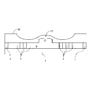
[0052] Fig. 8 is a cross-sectional view of a substrate incorporating a
sealed integrated
tube, in accordance with certain example embodiments. As can be seen in Fig.
8, the tube is
sealed. There is thus a bridge or cover 73 over the pocket 71. The pocket 71
is interior to the VIG
unit and is held at vacuum. In certain example embodiments, the cover 73 is
flush or
substantially flush with the shoulder portions of the substrate, as can be
appreciated from Fig. 8.
In certain example embodiments, the cover 73 is not flush with the outer
surface of the substrate
but does not protrude beyond it. In certain example embodiments, a structural
or non-structural
sealant material may be provided around the cover 73, e.g., to "fill in" any
recessed area relative
to the outer surface of the substrate.
[0053] In certain example embodiments, where an integrate tube is
provided, the
through-hole may be 0.5-5 mm in diameter or major distance, more preferably
1.5-4 mm in
diameter or major distance, and still more preferably 2-3.5 mm in diameter or
major distance. In
certain example embodiments, the tube sidewall thickness may be 0.2-0.5 mm
thick, more
preferably 0.25-0.45 mm thick.
[0054] The techniques of U.S. Patent No. 9,371,683 may be used to seal the
integrated
tube, e.g., by tracing smaller and smaller circles or other connected patterns
around the tube
proximate to the sidewall(s) / sealing arm(s) so as to cause opposing edges of
the sidewall(s) /
sealing arm(s) to sag towards one another and form a bridge (e.g., as shown in
Fig. 8). In cases
where multiple separate sidewalls / sealing arms are provided, progressive
scans of narrower
width may be used to similar effect. For instance, one or more lasers may be
used to scan along
first and second upwardly projecting sealing arms to cause them to sag towards
one another. The
laser(s) may be focused along scan lines
16
CPST Doc: 516132.1
Date Recue/Date Received 2023-08-09
CA 03125404 2021-06-29
WO 2020/141491
PCT/IB2020/050053
or scan areas that are increasingly close to one another, e.g., as the sag
continues to develop in the formation of the bridge.
100551 Fig. 9 is a flowchart showing an example process for making a
VIG unit in connection with an integrated pump-out tube, in accordance with
certain example embodiments. In step S81, the integrated pump-out tube
profile is formed in the first substrate, e.g., via one or more drilling
operations
or the like. Spacers or pillars are placed on the second substrate in step
S83. In
step S85, frit material is applied to peripheral edges of the second
substrate.
The first and second substrates are booked together in step S87 so that a
cavity
is formed therebetween, and a hermetic edge seal is formed in step S89 (e.g.,
via laser heating, heating in an oven, using infrared heaters, and/or the
like).
The cavity is evacuated to a pressure less than atmospheric in step S91. The
integrated tube optionally is pre-heated in step S93, e.g., while maintaining
the
vacuum. This may be accomplished using an oven, using infrared heaters, via
a laser, etc. Core heating is performed in step S95, and chase heating is
performed in step S97 repeatedly until a sealed (e.g., as indicated in step
S99).
The core heating process of step S95 provides the bulk of the melting process,
whereas the chase heating of step S97 is provided at progressively smaller
circumferences, areas, and/or the like, e.g., depending on the configuration
of
the sidewall(s) / sealing arm(s), the through-hole, the developing sag, etc.
Once sealed, the unit may be moved for further processing in step S101.
100561 It will be appreciated that the steps in the Fig. 9 and example
process may be performed in any suitable order, by different parties, and/or
that
further steps may be provided in different example embodiments. For instance,
different parties may form the hole compared to parties who seal the VIG
and/or port. In certain example embodiments, a tube profile will be formed in
the first substrate, the first and/or second substrate may be tempered, frit
may
be applied to the peripheral edges of the first and/or second substrate,
spacers
may be placed, and then other operations may be performed, e.g., as shown in
Fig. 9.
17
CA 03125404 2021-06-29
WO 2020/141491
PCT/IB2020/050053
[0057] Fig. 10 is an assembled VIG unit made in accordance with certain
example embodiments. The first substrate 32' includes the cover or bridge 73
resulting from the integrated pump-out tube as described above. The first and
second substrates 32', 2 are hermetically sealed together via the frit-based
edge
seal 4 and are held in substantially parallel spaced apart relation via
pillars 5
such that a gap or cavity 6 is defined therebetween.
[0058] It will be appreciated that techniques disclosed herein may be
used in a wide variety of applications including for example, in VIG window
applications, merchandizers, laminated products, hybrid VIG units (e.g., units
where a substrate is spaced apart from a VIG unit via a spacer system), etc.
[0059] The terms "heat treatment" and "heat treating" as used herein
mean heating the article to a temperature sufficient to achieve thermal
tempering and/or heat strengthening of the glass inclusive article. This
definition includes, for example, heating a coated article in an oven or
furnace
at a temperature of at least about 550 degrees C, more preferably at least
about
580 degrees C, more preferably at least about 600 degrees C, more preferably
at least about 620 degrees C, and most preferably at least about 650 degrees C
for a sufficient period to allow tempering and/or heat strengthening. This may
be for at least about two minutes, or up to about 10 minutes, in certain
example
embodiments. These processes may be adapted to involve different times
and/or temperatures.
[0060] As used herein, the terms "on," "supported by," and the like
should not be interpreted to mean that two elements are directly adjacent to
one
another unless explicitly stated. In other words, a first layer may be said to
be
"on" or "supported by" a second layer, even if there are one or more layers
therebetween.
[0061] In certain example embodiments, a method of making a vacuum
insulating glass (VIG) unit is provided. First and second glass substrates are
provided. An integrated pump-out tube is formed in the first substrate such
that, when viewed in cross-section, the first glass substrate includes (a)
first and
18
CA 03125404 2021-06-29
WO 2020/141491
PCT/IB2020/050053
second channel portions provided adjacent to opposite sides of a through-hole
and (b) first and second sealing wall portions defined therebetween. The first
and second substrates are sealed together in connection with an edge seal
provided around peripheral edges of the first and/or second substrates, a
cavity
being defined by the first and second substrates, and a plurality of spacers
being provided between the first and second substrates in the cavity and
helping to maintain the first and second substrates in substantially parallel,
spaced-apart relation to one another. The cavity is evacuated to a pressure
less
than atmospheric. The first and second sealing wall portions are
preferentially
heated to cause them to sag together and form a bridge covering the through-
hole and hermetically sealing the VIG unit.
100621 In addition to the features of the previous paragraph, in
certain
example embodiments, the channel portions may be formed to be parts of a
single channel surrounding the through-hole and/or the sealing wall portions
are formed to be parts of a single sealing wall surrounding the through-hole.
100631 In addition to the features of either of the two previous
paragraphs, in certain example embodiments, the channel portions may be
formed to at least initially be substantially U-shaped, substantially semi-
circular, substantially trapezoidal, and/or the like, when viewed in cross-
section.
100641 In addition to the features of any of the three previous
paragraphs, in certain example embodiments, the channel portions may be
formed via drilling.
100651 In addition to the features of any of the four previous
paragraphs,
in certain example embodiments, the preferential heating may include a core
heating phase to substantially melt the sealing wall portions, followed by
laser
heating that causes the first and second sealing wall portions to sag together
and form the bridge.
100661 In addition to the features of any of the five previous
paragraphs,
in certain example embodiments, the preferential heating may be laser heating,
19
CA 03125404 2021-06-29
WO 2020/141491
PCT/IB2020/050053
e.g., performed such that the laser heating includes tracing the sealing wall
portions as they sag towards one another in forming the bridge.
[0067] In certain example embodiments, a method of making a vacuum
insulating glass (VIG) unit is provided. The method comprises having first and
second glass substrates, the first substrate including an integrated pump-out
tube therein, the first substrate, when viewed in cross-section, including (a)
first
and second channel portions provided adjacent to opposite sides of a through-
hole and (b) first and second sealing wall portions defined therebetween. The
first and second substrates are sealed together in connection with an edge
seal
provided around peripheral edges of the first and/or second substrates, a
cavity
being defined by the first and second substrates, and a plurality of spacers
being provided between the first and second substrates in the cavity and
helping to maintain the first and second substrates in substantially parallel,
spaced-apart relation to one another. The cavity is evacuated to a pressure
less
than atmospheric. The first and second sealing wall portions are heated to
cause them to sag together and form a bridge covering the through-hole and
hermetically sealing the VIG unit.
[0068] In addition to the features of the previous paragraph, in
certain
example embodiments, the channel portions may be formed to be parts of a
single channel surrounding the through-hole and/or the sealing wall portions
may be formed to be parts of a single sealing wall surrounding the through-
hole.
[0069] In addition to the features of either of the two previous
paragraphs, in certain example embodiments, the channel portions may be
formed via drilling.
[0070] In addition to the features of any of the three previous
paragraphs, in certain example embodiments, the heating may include a first
heating phase to substantially melt the sealing wall portions, followed by a
second heating phase that causes the first and second sealing wall portions to
sag together and form the bridge. For instance, the second heating phase may
CA 03125404 2021-06-29
WO 2020/141491
PCT/IB2020/050053
be practiced using a laser and optionally may involve tracing the sealing wall
portions as they sag towards one another in forming the bridge.
[0071] In addition to the features of any of the four previous
paragraphs,
in certain example embodiments, the heating is laser heating.
[0072] In certain example embodiments, a method of making a vacuum
insulating glass (VIG) unit subassembly is provided. A first glass substrate
is
provided. An integrated pump-out tube is formed in the first substrate such
that, when viewed in cross-section, the first glass substrate includes (a)
first and
second channel portions provided adjacent to opposite sides of a through-hole
and (b) first and second sealing wall portions defined therebetween. Following
the forming of the integrated pump-out tube, the first substrate is forwarded
to
another party to: seal together the first substrate with a second substrate,
in
connection with an edge seal provided around peripheral edges of the first
and/or second substrates, a cavity being defined by the first and second
substrates, and a plurality of spacers being provided between the first and
second substrates in the cavity and helping to maintain the first and second
substrates in substantially parallel, spaced-apart relation to one another;
evacuate the cavity to a pressure less than atmospheric; and heat the first
and
second sealing wall portions to cause them to sag together and form a bridge
covering the through-hole and hermetically sealing the VIG unit.
[0073] In addition to the features of the previous paragraph, in
certain
example embodiments, the channel portions may be formed via drilling.
[0074] In addition to the features of either of the two previous
paragraphs, in certain example embodiments, the channel portions may be
formed to be parts of a single channel surrounding the through-hole and/or the
sealing wall portions may be formed to be parts of a single sealing wall
surrounding the through-hole.
[0075] Certain example embodiments relate to a vacuum insulating glass
(VIG) unit made by the method of any of the 14 previous paragraphs.
21
CA 03125404 2021-06-29
WO 2020/141491
PCT/IB2020/050053
Similarly, certain example embodiments relate to a first substrate provided in
accordance with any of the 14 previous paragraphs.
100761 In certain example embodiments, a substrate for use in a vacuum
insulating glass (VIG) unit, comprises an integrated pump-out tube in the
substrate such that, when viewed in cross-section, the first glass substrate
includes (a) first and second channel portions provided adjacent to opposite
sides of a through-hole and (b) first and second sealing wall portions defined
therebetween.
100771 In certain example embodiments, a vacuum insulating glass
(VIG) unit comprises first and second glass substrates maintained in
substantially parallel, spaced apart relation to one another via a hermetic
edge
seal and a plurality of spacers disposed in a cavity defined between the first
and
second glass substrates, the cavity being evacuated to a pressure less than
atmospheric using a plugless pump-out port hermetically sealed with a glass
bridge melted from a portion of the first glass substrate surrounding the
plugless pump-out port.
100781 While the invention has been described in connection with what
is presently considered to be the most practical and preferred embodiment, it
is
to be understood that the invention is not to be limited to the disclosed
embodiment, but on the contrary, is intended to cover various modifications
and equivalent arrangements included within the spirit and scope of the
appended claims.
22