Note : Les descriptions sont présentées dans la langue officielle dans laquelle elles ont été soumises.
CA 03126373 2021-07-09
WO 2020/144640
PCT/IB2020/050183
SYSTEM FOR LYOPHILIZING, RECONSTITUTING, AND DELIVERING A
MEDICATION, AND RELATED METHODS
CROSS-REFERENCE TO RELATED APPLICATIONS
The present application claims priority to U.S.
Provisional Application No. 62/791,182 filed on January 11,
2019, the entire contents of which are expressly incorporated
herein by reference.
TECHNICAL FIELD
The present invention relates to a modular system for
mixing two or more substances, such as liquids or powders. More
specifically, the present invention relates to a modular system
that can be used in lyophilizing, reconstituting, and delivering
a medication, and related methods of using the same.
BACKGROUND
Lyophilized medications are known in the art. Commonly,
the lyophilized medication is provided in a vial. To
reconstitute the medication, a healthcare provider typically
follows a multi-step process that includes: attaching a needle
to a syringe; drawing diluent from a vial into the syringe via
the needle; and injecting the diluent from the syringe into the
vial containing the lyophilized medication, thereby
reconstituting the medication. To deliver the medication after
reconstitution, the healthcare provider typically withdraws the
reconstituted medication from the vial via the syringe with
attached needle, and then injects the medication into an IV bag
or the patient. This process presents multiple opportunities
for the healthcare provider to unintentionally stick themselves
or others with the needle. There is a need in the art for
systems and methods for lyophilizing, reconstituting, and
1
CA 03126373 2021-07-09
WO 2020/144640
PCT/IB2020/050183
delivering a medication that overcome these and other
disadvantages of the prior art.
BRIEF SUMMARY
According to an embodiment of the disclosure, a modular
syringe assembly can include: a tubular syringe barrel having a
proximal end and a distal end, the tubular syringe barrel
defining a longitudinal axis; a plunger slidable within the
tubular syringe barrel; and a cap assembly including a stopper
portion and a Luer tip, the stopper portion receivable in the
distal end of the tubular syringe barrel, the stopper portion
defining a vent window. The cap assembly can be slidable
within the tubular syringe barrel along the longitudinal axis
between a sealed position where the vent window is covered by
the tubular syringe barrel to prevent venting between the cap
assembly and the tubular syringe barrel, and a vented position
where the vent window forms a vent between the cap assembly and
the tubular syringe barrel.
According to another embodiment, a method of lyophilizing
a medication can include: providing a modular syringe assembly
containing the medication, the modular syringe assembly
including a tubular syringe barrel, a plunger slidable within
the tubular syringe barrel, and a cap assembly movable on the
tubular syringe barrel between a sealed position and a vented
position; lyophilizing the medication with the cap assembly in
the vented position, whereby vapor is vented through the cap
assembly; and moving the cap assembly from the vented position
to the sealed position.
According to yet another embodiment, a method of
reconstituting a lyophilized medication can include: providing a
modular syringe assembly containing the lyophilized medication,
the modular syringe assembly including a tubular syringe barrel,
a plunger slidable within the tubular syringe barrel, and a cap
2
CA 03126373 2021-07-09
WO 2020/144640
PCT/IB2020/050183
assembly including a Luer tip; coupling a plunger rod to the
plunger; coupling the Luer tip to a source of diluent; and
retracting the plunger rod to draw the diluent into the tubular
syringe barrel.
BRIEF DESCRIPTION OF THE DRAWINGS
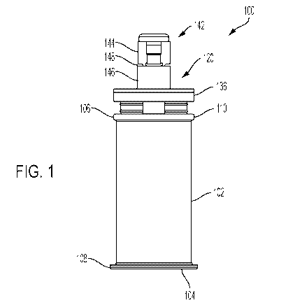
FIG. 1 is a side view of an embodiment of a modular
syringe assembly;
FIG. 2 is a perspective view of the modular syringe
assembly of FIG. 1;
FIG. 3 is an exploded view of the modular syringe assembly
of FIG. 1;
FIG. 4 is a side view of a portion of a cap assembly of
the modular syringe assembly of FIG. 1;
FIG. 5 is a bottom view of the portion of the cap assembly
of FIG. 4;
FIG. 6 is a side, cross-sectional view of the modular
syringe assembly of FIG. 1, shown with the cap assembly in a
vented position;
FIG. 7 is a side, cross-sectional view of the modular
syringe assembly of FIG. 1, shown with the cap assembly in a
sealed position;
FIG. 8 is an exploded view of an alternative embodiment of
the modular syringe assembly of FIG. 1;
FIG. 9 is an exploded view of another alternative
embodiment of the modular syringe assembly of FIG. 1;
FIG. 10 is a perspective view of the modular syringe
assembly of FIG. 1 in combination with a compression jig;
FIG. 11 is a side cross-sectional view of the compression
jig of FIG. 10;
FIG. 12 is a perspective view of the modular syringe
assembly of FIG. 1 with a plunger rod coupled thereto;
3
CA 03126373 2021-07-09
WO 2020/144640
PCT/IB2020/050183
FIG. 13 is a flow diagram of an embodiment of a method of
lyophilizing a medication;
FIG. 14 is a side view of the modular syringe assembly of
FIG. 12 coupled to an IV bag;
FIG. 15 is a side view of the modular syringe assembly of
FIG. 12 coupled to a vial via a vial adaptor;
FIG. 16 is a side view of the modular syringe assembly of
FIG. 12 coupled to a needle inserted into a vial;
FIG. 17 is a perspective view of the modular syringe
assembly of FIG. 12 coupled to a needle;
FIGS. 18A, 18B, and 18C depict perspective, side, and
lateral cross-sectional views of an embodiment of a plunger;
FIGS. 19A, 19B, and 19C depict perspective, side, and
lateral cross-sectional views of another embodiment of the
plunger; and
FIGS. 20A, 20B, and 20C depict perspective, side, and
lateral cross-sectional views of yet another embodiment of the
plunger.
DETAILED DESCRIPTION
All publications, including but not limited to patents and
patent applications, cited in this specification are herein
incorporated by reference as though fully set forth.
As used herein and in the claims, the singular forms "a,"
"and," and "the" include plural reference unless the context
clearly dictates otherwise.
The present application relates to a modular syringe
assembly that can be used to combine two or more substances,
such as liquids or powders. In a specific implementation, the
modular syringe assembly can be used with a lyophilized
medication. The modular syringe assembly can be transformed
among a variety of different configurations that can permit the
modular syringe assembly to be used during the lyophilization,
4
CA 03126373 2021-07-09
WO 2020/144640
PCT/IB2020/050183
reconstitution, and/or delivery of the medication. By utilizing
a modular syringe assembly during some or all of the foregoing
steps, the risk of needle sticks associated with conventional
processing of lyophilized medications (which often use a needle
to transfer the medication between various containers) can be
reduced or eliminated.
Referring to FIGS. 1-3, an embodiment of a modular syringe
assembly 100 is shown. FIG. 1 is a side view of the modular
syringe assembly 100. FIG. 2 is a perspective view of the
modular syringe assembly 100. FIG. 3 is an exploded view of the
modular syringe assembly 100. The modular syringe assembly 100
can include a tubular syringe barrel 102. The tubular syringe
barrel 102 can define a longitudinal axis A, shown in FIG. 3.
The tubular syringe barrel 102 can define a hollow interior
portion for containing the medication, and can include a
proximal end 104 and a distal end 106, both of which are open.
A protruding lip 108 can be provided at the proximal end 104.
The protruding lip 108 can facilitate attachment of a finger
grip to the tubular syringe barrel 102. A protruding lip 110
can be provided at the distal end 106. The tubular syringe
barrel 102 can be made of glass, plastic, or other suitably
durable materials known in the art. For example, and without
limitation, the tubular syringe barrel 102 can be made of
borosilicate glass, polypropylene, crystal zenith, Makrolon RX,
or polycarbonate.
Referring to FIG. 3, the modular syringe assembly 100 can
include a plunger 112 that is slidable within the tubular
syringe barrel 102. In the embodiment of FIG. 3, the plunger
112 comprises a rigid plunger base 114 having a rubber plunger
tip 116 coupled thereto, however, in alternative embodiments,
the rigid plunger base 114 can be omitted and the plunger 112
can be formed entirely of a pliable material such as rubber.
The plunger 112 can slide within and form a seal to the interior
CA 03126373 2021-07-09
WO 2020/144640
PCT/IB2020/050183
of the tubular syringe barrel 102. Referring to FIGS. 6 and 7,
embodiments of the plunger 112 can include a coupling 118 for
connection to a removable plunger rod (not shown). For example,
the coupling 118 can comprise a female thread or quarter-turn
cam configured to receive a male counterpart on the plunger rod,
or vice versa. According to embodiments, and without
limitation, the rigid plunger base 114 can be formed of
polypropylene, crystal zenith, Makrolon RX, or polycarbonate.
According to embodiments, and without limitation, the plunger
tip 116 can be formed of bromobutyl rubber.
Referring back to FIGS. 1-5, the modular syringe assembly
100 can further include a cap assembly 120 that attaches to the
distal end 106 of the tubular syringe barrel 102. Referring to
FIGS. 4 and 5, the cap assembly 120 can include a stopper
portion 122 and a Luer tip 124. The stopper portion 122 and
Luer tip 124 can be co-molded parts, or alternatively, can be
separate parts joined together, for example, by bonding. The
stopper portion 122 can have an outer diameter that allows it to
slide within the distal end 106 of the tubular syringe barrel
102, while forming a seal with the tubular syringe barrel 102.
As shown in FIG. 4, the stopper portion 122 can include ribs 126
or other surface features to form a seal with the tubular
syringe barrel 102, yet provide for a sliding interface
therewith. As best seen in FIGS. 4 and 5, the stopper portion
122 can define a vent window 128.
Referring to FIGS. 6 and 7, the modular syringe assembly
is shown in longitudinal cross-section. The cap assembly 120 is
slidable with respect to the tubular syringe barrel 102 along
the longitudinal axis A (FIG. 3) between a vented position shown
in FIG. 6 and a sealed position shown in FIG. 7. In the vented
position of FIG. 6, the cap assembly 120 is raised up from the
distal end 106 of the tubular syringe barrel 102. In this
position, the vent window 128 forms a vent passage between the
6
CA 03126373 2021-07-09
WO 2020/144640
PCT/IB2020/050183
stopper portion 122 and the tubular syringe barrel 102, allowing
vapor to escape from within the tubular syringe barrel 102 into
the ambient. In the sealed position of FIG. 7, the vent window
128 is covered by the tubular syringe barrel 102, thereby
blocking airflow between the tubular syringe barrel 102 and the
cap assembly 120 (and obstructing venting between the interior
of the tubular syringe barrel 102 and the ambient). With the
cap assembly 120 in the sealed position and the plunger 112 in
the tubular syringe barrel 102, the space between the cap
assembly 120 and the plunger 112 is sealed. A medication, such
as lyophilized medication, can be located in the tubular syringe
barrel 102 in the sealed space between the cap assembly 120 and
plunger 112, as will be described in more detail below. An
example of a lyophilized medication can include infliximab.
Referring specifically to FIG. 4, the stopper portion 122
includes a distal end 130 and a proximal end 132 opposed to the
distal end 130. The distal end 130 can define a flange 134, for
example, that projects radially from the stopper portion 122.
According to embodiments, the vent window 128 can be spaced
apart from the distal end 130, and can intersect with the
proximal end 132. As best seen in FIG. 3, a seal ring 136, such
as a gasket, can be located around the stopper portion 122.
When the cap assembly 120 is in the sealed position of FIG. 7,
the seal ring 136 can be sandwiched between the flange 134 and
the distal end 106 of the tubular syringe barrel 102, as shown
in FIG. 7. When the cap assembly 120 is in the vented position
of FIG. 6, the cap assembly 120 can be raised up such that the
flange 134 is spaced apart from the seal ring 136 and/or the
seal ring 136 is spaced apart from the distal end 106 of the
tubular syringe barrel 102. According to embodiments omitting
the seal ring 136, the flange 134 can be spaced apart from the
distal end 106 of the tubular syringe barrel 102 when in the
vented position, and the flange 134 can contact the distal end
7
CA 03126373 2021-07-09
WO 2020/144640
PCT/IB2020/050183
106 of the tubular syringe barrel 102 when in the sealed
position. Referring to FIGS. 3 and 7, a crimp ring 138 can be
placed over the flange 134 to retain the cap assembly 120 in the
sealed position. The protruding lip 110 on the distal end 106
of the tubular syringe barrel 102 can aid in retention of the
crimp ring 138.
Referring to FIGS. 1-3, the cap assembly 120 can further
include a Luer tip 124. According to embodiments, the Luer tip
124 can be co-molded with the stopper portion 122 (see FIG. 6),
however, other embodiments are possible. For example, the Luer
tip 124 and the stopper portion 122 can comprise a molded
plastic part, however, other embodiments are possible as will be
described below. According to embodiments, and without
limitation, the Luer tip 124 and/or stopper portion 122 can be
formed of polypropylene, crystal zenith, Makrolon RX, or
polycarbonate.
Still referring to FIGS. 1-3, an OVS closure 142 (e.g.,
manufactured by Vetter Pharma of Ravensburg, Germany) can be
provided on the Luer tip 124. The OVS closure 142 can snap onto
the Luer tip 124. The OVS closure 142 can include a primary
closure 144 and a threaded portionl 146 joined by a frangible,
tamper-evident seal 148 (see FIG. 1). In use, the tamper-
evident seal 148 can be broken by a user to allow removal of the
primary closure 144 and thereby expose the Luer tip 124 and the
threaded portion 146 of the OVS closure 142. As will be
described in more detail below, another component can be coupled
to the Luer tip 124 and threaded portion 146 for dispensing of
the contents of the modular syringe assembly 100. For example,
an EZ-Fill Integrated Tip Cap from Ompi, Stevanato Group of
Newtown, Pennsylvania, USA can be used.
FIG. 8 is an exploded view of an alternative embodiment of
the modular syringe assembly 100. The embodiment of FIG. 8 is
the same as FIGS. 1-7 except for the differences described
8
CA 03126373 2021-07-09
WO 2020/144640
PCT/IB2020/050183
below. According to the embodiment of FIG. 8, the sealing ring
136 can fit radially between stopper portion 122 and the inner
wall of the distal end 106 of the tubular syringe barrel 102,
forming a seal between. In this embodiment, the sealing ring
136 can also include a flange 150 that is sandwiched between the
distal end 106 of the tubular syringe barrel 102 and the flange
134 on the stopper portion 122 when the cap assembly 120 is in
the sealed position. Additionally, the vent window 128 can be
located in the sealing ring 136. Accordingly, the sealing ring
136 can be moved upwards and downwards with respect to the
distal end 106 of the tubular syringe barrel 102 to adjust
whether the cap assembly is in the sealed or vented position.
According to the embodiment of FIG. 8, the stopper portion 122
can be a relatively rigid plastic item, and the sealing ring 136
can comprise a relatively flexible rubber or plastic item that
promotes sealing between the stopper portion 122 and the tubular
syringe barrel 102.
FIG. 9 is an exploded view of yet another alternative
embodiment of the modular syringe assembly. The embodiment of
FIG. 9 is the same as FIGS. 1-7 except for the differences
described below. In the embodiment of FIG. 9, the seal ring can
be omitted. Additionally or alternatively, the stopper portion
122, flange 134, and Luer tip 124 can be co-molded from a rubber
material. As shown, the vent window 128 can be co-molded into
the stopper portion 122. According to embodiments, and without
limitation, the stopper portion 122, flange 134, and/or the Luer
tip 124 can be co-molded: the stopper and flange from bromobutyl
rubber, the Luer tip from polypropylene, Crystal zenith,
Makrolon RX, or Polycarbonate.
FIG. 10 is a perspective view of the modular syringe
assembly 100 of FIG. 1 in combination with a compression jig
160. FIG. 11 is a side cross-sectional view of the compression
jig 160 of FIG. 10. The compression jig 160 can be used to
9
CA 03126373 2021-07-09
WO 2020/144640
PCT/IB2020/050183
apply pressure on the cap assembly 120 to press it into the
distal end 106 of the tubular syringe barrel 102, for example,
to move the cap assembly 120 from the vented position to the
sealed position. The pressure can be applied to the compression
jig 160 by a machine surface, such as, for example, a
lyophilization shelf or other movable surface. The compression
jig 160 can have a geometry that mates with the cap assembly 120
in a manner that eliminates pressure upon the OVS closure 142,
reducing the chances of the OVS closure 142 or parts of the cap
assembly 120 from becoming damaged as the cap assembly 120 is
moved into the sealed position.
As shown in FIG. 11, for example, the compression jig 160
can include a first cavity 162 and a second cavity 164 separated
by a contact surface 166. The first cavity 162 can define an
inner diameter that permits the first cavity 162 to pass over
the cap assembly 120 and distal end 106 of the tubular syringe
barrel 102. According to embodiments, the inner diameter of the
first cavity 162 can also provide a clearance for vapor from the
vent window 128 to pass between the compression jig 160 and the
modular syringe assembly 100. The second cavity 164 can define
an inner diameter that permits it to pass over the OVS closure
142. The contact surface 166 can comprise a substantially
traverse surface that rests on the upper surface of the cap
assembly 120 to apply pressure from the compression jig 160 onto
the cap assembly 120. According to an embodiment, the inner
diameter of the second cavity 164 can be smaller than the inner
diameter of the first cavity 162. In use, the compression jig
160 can apply pressure onto the flange 134 via contact surface
166 of the cap assembly 120 to move the cap assembly 120 into
the distal end 106 of the tubular syringe barrel 102, e.g., to
move the cap assembly 120 from the vented position to the sealed
position. The second cavity 164 in the compression jig 160 can
serve as a relief for the OVS closure 142, thereby reducing or
CA 03126373 2021-07-09
WO 2020/144640
PCT/IB2020/050183
eliminating contact between the compression jig 160 and the OVS
closure 142. This can help reduce or eliminate the potential
for the OVS closure 142 and/or Luer tip 124 to be damaged as the
cap assembly 120 is moved into the sealed position. Although
the contact surface 166 is shown in FIG. 11 as being
substantially perpendicular to the axis of the first cavity 162
and the axis of the second cavity 164, other configurations are
possible provided the contact surface 166 can transmit
sufficient force to the cap assembly 120 to press it into the
distal end 106 of the tubular syringe barrel 102.
FIG. 12 is a perspective view of the modular syringe
assembly 100 of FIG. 1 with a plunger rod 168 coupled thereto,
e.g., removably coupled to the plunger 112.
FIG. 13 is a flow diagram of an embodiment of a method of
lyophilizing a medication. The method can be performed with the
embodiments of the modular syringe assembly 100 described
herein. In step 200, the plunger 112 can be inserted into the
tubular syringe barrel 102, for example, into the proximal end
104. The location of the plunger 112 within the tubular syringe
barrel 102 can be varied to account for different volumes of
medication to be lyophilized. For larger volumes, the plunger
112 can be located toward the proximal end 104, whereas for
smaller volumes, the plunger 112 can be spaced upward from the
proximal end 104.
Next, in step 202, the tubular syringe barrel 102 can be
filled with the medication to be lyophilized, for example, using
conventional laboratory equipment. An example of a medication
that can be lyophilized in the process is infliximab. According
to an embodiment, the proximal end 104 of the tubular syringe
barrel 102 can rest on the cooling shelf of a lyophilization
line during the filling step.
In step 204, the cap assembly 120 is inserted into the
distal end 106 of the tubular syringe barrel 102 and located in
11
CA 03126373 2021-07-09
WO 2020/144640
PCT/IB2020/050183
the vented position. According to various embodiments, step 200
can be performed before or after step 204, provided either the
plunger 112 or the cap assembly 120 is applied to the tubular
syringe barrel 102 before the medication is added. Once the
medication is contained in the tubular syringe barrel, it can be
lyophilized using conventional lyophilization equipment.
According to an embodiment, the lyophilization process can take
less than about 72 hours. With the cap assembly 120 in the
vented position, vapor released during the lyophilization
process can escape through the open vent window 128 in the cap
assembly 120.
In step 206, the cap assembly 120 is moved from the vented
position to the sealed position. For example, the cap assembly
120 can be pressed into the distal end 106 of the tubular
syringe barrel 102 until the flange 134 contacts the distal end
106 of the tubular syringe barrel 102. Alternatively, for
embodiments including a seal ring 136, the cap assembly 120 can
be pressed until the seal ring 136 is sandwiched between the
flange 134 and the distal end 106 of the tubular syringe barrel
102. In either case, when the cap assembly 120 is moved to the
sealed position, the tubular syringe barrel 102 seals off the
vent window 128, e.g., obstructs passage of air between the
interior of the tubular syringe barrel 102 and the ambient via
the vent window 128. An induction foil seal can be applied to
the proximal end 104 to further seal that end of the tubular
syringe barrel 102.
Step 206 can be performed by applying force to the cap
assembly 120 while holding the tubular syringe barrel 102 in
place, thereby displacing the cap assembly 120 into the distal
end 106 of the tubular syringe barrel 102. This can be done,
for example, by pressing on the cap assembly 120. According to
embodiments, this can be performed by applying force to the cap
assembly 120 using a conventional lyophilization shelf, however,
12
CA 03126373 2021-07-09
WO 2020/144640
PCT/IB2020/050183
other surfaces or structures can alternatively be used.
According to embodiments, force can be transmitted from the
lyophilization shelf to the cap assembly 120 via compression jig
160 located between the lyophilization shelf and cap assembly
120.
In step 208, the modular syringe assembly can be removed
from the lyophilization shelf and a crimp ring 138 can be
secured over the cap assembly 120 to seal the modular syringe
assembly 100 and the lyophilized medication contained therein.
This can be performed using conventional equipment.
Although the foregoing method was described above in
connection with a single modular syringe assembly 100, the same
method can be performed to simultaneously batch process multiple
modular syringe assemblies and their contained medications.
Still referring to FIG. 13, in step 210 a plunger rod 168
can be coupled to the plunger 112 to facilitate reconstitution
and/or delivery of the lyophilized medication. For example, the
plunger rod 168 can be coupled to the plunger 112 by securing a
threaded connection, cam-lock, or other connection between the
plunger rod 168 and plunger 112.
Embodiments of the present invention also include methods
of reconstituting and/or delivering a lyophilized medication.
To reconstitute the medication, the primary closure 144 can be
separated from the OVS closure 142 via frangible seal 148 to
reveal the Luer tip 124 of the cap assembly 120. The threaded
portion 146 of the OVS closure 142 can remain snapped onto the
Luer tip 124, and can be utilized to attach a source of diluent,
such as a water vial, to the Luer tip 124. The plunger rod 168
can then be retracted to draw the diluent into the tubular
syringe barrel 102 to thereby reconstitute the lyophilized
medication. The source of diluent can be decoupled from the
Luer tip, for example, by untwisting from the threaded portion
146. According to embodiments, and without limitation, the
13
CA 03126373 2021-07-09
WO 2020/144640
PCT/IB2020/050183
diluent can include water for injection (WFI), saline, or a
liquid custom formulated for the drug product. According to
embodiments, and without limitation, the source of diluent can
comprise a glass or plastic vial, bottle, or bag.
After reconstitution, the medication can be delivered via
the modular syringe assembly 100, for example, by pressing the
plunger rod 168. With reference to FIGS. 14-17, the Luer tip
can be attached, without limitation, to an IV bag 300 (FIG. 14),
a vial adaptor 302 attached to a vial 304 (FIG. 15), a needle
306 inserted into a vial 308 (FIG. 16), or a needle 310 (FIG.
17). Although not shown, according to other embodiments, one or
more of the modular syringe assemblies 100 can be placed in an
automated syringe pump or a customized device such as an
autoinjector to dispense the reconstituted medicine. The
devices can then be used to administer the reconstituted
medication to a patient using techniques known in the art.
FIGS. 18A-C, 19A-C, and 20A-C depict alternate embodiments
of the plunger 112 that can connect directly to a plunger rod,
e.g., without requiring the rigid plunger base 114 of FIG. 3.
In the embodiment of FIGS. 18A-C, the plunger 212 includes a
coupling 218 in the form of a cavity including threads adapted
to engage with corresponding threads on the distal end of a
plunger rod. In the embodiment of FIGS. 19A-C, the plunger 312
includes a coupling 318 in the form of a cavity including a
plurality of ribs adapted to engage with corresponding ribs on
the distal end of a plunger rod. The plunger 412 of FIGS. 20A-C
also includes a coupling 418 in the form of a ribbed cavity
including a rib to engage with ribs on the distal end of a
plunger rod. The coupling 318 of FIGS. 19A-C includes a
substantially flat top portion to receive a plunger rod having a
corresponding flat top. The coupling 418 of FIGS. 20A-C
includes a substantially dome-shaped top portion to receive a
plunger rod having a corresponding dome-shaped top.
14
CA 03126373 2021-07-09
WO 2020/144640
PCT/IB2020/050183
The rubber plungers 212, 312, 412 can also include a
plurality of ribs 212A, 312A, 412A, respectively, adapted to
form a seal between the plunger and the tubular syringe barrel
102. According to embodiments, and without limitation, the
plungers 212, 312, 412 can be formed of bromobutyl rubber.
According to alternate embodiments, various components of
the modular syringe assembly 100 can be colored, tinted, and/or
solid in color to protect light sensitive drug products.
According to further alternate embodiments, the modular syringe
assembly 100 can be used to combine two liquids or a powder and
liquid, or drug coated microspheres and liquid. According to
embodiments utilizing powder and microspheres, the powder and
microspheres can filled into the device with the liquid added
later as with a lyophilized drug, although alternative sequences
are possible depending upon existing process lines. According
to still further alternate embodiments, two of the modular
syringe assemblies 100 can be joined end to end with a male/male
adapter and used to transfer liquid from one to the other as in
the case of pre-filled syringes.