Note : Les descriptions sont présentées dans la langue officielle dans laquelle elles ont été soumises.
CA 03127125 2021-07-19
WO 2020/154814
PCT/CA2020/050116
TITLE: FINNED MOLD BLOCK
FIELD OF THE INVENTION:
The present invention relates to mold blocks used in pipe
corrugators and in particular, is directed to mold blocks with improved heat
dissipation and to pipe corrugators that use these improved mold blocks.
BACKGROUND OF THE INVENTION:
Opposed series of mold blocks are used in pipe corrugators to form
a moving mold tunnel. The opposed mold blocks come into abutment defining
a pipe mold cavity at an inlet to the moving mold tunnel and the mold blocks
separate at a downstream end of the mold tunnel. A thin envelope of extruded
plastic is introduced to the mold tunnel adjacent the inlet and drawn or
forced
into the mold cavity defined by the opposed mold blocks.
The mold blocks continue to move, preferably with a vacuum
source drawing the plastic into the mold cavity. A large portion of the pipe
corrugator is designed to cool the extruded plastic sufficiently such that the
formed pipe maintains its shape allowing the mold blocks to separate. Various
arrangements have been provided to efficiently remove heat from the mold
blocks and effectively remove heat from the partially formed extruded plastic
pipe.
A high rate of heat removal from the mold blocks is desirable as it
impacts other factors such as the length of the pipe corrugator. A certain
amount
of heat must be removed to cool the plastic to a suitable temperature prior to
the
mold blocks separating and returning to the inlet of the pipe corrugator. The
rate
of heat removal, the length of the pipe corrugator, the speed of the moving
mold
tunnel and the temperature of the atmosphere about the mold blocks are all
interrelated. Efficient heat removal can shorten the length of a corrugator
and
- 1 -
CA 03127125 2021-07-19
WO 2020/154814
PCT/CA2020/050116
reduce the cost thereof. In most situations, it is desirable to increase the
rate of
heat removal and it is also desirable to easily control the rate heat is
removed.
The mold blocks are typically made of a cast aluminum material
and are subsequently machined to provide the appropriate vacuum and cooling
channels, the finished faces for the mold cavity, as well as any provisions
for the
driving of the mold blocks along the length of the pipe corrugator.
Various cooling arrangements have been used to increase the rate
of heat removal from the mold blocks. Typically, these mold blocks include
vacuum ports in the mold cavity to draw the hot plastic into engagement with
the
mold faces of the mold blocks. Once the plastic has been shaped by the mold
face, the vacuum force can be reduced or eliminated. It has been known to use
these vacuum channels to supply cooling air into a gap between the molded
product and the pipe mold cavity. Basically, the molded plastic shrinks
somewhat as it is cooled, forming a gap relative to the mold cavity. Other
arrangements have provided cooling air flows through interior channel passages
of the mold blocks to remove heat therefrom. Water or liquid cooling of the
mold
blocks has many disadvantages typically associated with sealing and leakage.
It is also known to provide relatively thick ridge projections on the
exterior of the mold blocks to increase the dissipation of heat to the
surrounding
atmosphere due to the increased surface area and mass of the mold blocks. It
has
also been known to provide a cool controlled atmosphere about a portion of the
pipe corrugator to further increase or control the rate of heat removal.
It can further be appreciated that mold blocks with larger mass,
take longer to cool. Thus reducing the mass of the mold blocks provides an
increased rate of heat removal.
- 2 -
CA 03127125 2021-07-19
WO 2020/154814
PCT/CA2020/050116
The present invention allows for enhanced heat transfer from the
mold block to the surrounding atmosphere using a finned mold block design with
enhanced air flow.
SUMMARY OF THE INVENTION
A mold block for use in a pipe corrugator comprises a metal body
having an open mold cavity in a top side of the mold block with a base portion
of the mold block being configured to connect with a drive mechanism of the
pipe corrugator. Two opposed side portions of the mold block are adapted to
transfer heat of the mold block to the surrounding atmosphere primarily by
convection. These opposed side portions include cooling fins positioned on the
exterior of the mold block.
According to an aspect of the invention, the fins are orientated to
be generally parallel to a longitudinal axis of the mold cavity
In a further aspect of the invention, the mold block comprises a seal on the
split
face surface and a coupling apparatus located between the edge of the cooling
fins and the seal.
In a further aspect of the invention, the fins are of different depths
and the fins progressively increase in depth from a split surface on the top
side
of the mold block towards the base portion of the mold block. Preferably the
free ends of each series of fins on a side of the mold block align in a common
plane.
In a further aspect of the invention, the gap between adjacent fins
is 1 to 3 times as wide as the thickness of one of the fins.
In a further aspect of the invention, the gap between adjacent fins
is 1 to 2 times as wide as the thickness of one of said fins.
- 3 -
CA 03127125 2021-07-19
WO 2020/154814
PCT/CA2020/050116
In a further aspect of the invention, the split mold block further
comprises a thick top fin and a base 12 each having an outward edge. The fins
are configured such that an outward edge of each of said fins is inset of the
outward edge of each of the thick top fin and said base to protect the fins
from
damage.
According to an aspect of the invention, the cooling fins can also
include a series of connecting ports passing through the fins to enhance
airflow
movement across the fins and improve heat transfer during use of the mold
block.
In a further aspect of the invention, the connecting ports are
provided in the fins adjacent the junction of the fins to the metal body. This
arrangement reduces air stalling between the fins adjacent the metal body.
In a further aspect of the invention, a series of connecting ports are
provided in each mold block spaced in the length of the mold block with these
ports forming passages through a base portion of the fins. In this structure,
the
base portion of adjacent fins include airflow connecting ports allowing
airflow
to move into the gaps between adjacent cooling fins.
In a further aspect of the invention, the connecting ports include
connecting ports through the base portion. Preferably a vacuum source is
provided at the base portion of the mold blocks as they move through the mold
tunnel to further improve airflow across the fins.
BRIEF DESCRIPTION OF THE DRAWINGS
Preferred embodiments of the invention are shown in the Drawings
wherein:
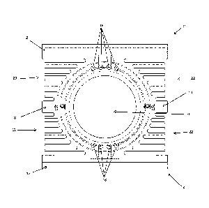
Figure 1A is an end view of a first embodiment of two opposed mold
blocks in abutment defining a pipe mold cavity;
- 4 -
CA 03127125 2021-07-19
WO 2020/154814
PCT/CA2020/050116
Figure 1B is an end view of a first embodiment of two opposed mold
blocks in a separated position;
Figure 2 is a top view of a single mold block a first embodiment looking
downwardly into the open mold cavity;
Figure 3 is a front side view of the mold block of Figure 2;
Figure 4 is a left side view of a mold block showing the sealing
arrangement;
Figure 5 is a side view of the seal showing both assembled and exploded
views;
Figure 6 is an end view of a second embodiment of two opposed mold
blocks in abutment defining a pipe mold cavity;
Figure 7 is a top view of a single mold block the second embodiment
looking downwardly into the open mold cavity;
Figure 8 is a front side view of the mold block of Figure 7;
Figure 9 is a bottom view of the second embodiment of the mold block;
and
Figure 10 is a graph showing mold block temperatures versus time for
conventional type mold blocks, an improved intermediary finned mold block and
a further improved mold block establishing proof of concept with respect to
improved heat dissipation.
DETAILED DESCRIPTION OF THE PREFERRED EMBODIMENTS
The follow description pertains to a finned mold block. More
particularly, two preferred finned mold blocks are described as examples. The
first example embodiment of the finned mold block is depicted in figures 1 to
3,
whereas the second example embodiment of the finned mold block is depicted
in figures 6 to 9.
The two opposed mold blocks of Figures 1A, 1B, and 6, are
orientated as a top mold block 2 and a bottom mold block 4, however it is also
- 5 -
CA 03127125 2021-07-19
WO 2020/154814
PCT/CA2020/050116
known that corrugators can have the mold blocks arranged as right and left
side
mold blocks.
The improved mold blocks will be described as top and bottom
mold blocks for convenience, however other orientations of the mold blocks can
be used and are included in the present invention. The top mold block 2 and
the
bottom mold block 4 cooperate to define the interior pipe molding cavity 6.
The
top mold block includes a split contact face 8 that abuts with split contact
face
of the bottom mold block to define part of the length of the pipe mold cavity
10 6. The abutting mold blocks move as a pair of mold blocks from an inlet
of a
pipe corrugator, through the length of the pipe corrugator and separate from
each
other at an exit of the pipe corrugator. Each of the mold blocks is then
returned
to an inlet of the pipe corrugator where the mold blocks again abut and
cooperate
with an extruder for receiving a thin envelope of plastic and drawing it into
the
pipe mold cavity.
Each of the mold blocks include a mold block base 12 for
cooperating with a drive of the corrugator. The mold blocks also include
vacuum
and/or cooling channels 16 that are provided in the mold block body 5 and
connect with the mold cavity 6. The finned mold block configuration improves
heat transfer from the mold blocks to the surrounding atmosphere. Each mold
block includes a first and a second bank of heat dissipating fins shown as 20
and
22 in FIG. 3. The heat dissipating fins are thin and elongated, extending
generally outwardly from the mold block body 5. The heat originates with the
extruded plastic and heat is thermally removed to set the plastic. This mold
block
design improves heat transfer and can be used to adjust or control the rate of
heat
transfer by varying the airflow across the fins. For many applications, the
main
advantage is the increased rate of heat transfer.
- 6 -
CA 03127125 2021-07-19
WO 2020/154814
PCT/CA2020/050116
Heat dissipation fins on mold blocks assist in heat transfer through
the mold blocks by conduction. The atmosphere provided exterior to the mold
block and in the channels between fins, allows for heat transfer from the mold
block to the atmosphere by convection. Heat transfer by conduction is more
efficient than heat transfer by convection and the rate of heat transfer by
convection is generally a function of the air movement or atmosphere movement
at and across the finned surfaces and the relative temperatures. If
pressurized air
is directed from the exterior of the mold block onto the sides of the mold
blocks,
further increases in the rate of heat transfer can be realized.
Much of the heat from the molded plastic is stalled in the mold
block body 5, located between the mold cavity 6 and the fins 20 and 22.
Reducing the mass of this portion of the mold block improves the heat
dissipation
from the mold block to the surrounding atmosphere. By including elongated,
thin fins with bases as close to the body 5 of the mold block and mold cavity
6
as possible, heat transfer is further increased. By providing the elongated
thin
fins, the gap between fins can extend further into the body 5 of the mold
block
than traditional mold block designs. With the elongated fins, the mass that
would
typically lie between adjacent fins is removed, thus decreasing the mass of
the
mold block and improving heat transfer. In a preferred embodiment, the bases
of the fins are configured to generally follow the radius of the mold cavity
to
allow for the base of all fins to be similar or the same horizontal distance
from
the mold block cavity.
When in abutment, mold block pairs are held relative to each other
using a pin and hold connection. One of the mold block pairs includes pins 15
extending outwardly from the split contact face, while the other mold block
includes a corresponding hole in the split contact face into which the at
least one
connecting pin can engage. At least one pin/hole pair is included on each side
of the mold block, however, it can be appreciated that more pins/hole
- 7 -
CA 03127125 2021-07-19
WO 2020/154814
PCT/CA2020/050116
arrangements could be used. This pin arrangement maintains the position of the
top mold block to the bottom mold block mold tunnel of the corrugator.
Traditionally, the pin and corresponding hole have been located on or in the
body
of the mold block. As a result, the mold block bodies have needed to be large
5 enough
to allow for the inclusion of a pin or corresponding hole and split contact
face seal.
In a preferred embodiment shown in Figures 1-3, the connecting
pin and corresponding hole 17 are located exterior to the split contact face
seal
41. There is at least one pin/hole pair on each side of the mold block. In
this
preferred embodiment, they are located at the inner edge or base of a top fins
29
and 31 which allows for the thickness of the body 5 to be reduced. The
preferably thicker top fins 29 and 31 along with the base 12, provide
structural
stability to the mold block to prevent twisting of the mold blocks during use.
By
providing relatively thin cooling fins adjacent the mold cavity on either side
of
the mold block, the overall mass of the mold block is reduced. In a preferred
embodiment, providing the fins adjacent the mold block allowed for a 20
percent
reduction in mass of the mold block when compared to traditional non-finned
designs.
Furthermore, it is preferred that exterior ends 33 and 35 of the heat
dissipating fins 20 and 22 respectively, are inset from the ends of the top
fins 29
and 31 and the base 12. Insetting the fins relative to the top fins 29 and 31
and
the base 12 provides protection to the fin banks 20 and 22.
Figure 4 shows a split contact face seal 41, typically made of a
flexible heat resistant tubing, such as silicon or rubber, although other
suitable
materials would be known to a person skilled in the art. To create a seal
between
the top mold block 2 and the bottom mold block 4, the tubular seal is placed
and/or secured in seal channels 43 located on the split contact face 10 of the
- 8 -
CA 03127125 2021-07-19
WO 2020/154814
PCT/CA2020/050116
bottom mold block. As the top and bottom mold block come into abutment and
vacuum is applied to pull the plastic into the mold blocks, this top seal
prevents
leakage of the vacuum pressure between the abutting top and bottom mold. In
this example, the bottom mold block included the seal channels 43, however it
can be appreciated that the top mold block could alternatively be configured
to
house the seal and seal channel.
A second seal 45 is located on a vertical face of the mold block.
When one mold block pair abuts the next mold block pair in the mold tunnel,
this second seal is compressed between adjacent faces of the two mold block
pairs. As can be seen in Figure 2, the second seal 45 fits into a second seal
channel 47. The second seal channel preferably runs from one side of a
vertical
face of the mold block to the second side of the vertical face of the mold
block
in a semi-circular manner which follows the general shape of the mold cavity.
However, it can be appreciated by a person skilled in the art that other seal
arrangements would be possible.
In order to connect the split contact face seal 41 to the second seal
45, a corner seal 49 is used. The corner seal 49 is preferably integrally or
monolithically formed and is coupled to the contact face seal 41 and second
seal
45 by a spigot. The spigot frictionally engages the interior of the tubular
seals
to keep adjacent seal portions coupled. By providing a corner seal 49, loss of
pressure or vacuum pressure between both the top and bottom mold block and
adjacent mold block pairs is reduced.
While the seal arrangement showing in Figures 4 and 5 are made
in 3 pieces, it can be appreciated that the split contact face seal 41, second
seal
45 and corner seal 49 could be formed as a single piece or as two pieces with
the
corner piece formed integrally with either the first seal 41 or second seal
45.
- 9 -
CA 03127125 2021-07-19
WO 2020/154814
PCT/CA2020/050116
In the preferred embodiment shown in Figure 2, the split contact
face seal 41 runs parallel to the sides, or fin ends, of the mold blocks. This
provides less movement of the seal and thus, less potential for leakage when
compared to alternative designs, as shown in Figure 7 which includes a
straight
middle portion with two side portions, each angled from the straight middle
portion towards to the front or back faces of the mold block.
A second embodiment of the finned mold block is shown in Figures
6 to 9. In this alternative embodiment, the heat dissipating fins also include
a
series of connecting ports 25 and 27 through the base of the fins to improve
airflow past and between the fins and in particular, improve airflow adjacent
the
base of the fins. By providing connecting ports 25 and 27 and the channel
portions 24 and 26, additional air movement across the heat dissipation fins
is
realized. If pressurized air is directed from the exterior of the mold block
onto
the sides of the mold blocks, further increases in the rate of heat transfer
can be
realized. Without the communication ports the air at the base of the fins is
restricted and may be generally stalled. By providing the communication ports,
airflow can move between the fins and provides a further escape route for any
air that is forced from the exterior of the mold block towards the mold block.
Having these ports and channels also lead through the base and exhaust through
transfer ports 29 and 31 also increases flow. Ports 29 and 31 can move over a
vacuum source as they move along a pipe corrugator to further improve flow.
This vacuum source can be adjusted manually or automatically to achieve a
desired result such as a temperature range of the mold blocks exiting the
molding
tunnel to provide a further control for operator or automatic adjustment.
As shown in FIG. 8, these communication channels 24 and 26
between fins are aligned and preferably formed by drilling passages through
the
mold block at an angle such that the drilled passage intersects with fins
adjacent
the base of the fins and the mold body 5. By providing the series of
- 10 -
CA 03127125 2021-07-19
WO 2020/154814
PCT/CA2020/050116
communication ports along the length of the mold block, improved air movement
across the fins can be realized.
Drilling of the passageways to form channels 24 and 26 is easily
accomplished and connecting of the base of adjacent fins using the connecting
ports has significantly improved the rate of heat transfer from the mold
blocks.
The base of the fins with the connecting ports allows for air
movement out of the gap between the fins to improve the rate of heat transfer
from the finned mold blocks to the surrounding atmosphere when compared to
traditional mold block designs.
While it can be appreciated that the thickness of the fins would vary
in accordance with the size of the mold block, in a preferred embodiment of
each
fin mold block design, each fin has a thickness of 3 to 5 mm. This range
provides
relatively strong fins which are desirable to avoid damage during use or
handling
of the mold blocks. The size of the gap between adjacent fins can also in
accordance with the size and properties of the mold block, however in a
preferred
embodiment, the gap is about 1 to 4 times the fin thickness. In a further
preferred
embodiment, the gap between adjacent fins is 1 to 2 times the fin thickness to
provide improved heat dissipation. Air can be forced or directed against the
open
ends of the fins of the mold blocks. In a design having connecting ports, such
as
the embodiment shown in figures 6 to 9, a vacuum assist can be provided
preferably through the base of the mold blocks.
Finned Mold Block Performance
The heat dissipation capabilities of the finned mold blocks has been
described with respect to forcing air or cooling airflow across the finned
mold
blocks from the sides of the mold blocks with the air moving across the fins
and
exiting at the base of the mold blocks or at least capable of exiting adjacent
the
- 11 -
CA 03127125 2021-07-19
WO 2020/154814
PCT/CA2020/050116
base of the mold blocks. The modified finned mold block with connecting ports
can be used in combination with an air pressure differential to enhance
airflow
movement across the fins.
The graph of mold block temperature versus time in Figurel 0
provides some preliminary data establishing proof of concept with respect to
improved heat transfer rates of the finned mold blocks. A standard mold block
without the opposed series of fins was compared to two finned mold blocks.
Each mold block was heated to a high temperature and then allowed to cool in
the presence of forced air.
The first set of data lines 100 shows a traditional mold block that
does not include the first and second bank of heat dissipating fins. The mold
block was heated to a temperature in the range of 175 F to 200 F and the time
required to drop this temperature to the range of 130 to 140 F was
approximately
7 minutes.
In contrast, the finned mold block set of data lines 102 illustrates
an improvement in the rate of heat dissipation. The thickness of the fins of
this
mold block were 3mm and the gap between fins was 6mm. The mold block was
raised to a temperature of 220 and 230 F and the time required to drop mold
blocks to less than 135 F was approximately 4 1/2 minutes.
A further improvement in heat dissipation of the mold blocks is
shown in the set of data lines 104. This mold block had fins 3mm thick with a
gap between fins of 3mm. The original temperature of the mold block was in
the order of 190 to 210 F and the temperature of this mold block was reduced
to
between 120 and 135 F within 3 minutes and 30 seconds. The individual line of
each set of data lines is based on heat sensors spaced along the mold block
and
measure a fin temperature.
- 12 -
CA 03127125 2021-07-19
WO 2020/154814
PCT/CA2020/050116
With respect to the two different fin mold blocks, the original
temperature of the mold blocks was higher yet the time to drop the mold block
temperature to the lower value was reduced from approximately 7 minutes to 4
minutes and 30 seconds in one case and 3 minutes and 30 seconds in another
case. In each of these examples the original temperature of the mold blocks
was
higher.
Both finned mold blocks had increased rates of heat transfer and
function well.
As shown by the relative performance lines of the graph of Figure
10, the improved finned mold blocks with connecting ports through the fins
significantly improve the ability to remove heat and/or adjust the rate of
heat
removal. For example, after the plastic of a molded product has initially set,
the
airflow across the fins can be increased to provide more cooling if needed.
Heat
removal has been described primarily during the forming operation; however, it
is also used to remove heat when mold blocks are returned from the exit of the
mold tunnel to the inlet to the mold tunnel.
Although preferred embodiments have been described in the
Detailed Description, the invention is not limited to the preferred structure
and
is defined by the following claims.
- 13 -