Note : Les descriptions sont présentées dans la langue officielle dans laquelle elles ont été soumises.
CA 03127358 2021-07-20
WO 2020/160424
PCT/US2020/016135
ELECTROCHEMICAL SYSTEM WITH CONFINED ELECTROLYTE
CROSS-REFERENCE TO RELATED APPLICATIONS
[0001] This Application claims the benefit of US Provisional Patent
Application
62/799,966, filed February 1, 2019, titled "Electrochemical System with
Confined
Electrolyte," and US Provisional Patent Application 62/854,757, filed May 30,
2019, titled
"Water Electrolyzers with Thermal Management Systems," each of which is
incorporated
herein by reference in its entirety to the extent not inconsistent herewith.
FIELD OF THE INVENTION
[0002] This invention generally relates to electrochemical systems and in
some
embodiments more particularly to cells, stacks, and operations of
electrochemical cells for
producing gaseous products.
BACKGROUND
[0003] Hydrogen in molecular form (H2) has been a valuable commodity for
many
decades. Uses typically include ammonia production, catalytic cracking of
hydrocarbons and
other industrial applications.
[0004] It has been recognized that hydrogen can also serve as an energy-
storage medium
and will play a role in the future energy economy. One expected method for use
of hydrogen
in this application is through injection into the natural gas grid where
enormous capacity for
the storage of energy in the form of hydrogen gas is already available. This
application is
called Power to Gas (P2G) or Green Hydrogen. As P2G and Green Hydrogen
technologies
proliferate, electric power consumed by electrolyzers will increase.
[0005] Existing electrolyzer systems have many shortcomings which result in
reduced
efficiency and increased system complexity leading to increased costs.
SUMMARY
[0006] Various embodiments will be described in detail with reference to
the
accompanying drawings. References made to particular examples and
implementations are
for illustrative purposes and are not intended to preclude the inclusion of
other
implementations. Various components, sub-systems, and modifications of the
various
embodiments may be re-combined with components, sub-systems, or modifications
of other
embodiments to form further embodiments.
1
CA 03127358 2021-07-20
WO 2020/160424 PCT/US2020/016135
[0007] Water electrolysis for the production of hydrogen and other gases is
currently
performed in systems of two types. Polymer electrolyte membrane (or proton
exchange
membrane, both abbreviated PEM) electrolyzers utilize a solid polymer
electrolyte to conduct
protons between positive and negative electrodes. Such systems generally
involve pumping
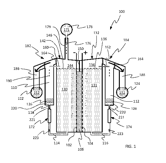
pure deionized water into a stack of cells, each containing a solid polymer
electrolyte. Solid
polymer electrolytes are generally very thin, historically allowing for higher
current density
operation with low resistance. Additionally, solid polymer electrolyte
membranes tend to
substantially limit the quantity of gas that crosses from one half-cell to the
other through the
membrane, resulting in higher gas purity and reduced losses.
[0008] However, solid polymer electrolytes also tend to be more resistive
to ionic
conductivity than liquid or gel electrolytes. The higher resistance leads to
increased
efficiency losses. PEM electrolyzers also tend to require costly materials
such as platinum-
group metal catalysts and titanium or gold support structures. As a result,
despite their
advantages, PEM electrolyzers can be quite expensive to build and operate.
[0009] The second type, alkaline electrolyzers, use an aqueous alkaline
electrolyte
solution to conduct ions between the electrodes across an electrically non-
conductive
separator. Alkaline electrolyzers benefit from lower cost materials and may
potentially
display improved performance owing to the highly conductive nature of the
electrolyte. As
compared with PEM electrolyzers, alkaline electrolyzers tend to be less
susceptible to gas
crossover. Nonetheless, alkaline electrolyzers remain susceptible to other
complications. One
of the most substantial shortcomings of alkaline electrolyzers is the
parasitic losses caused by
so-called "shunt currents."
[0010] In conventional state-of-the-art alkaline electrolyzers, the water
split in the
electrolysis reaction is the water in the aqueous electrolyte solution which
is pumped through
a cell stack. Circulating the electrolyte through the stacks provides various
benefits such as
exposing the electrodes to a well-mixed electrolyte solution, allowing for the
removal of
dissolved gases external to the cells, and allowing for simple maintenance of
hydroxide (or
other electrolyte) concentration.
[0011] Such alkaline electrolyte systems generally use a manifold or other
common
electrolyte flow channel to direct electrolyte into and through all cells of a
stack. These
common channels containing electrically conductive electrolyte create a
conductive path
between cells through which electric currents can flow. These "shunt currents"
do not support
2
CA 03127358 2021-07-20
WO 2020/160424 PCT/US2020/016135
the desired electrochemical reactions in the cells, and therefore represent a
form of
inefficiency sometimes referred to as a parasitic loss.
[0012] Most approaches to mitigating or eliminating shunt currents tend to
be minimally
effective, costly, or introduce further system inefficiencies. Nonetheless,
the costs and
inefficiencies imposed by shunt currents are widely accepted as the inevitable
cost of
operating an alkaline electrolyzer.
[0013] Applicants have taken a different approach to avoiding shunt
currents, and in the
process realized several other advantages. Instead of fighting the challenges
of a flowing
electrolyte system architecture, Applicants have developed an electrochemical
cell stack
architecture that eliminates the need for flowing electrolyte through an
entire cell stack by
integrating functions of the "balance of plant" into each layer of the cell-
stack. In such a
system, each cell or half-cell contains a quantity of electrolyte that is
confined within the cell
or half-cell and fluidically isolated from electrolyte in any other cells. The
electrolyte thus
confined is not capable of creating unwanted electrically conductive paths
with other cells
within the stack. As a result, parasitic shunt currents are avoided. The
avoidance of shunt
current provides for benefits unavailable to conventional alkaline
electrolyzers, such as the
ability to incorporate more cells within a single stack than is feasible in
conventional alkaline
electrolyzers, thereby achieving higher stack voltages and improving overall
efficiency. The
lack of flowing electrolyte also allows for improved gas purities by
mitigating forces tending
to cause gas produced in one half-cell to cross over into a counter-half-cell
(generally referred
to herein as "gas crossover" or simply "crossover").
[0014] Notwithstanding references herein to alkaline electrolysis systems,
the skilled
artisan will recognize that the devices, systems, and methods described herein
may be applied
to a wide range of electrochemical cells and systems, including various
chemical-producing
electrolyzers, battery systems, fuel cell systems, electrochemical systems for
purifying water,
materials, or chemicals, and other electrochemical cell systems.
[0015] The unique architecture described herein comprises several
components and sub-
systems, including an electrolyte confinement system for substantially
confining aqueous
electrolyte within each cell or half-cell; an electrolyte capture system for
capturing any
electrolyte that escapes the confinement system; an electrolyte return system
for returning
electrolyte that escapes a cell or half-cell back into the cell or half-cell
chamber; a passive
pressure-driven water supply system for supplying a make-up liquid (e.g.,
deionized water in
3
CA 03127358 2021-07-20
WO 2020/160424 PCT/US2020/016135
some embodiments) to the each cell or half-cell to replace liquid (e.g.,
water) consumed in
electrochemical reactions within the cell while substantially minimizing
pressure differences
across the separator membrane; a high-pressure gas collection system for
collecting produced
gases at high pressures without requiring external gas compression;; and a
volume expansion
system for accommodating volumetric expansion and contraction of fluids within
a cell.
[0016] Some embodiments of the subsystems above may also utilize a unique
pump
configuration referred to herein as a "ventricular" pump. Embodiments of
electrochemical
systems herein may also be configured to passively but automatically control
various pressure
regions and pressure gradients under active fluid pressure control at a
minimal number of
points within the system.
[0017] In some embodiments, an electrochemical system as described herein
may be
operated at a high absolute pressure while maintaining relative pressure-
differences between
various pressure regions within desired ranges. Operating a gas-producing
electrochemical
cell at a high absolute pressure may allow for gases to be produced and
delivered at high
pressures without the need (or with a reduced need) for additional compressors
to pressurize
gases to a pressure required by a particular application.
[0018] In various embodiments, an electrochemical system to be operated at
an elevated
pressure (i.e., at an absolute pressure greater than atmospheric pressure) may
include a cell-
stack and/or other structures within one or more pressure vessels or by using
a plate-and-
frame cell stack arranged to hold the desired degree of pressure relative to
atmospheric
pressure. In some embodiments, operating at a high absolute pressure may be
accomplished
by pre-pressurizing one or more cell regions with an inert or minimally-
reactive gas (e.g.,
nitrogen, argon, helium, neon, or various combinations of these or other
gases). In other
embodiments, a high operating pressure may be initially established and/or
maintained by
pumping a make-up liquid (e.g., water) into the cell-stack at a desired
absolute pressure. For
example, in some embodiments, an electrochemical system may be pre-pressurized
and
operated at an absolute pressure of about 10 bar, 20 bar, 30 bar, 40 bar, 50
bar, 60 bar, 70 bar,
80 bar, 90 bar, 100 bar, 10 atm, 20 atm, 30 atm, 40 atm, 50 atm, 60 atm, 70
atm, 80 atm, 90
atm, 100 atm or more.
[0019] In an aspect, provided is a stack of confined electrolyte
electrochemical cells, each
individual electrochemical cell independently comprising: a) a first half-cell
chamber
containing a first volume of electrolyte in contact with a first electrode; b)
a second half-cell
4
CA 03127358 2021-07-20
WO 2020/160424 PCT/US2020/016135
chamber containing a second volume of electrolyte in contact with a counter-
electrode; c) a
separator separating the first half-cell chamber from the second half-cell
chamber; and d) a
first electrolyte capture-and-return system in communication with the first
half-cell, the
electrolyte capture-and-return system configured to receive a captured
electrolyte from the
first volume of electrolyte escaping the first half-cell chamber and to drive
the captured
electrolyte back into at least one of the first half-cell chamber and the
second half-cell
chamber via an electrolyte return conduit. In embodiments, the capture-and-
return systems in
an individual electrochemical cell may be fluidically isolated from capture-
and-return
systems in the other electrochemical cells in the stack. In embodiments, the
stack may
comprise a bipolar stack comprising bipolar plates joining adjacent cells.
[0020] The electrochemical system may further comprise a second electrolyte
capture-
and-return system in communication with the second half-cell chamber, the
second
electrolyte capture-and-return system configured to capture electrolyte from
the second
volume of electrolyte escaping the second half-cell chamber and to drive the
captured
electrolyte back into the first half-cell chamber, the second half-cell
chamber or both.
[0021] The first and second electrolyte capture-and-return systems may
comprise a
liquid-gas separation chamber. The liquid-gas separation chamber may use
gravity to allow
for the capture of liquid electrolyte while having a headspace to allow for
the flow of gas,
including product gas. The first and second electrolyte capture-and-return
systems may be in
fluid communication with a gas removal manifold and the gas removal manifold
is in fluid
communication with each of the electrochemical cells in the stack. The first
and second
electrolyte capture-and-return systems may comprise a gas-removal liquid. The
gas removal
liquid may be maintained within a pre-determined range of fluid pressure.
[0022] The electrochemical system may further comprise a fluid escape
element through
which gas and liquid electrolyte escapes the first half-cell chamber or second
half-cell
chamber into the first electrolyte capture-and-return system or second
electrolyte capture-
and-return system, respectively. The fluid escape element may be configured to
impart a
resistance to fluid flow. The fluid escape element may be configured to impart
a non-linear
resistance to fluid flow, wherein the fluid comprises both gas and liquid. The
fluid escape
element may comprise an egress channel through which a bolus of gas and a
bolus of liquid
may only flow in series. A fluid escape element can comprise one or more
egress channels
and/or one or more membranes, according to embodiments described herein. In
some
CA 03127358 2021-07-20
WO 2020/160424 PCT/US2020/016135
embodiments, a fluid escape element can consist of one or more egress channels
and/or one
or more membranes, according to embodiments described herein.
[0023] The electrolyte capture-and-return system may comprise an
electrolyte capture
volume. The electrolyte capture-and-return system may comprise a membrane
positioned
between said half-cell and said electrolyte capture volume. The electrolyte
capture-and-return
system may comprise a membrane to promote the flow of product gas while
maintaining
electrolyte in the electrolyte capture-and-return system, for example,
positioned between a
product gas outlet and the electrolyte capture volume. The electrolyte capture-
and-return
system may comprise one or more pumps configured to return the electrolyte to
the first half-
cell or the second half-cell. The electrolyte capture-and-return system is
configured to allow
for mixing of the electrolyte, for example, between the two half-cells of an
electrochemical
cell.
[0024] The electrochemical system may be a battery, a flow battery or a
fuel cell. The
electrochemical system may be an alkaline electrolysis cell. The
electrochemical cell
generates hydrogen gas and oxygen gas as product gasses. The electrolyte may
be an aqueous
alkaline solution. The electrolyte may comprise potassium hydroxide, sodium
hydroxide,
lithium hydroxide or any combination thereof.
[0025] The electrochemical cell may further comprise an expansion chamber
in fluid
communication with the first half-cell and the second half-cell, the expansion
chamber being
configured to allow volumetric expansion of fluid in one or both of the half-
cell chambers as
gas bubbles in the electrolyte increase the volume of the mixed fluid. The
expansion chamber
is configured to reduce pressure gradients between the first half-cell and the
second half-cell.
The expansion chamber may maintain substantially equal pressure in the first
half-cell and
the second half-cell, for example, a difference in pressure of less than 2
atm, less than 1 atm,
less than 0.5 atm or optionally, less than 0.25 atm. The expansion chamber may
be in fluid
communication with the electrolyte capture-and-return system.
[0026] The electrochemical cell may further comprise an expansion resistor
in operable
communication with the expansion chamber. The expansion resistor may be a
spring, a
bellow, a diaphragm, a balloon, a physical property of the expansion chamber
or any
combination thereof. The expansion chamber may comprise a divider to maintain
separation
of the electrolyte from the first half-cell and the second half-cell. Such a
divider may also be
configured to allow fluid pressures in the two half-cells to equilibrate. The
expansion
6
CA 03127358 2021-07-20
WO 2020/160424 PCT/US2020/016135
chamber may impart a resistance to expansion causing an increase in fluid
pressure when the
expansion chamber volume exceeds a threshold volume. The expansion chamber may
impart
a resistance to expansion causing fluid pressure to increase linearly,
geometrically,
exponentially, stepwise, or otherwise with increasing expansion chamber
volume.
[0027] The electrochemical cell further comprises a make-up liquid supply
in fluid
communication with the electrochemical cell to provide make-up liquid to the
first half-cell,
the second half-cell, or both. The electrochemical system may further comprise
a one-way
valve positioned between the make-up liquid supply and the electrochemical
cell. The make-
up liquid supply may be provided to the electrochemical cell by a supply
manifold in fluid
communication with each electrochemical cell in the stack. The one-way valve
may regulate
the flow of make-up liquid into the electrochemical cell based on a pressure
differential
between the supply manifold and the electrochemical cell. The make-up liquid
may be
deionized water.
[0028] The electrochemical system may further comprise a pump, for example,
a
ventricular pump or a positive displacement pump, operably connected to each
of the
electrochemical cells and arranged to drive captured electrolyte from the
electrolyte capture
volume into one or both of the half-cell chambers. The pump may be capable of
driving both
liquid and gas through the electrolyte return channel. The pump may comprise a
compressible
section of conduit surrounded by an actuation fluid. Each electrochemical cell
in the stack
may comprise at least one compressible conduit section in a housing volume
exterior to the
electrochemical cell. Each half-cell chamber of each electrochemical cell in
the stack may
comprise a compressible conduit section in the housing volume. The actuation
fluid may be
contained in a continuous housing volume surrounding compressible conduit
sections of all
electrochemical cells.
[0029] The stack may be arranged in a prismatic layered configuration
(e.g., a plate-and-
frame configuration), a concentric cylindrical configuration, a spiral
jellyroll configuration, a
prismatic jellyroll configuration or any other rolled jellyroll configuration.
[0030] In an aspect, provided is an electrochemical system comprising: at
least one
confined electrolyte electrochemical cell comprising: a) the electrolyte; b) a
first half-cell
comprising a first electrode in contact with first portion of the electrolyte
and a first
electrolyte capture-and-return system; c) a second half-cell comprising a
second electrode in
contact with a second portion of the electrolyte and a second electrolyte
capture-and-return
7
CA 03127358 2021-07-20
WO 2020/160424 PCT/US2020/016135
system; and d) a separator separating the first half-cell from the second half-
cell; wherein the
first electrolyte capture-and-return system is configured to capture the
electrolyte displaced
from the first half-cell and return at least a portion of the displaced
electrolyte to the first
half-cell without mixing with electrolyte from any other cell; and wherein the
second
electrolyte capture-and-return system is configured to capture electrolyte
displaced from the
second half-cell and return at least a portion of the displaced electrolyte to
the second half-
cell without mixing with electrolyte from any other cell.
[0031] The first electrolyte capture-and-return system may be fluidically
isolated from
the second half-cell and wherein the second electrolyte capture-and-return
system may be
fluidically isolated from the first half-cell.
[0032] In an aspect, provided is a method of generating at least one
product gas
comprising: i) providing an electrochemical system comprising: at least one
electrochemical
cell comprising: a) an electrolyte; b) a first half-cell having a first
electrode in communication
with first portion of the electrolyte and a first electrolyte capture-and-
return system; c) a
second half-cell including a second electrode in communication with a second
portion of the
electrolyte and a second electrolyte capture-and-return system; and d) a
separator separating
the first half-cell from the second half-cell; ii) capturing at least a
portion of electrolyte
displaced from the first half-cell via a first electrolyte capture-and-return
system and
returning the captured electrolyte to the first half-cell; iii) capturing at
least a portion of
electrolyte displaced from the second half-cell via a second electrolyte
capture-and-return
system and returning the captured electrolyte to the second half-cell; and iv)
reacting the
electrolyte in the at least one electrochemical cell thereby generating at
least one product gas.
[0033] In an aspect, provided is a method for generating hydrogen and
oxygen gas
comprising: i) providing an electrolyzer comprising: a plurality of
electrochemical cells each
independently comprising: a) an aqueous electrolyte; b) a first half-cell
having a first
electrode in communication with first portion of the aqueous electrolyte, a
first electrolyte
capture-and-return system and an oxygen gas capture system; c) a second half-
cell including
a second electrode in communication with a second portion of the aqueous
electrolyte and a
second electrolyte capture-and-return system and a hydrogen gas capture
system; and d) a
separator separating the first half-cell from the second half-cell ii)
capturing at least a portion
of electrolyte displaced from the first half-cell via a first electrolyte
capture-and-return
system and returning the captured electrolyte to the first half-cell; iii)
capturing at least a
portion of electrolyte displaced from the second half-cell via a second
electrolyte capture-
8
CA 03127358 2021-07-20
WO 2020/160424 PCT/US2020/016135
and-return system and returning the captured electrolyte to the second half-
cell; and iv)
electrolyzing the aqueous electrolyte in each of the electrochemical cells,
thereby generating
hydrogen and oxygen gas, wherein each oxygen gas capture system is in fluid
communication
with one another and each hydrogen gas capture system is in fluid
communication with one
another. In some aspects, the capture-and-return systems may be configured to
capture 80%,
90%, 95%, 99%, 99.9%, 99.99% or between 99% and 100% (% mass or % volume) of
the
electrolyte displaced from either half-cell in liquid form and/or in the form
of mist and to
return at least the captured electrolyte to the cell or half-cell from which
it was captured.
[0034] The first electrolyte capture-and-return system may be in fluid
communication
with the second electrolyte capture-and-return system in each of the
electrochemical cells.
The first electrolyte capture-and-return system and the second electrolyte
capture-and-return
system may be associated with an individual electrochemical cell and
fluidically isolated
from electrolyte capture-and-return systems of other electrochemical cells in
the electrolyzer.
[0035] A person having skill in the art will recognize that the various
embodiments and
features described as an electrochemical system may be integrated with the
various methods,
electrolyzers and other systems described herein.
[0036] In an aspect, provided is a ventricular pump comprising: a) a
housing chamber
containing an actuation fluid; b) a plurality of conduits, each extending
through a portion of
the housing, each conduit comprising a compressible region located within the
housing and
surrounded by the actuation fluid; each conduit having an upstream one-way
valve located
upstream of the compressible region, and a downstream one-way valve located
downstream
of the compressible region; c) an actuator in communication with the housing
chamber;
wherein the actuator is configured to apply a compressive and/or expansive
force to the
actuation fluid sufficient to at least partially compress the compressible
regions of the
conduits.
[0037] The actuation fluid may be an incompressible liquid or a
compressible gas. Some
or all of the upstream one-way valves and some or all of the downstream one-
way valves may
be located outside the housing chamber. Some or all of the upstream one-way
valves and
some or all of the downstream one-way valves may be located inside the housing
chamber.
[0038] Some or all of the compressible regions of the conduits may comprise
a section of
compressible tubing. The electrochemical systems and methods described herein
may use
some or all of the electrolyte return conduits as the conduit of the
ventricular pump as
9
CA 03127358 2021-07-20
WO 2020/160424 PCT/US2020/016135
described herein. The ventricular pump housing may comprise a portion of an
electrochemical stack housing.
[0039] The housing chamber may comprise a plurality of apertures in layers
of a stacked
plate-and-frame cell-stack structure. The ventricular pump may further
comprise a
compressible conduit section positioned within or adjacent to the housing
configured to allow
an actuation fluid within the housing chamber to drive fluid within the
compressible conduit
section.
BRIEF DESCRIPTION OF THE DRAWINGS
[0040] The following detailed description sets forth illustrative
embodiments with
reference to the accompanying drawings, of which:
[0041] FIG. 1 is a schematic illustration of an electrochemical system with
a cell-specific
electrolyte capture and return system.
[0042] FIG. 2 is a schematic illustration of an electrochemical system with
cell-specific
electrolyte capture and return and volume expansion systems.
[0043] FIG. 3A is a schematic conceptual illustration of a ventricular
pump.
[0044] FIG. 3B is a schematic exploded perspective view of an example
ventricular pump
implemented in a planar substrate such as a cell-frame structure.
[0045] FIG. 3C is a cross-sectional view illustration of the example
ventricular pump of
FIG. 3B.
[0046] FIG. 4 is a schematic illustration of an electrolyzer system
utilizing a stack of
[0047] FIG. 5A ¨ FIG. 5D are schematic charts illustrating fluid pressure,
flow, and
volume relationships during various stages of operation of an electrolyzer
with electrolyte
confinement features.
[0048] FIG. 6 is a schematic illustration of an electrochemical system in
which make-up
liquid may be passively delivered into the cell without exiting the cell.
[0049] FIG. 7 is a schematic illustration of an electrochemical system in
which make-up
liquid is passively delivered into an inter-electrode space between positive
and negative
electrodes.
CA 03127358 2021-07-20
WO 2020/160424 PCT/US2020/016135
[0050] FIG. 8 is a schematic illustration of an electrochemical system
configured to be
cooled by flowing gases, including gases produced by electrochemical reactions
within the
cells.
[0051] FIG. 9 is a schematic illustration of an electrochemical system
comprising
electrolyte confinement features and in which one half-cell is flooded with
electrolyte and/or
make-up liquid and a counter half-cell contains only gas, including gas
produced in the
counter half-cell and gas driven through the counter half-cell chamber.
[0052] FIG. 10 is a schematic illustration of a gas-cooled PEM (proton
exchange
membrane) or AEM (anion exchange membrane) electrochemical cell utilizing
electrolyte
confinement features.
[0053] FIG. 11 is an exploded view illustration of example embodiment
components of
an electrochemical cell in a plate-and-frame cell-stack.
[0054] FIG. 12A is a plan-view illustration showing an example arrangement
of
electrolyte confinement features on a first side of a planar cell-frame
configured for inclusion
in a bipolar plate-and-frame cell-stack.
[0055] FIG. 12B is a plan-view illustration showing an example arrangement
of
electrolyte confinement features on a second side of the planar cell-frame of
FIG. 12.
[0056] FIG. 13 is a cross-sectional illustration of expansion volumes
integrated into cell-
frames of two adjacent cells in a cell-stack, taken through line X-X shown in
FIG. 12A.
[0057] FIG. 14A and FIG. 14B are schematic illustrations of exemplary
embodiments of
electrolyzer systems with thermal management components independent of process
water
components.
[0058] FIG. 15 is a schematic exploded view illustration of an exemplary
multi-layer
cooling bipolar plate with a coolant conduit through which coolant may be
circulated,
according to certain embodiments.
[0059] FIG. 16 is a schematic illustration of some features of an
electrochemical cell in
an exemplary low-flow PEM electrolyzer, according to certain embodiments.
[0060] FIG. 17 is a schematic illustration of some features of an
electrochemical cell in
an exemplary low-flow AEM electrolyzer, according to certain embodiments.
11
CA 03127358 2021-07-20
WO 2020/160424 PCT/US2020/016135
[0061] FIG. 18 is a schematic illustration of some features of an LFIE
electrolyzer,
according to certain embodiments.
[0062] FIG. 19 is a block diagram schematically illustrating components of
a computer or
electronic controller which may be used to automatically execute methods and
processes
described herein to control operation of an electrochemical system.
DETAILED DESCRIPTION
[0063] Principles, embodiments and examples of each of these sub-systems
will be
described in detail below with reference to the drawings, which schematically
illustrate
various examples of electrochemical systems exhibiting confined electrolyte
features and
components. The drawings comprise schematic projections in the sense that they
illustrate
components in ways intended to promote understanding and description, despite
the fact that
many actual implementations of such systems will typically utilize very
different relative
orientations, scales, and positions of various components.
[0064] For example, the relative size and orientations of various
illustrated components
do not necessarily correlate with actual sizes or orientations of such
components in real
physical implementations of such systems. As a specific example, FIG. 1 shows
all
components of a cell 100 in a common cross-sectional plane, including cell
electrodes 102,
104, separator 106, electrolyte capture volumes 110, 112, electrolyte return
channels 114,
116, and gas removal manifolds 122, 124. Any electrolyte capture volume can be
interchangeably referred to herein as an electrolyte collection volume. In
some actual
implementations, the cell's separator 106 and electrodes 102, 104 may be
oriented at a right
angle to the illustrated orientation such that their two-dimensional surfaces
lie in planes
parallel to the illustrated cross-sections. Many different orientations and
arrangements are
possible, including the example arrangement described herein with reference to
FIG. 12 and
FIG. 13, among many other possible arrangements.
[0065] In a cell-stack based on the system of FIG. 1, each cell in the cell-
stack may
include half-cell chambers 142, 132, a separator 106, electrodes 102, 104,
fluid escape
elements 160, 162, 164, electrolyte collection volumes 110, 112, gas
collection volumes 186,
188, electrolyte return conduits 114, 116. The supply manifold 178 and the gas-
removal
manifolds 122, 124 may be joined to all other cells in the stack and to
additional processing
equipment, for example as described herein with reference to FIG. 4. In some
embodiments,
fluid flows in the electrolyte return conduits 114, 116 may be driven by a
single pump
12
CA 03127358 2021-07-20
WO 2020/160424 PCT/US2020/016135
actuator (e.g., ventricular pump actuator) joined to return conduits in
several (or all) cells of a
cell-stack.
Definitions of Terms Used
[0066] As used herein, the term "cell" or "full-cell" refers to an
electrochemical unit in
which an anode electrode is connected to a cathode electrode by an ionically-
conductive
pathway (e.g., a liquid electrolyte, salt bridge, solid polymer electrolyte or
other pathway for
ionic conductivity). A cell may be electrolytic (driven by a voltage and/or
current applied
across the electrodes) or galvanic (in which spontaneous reactions produce a
voltage
difference between the electrodes which may drive an electrical current
through an external
electrical circuit).
[0067] As used herein, the term "half-cell" may refer to a single electrode
of a cell (either
cathode or anode) or structures associated with that one electrode. Because a
full cell requires
two electrodes interacting with one another electrochemically, an electrode
interacting with
an identified half-cell may be referred to as a "counter electrode" or a
"counter half-cell" with
respect to the first identified half-cell. The voltage of a half-cell may be
measured relative to
a "reference electrode" thereby providing a "half-cell voltage." A full-cell
voltage is the
(typically absolute value) sum of half-cell voltages of both half-cell
electrodes of a full cell.
[0068] Generally, an electrochemical cell comprises a first half-cell and a
second half-
cell, wherein the first half-cell comprises a first electrode and the second
half-cell comprises
a second electrode, the second electrode being at a different potential with
respect to the first
electrode. Generally, an opposite polarity reaction occurs in one half-cell
compared to the
other half-cell. For example, during operation of the electrochemical cell,
oxidation (or,
reduction) occurs in the first half-cell and reduction (or, oxidation,
respectively) occurs in the
second half-cell. For example, during operation of the electrochemical cell,
current flows into
the first electrode of the first half-cell and current flows out of the second
electrode of the
second half-cell, or vice versa, when the first and second electrodes are in
direct or indirect
electrical communication with each other during the electrochemical cell's
operation.
[0069] A "half-cell chamber" is a chamber or volume and/or structures
comprising a half-
cell or electrode thereof For example, a first half-cell chamber may contain a
first electrode
(or at least a portion thereof, such as a surface of the first electrode),
optionally an electrolyte,
optionally a reactant species (such as reactant gas or liquid), and optionally
a produced
species (such as a produced gas), and optionally other structures such as
compliant
13
CA 03127358 2021-07-20
WO 2020/160424 PCT/US2020/016135
conductive gas egress layers, flow channels, or other structures. For example,
a wall or
volume-confining surface of a half-cell chamber can be a surface of an
electrode, a bipolar
plate, a cell-frame, or other structures. A boundary of a half-cell chamber
can fully or
partially correspond to a physical boundary, such as a physical surface of a
physical object. A
boundary of a half-cell chamber can fully or partially correspond to a non-
physical boundary,
such as a space, plane, imaginary surface, or position between the half-cell
chamber and
another chamber, volume, structure, or conduit. Typically, but not
necessarily, two half-cell
chambers (e.g., corresponding to an anode and a cathode) of a full cell are
separated by a
separator. Typically, any two half-cell chambers have mutually exclusive
volumes (not
overlapping volumes) with respect to each other.
[0070] As used herein, the term "fluid" refers to matter in a state capable
of flow. Fluid
may include liquid-only, gas-only, or mixtures of gas and liquid. In some
cases, fluid may
also include highly viscous liquids or "gel" materials. As used herein, "gas"
refers to any
material in a gaseous phase of matter under the pressure and temperature
conditions obtaining
in the system being described. For example, "gas" may include oxygen gas (02),
hydrogen
gas (H2), chlorine gas (C12), water vapor, or other gases or gas mixtures.
[0071] As used herein, two or more regions referred to as being in "fluid
communication"
with one another indicates a pathway by which fluid may travel between the
regions. Such
pathways may include channels, tubes, membranes, conduits, volumes, pipes,
hoses, or other
structures through which fluid (liquid and/or gas) may transport or be
transported, such as by
advection, convection, buoyancy, diffusion, flow, or other fluid transport
mechanism. Unless
otherwise specified, the term "fluid communication" may also include fluid
pathways through
which flow may be selectively or intermittently interrupted by a valve, or
other structure.
Regions in fluid communication can be in direct fluid communication or in
indirect fluid
communication. Two regions in indirect fluid communication may include
intermediate
pathways or structures through which a fluid may flow between the two regions.
The term
"fluidically connected" is also used herein to refer to regions that are in
fluid communication.
[0072] As used herein, the term "electrolyte" may generally refer to any
liquid or liquid-
like substance (e.g., flowable gels) present in one or both half-cells of an
electrochemical
cell. Therefore, "electrolyte" may include alkaline electrolytes, acidic
electrolytes, solutions
containing reactants such as brine or seawater, deionized water, or other
liquids or solutions.
Example alkaline electrolytes may include aqueous alkaline solutions such as
potassium
hydroxide, sodium hydroxide, lithium hydroxide, or combinations thereof.
Example acidic
14
CA 03127358 2021-07-20
WO 2020/160424 PCT/US2020/016135
electrolytes may include acidic aqueous solutions such as hydrochloric acid,
sulphuric acid,
or others. Some electrolytes may comprise neutral pH aqueous solutions such as
un-purified
water, purified water, deionized water, or highly purified and/or deionized
water. Electrolytes
may also include ionic liquids, molten salts, or others.
[0073] The choice of electrolyte for a particular electrochemical system
may be based on
other system components. For example, if a separator membrane comprising an
ionomer
layer (also known as a "solid electrolyte" layer) is chosen, then the
electrolyte may comprise
substantially only purified and/or deionized water (although in some
embodiments, some
ionomer layer membranes, such as AEMs, may also be used with an alkaline or
acidic
electrolyte). If a separator membrane comprises a porous polymer, ceramic, or
other
membrane, then the electrolyte will typically comprise an alkaline or acidic
solution. In the
various embodiments described herein, the term "electrolyte" is used
generically to
encompass all of these configurations, unless otherwise specified.
[0074] As used herein, the term "make-up liquid" may include any liquid
consumed in
electrochemical reactions within an electrochemical cell such as those
described herein. As
the term suggests, in many embodiments make-up liquid is supplied to an
electrochemical
cell to make up for (i.e., replace) liquid consumed in the electrochemical
reactions in that
cell. In many cases, a make-up liquid may comprise water, such as high purity
deionized
water or less pure water. In some embodiments, a make-up liquid may include an
electrolyte
solution, which may be the same electrolyte used in other parts of the cell or
an electrolyte
solution with a different composition. In further embodiments, a make-up
liquid may
comprise other mixtures (aqueous or non-aqueous) of liquids, at least some
components of
which are expected to be consumed in the electrochemical cells.
[0075] As used herein, the term "deionized water" may refer to water that
has been
treated to remove at least solid particulates, dissolved or entrained (as
bubbles) gases and
dissolved ions. Deionized water may be deionized to varying degrees, which may
be
measured or reported in terms of electrical conductivity (or resistivity).
Fully deionized water
is typically reported as having an electrical resistance of over 18 megaohm-
cm, or a
conductivity of less than about 0.05555 microsiemen/cm. "Ultrapure" water
typically refers
to water with an electrical resistance of at least 1 megaohm-cm (or a
conductivity of less than
1 microsiemen/cm). These measures are typically made at 25 C, as temperature
has a strong
influence on electrical conductivity (and resistance). Deionized water
described for use in any
aspects of systems and methods herein may have a conductivity (at 25 C) of
less than about
CA 03127358 2021-07-20
WO 2020/160424 PCT/US2020/016135
20 microsiemen/cm. In some embodiments or uses, deionized water having a
conductivity
less than about 1 microsiemen/cm or less than about 0.06 microsiemen/cm may be
used.
Some embodiments or uses may use theoretically "pure" water having a
conductivity of
about 0.055 microsiemen/cm.
[0076] As used herein, the term "separator" or "separator membrane" may
refer to any
structure positioned between a positive electrode and a negative electrode of
a common
electrochemical cell and performing the function of creating an electrically
non-conductive
separation between the positive and negative electrodes while allowing ionic
conductivity
between the positive and negative electrodes. Separators may include open-
structured spacers
creating substantially zero ionic resistance or minimal resistance to ionic
diffusion, or
structures creating greater resistance to ionic diffusion such as porous,
microporous, or nano-
porous membranes (e.g., polymer membranes), gels, beads, solid electrically
insulative and
ion-conducting sheets (e.g., ionomers, "solid electrolyte" membranes, proton-
exchange
membranes, or anion exchange membranes), ceramics, or other structures or
materials as
described in further detail and examples herein. In some embodiments, the term
"PEM
separator" refers to a separator comprising a proton-exchange membrane (PEM)
ionomer
layer alone or in combination with other layers. In some embodiments, the term
"AEM
separator" refers to a separator comprising an anion-exchange membrane (AEM)
ionomer
layer alone or in combination with other layers.
[0077] As used herein, the term "liquid-gas separator" may refer to one or
more
structures capable of dividing a liquid-gas mixture into separate liquid and
gas streams.
Various example liquid-gas separator structures are shown and described herein
below.
[0078] As used herein, the term "passive control" refers to control methods
and
mechanisms that do not rely on electronic controllers, sensors, electronically
controlled
actuators, electric motors or pumps (or other control) and that do not consume
energy.
"Passive" control methods and devices typically involve the use of self-
managing feedback
loops comprising materials or devices with particular properties, such as
damping properties,
deformation properties, resilience properties, or others. Passive control
contrasts with
"active" control methods as defined herein, which typically involve sensors
that monitor
system state or changes in state (e.g., temperature, pressure, pH, etc.)
and/or powered
actuators that maintain system conditions under control of an electronic
controller. Such
active control methods consume energy and are therefore parasitic in character
when
considering the energy consumption of the system as a whole.
16
CA 03127358 2021-07-20
WO 2020/160424 PCT/US2020/016135
[0079] "Capture-and-return system" refers to a system (including conduits,
chambers,
devices, membranes, elements, etc.) configured to collect electrolyte exiting
a half-cell
chamber and return it into the half-cell chamber and/or a counter-electrode
half-cell chamber
of the same cell. In an embodiment, for example, the capture-and-return system
comprises an
electrolyte collection volume (110, 112) and a gas separation volume (182,
184) to facilitate
separation of product gas and electrolyte that has escaped the half-cell. The
capture-and-
return system may also comprise an electrolyte return conduit arranged and
configured to
return captured electrolyte into one or both half-cell chambers of the cell
from which the
electrolyte escaped, and an isolated a pump or pump component arranged and
configured to
drive the captured electrolyte through the electrolyte return conduit without
mixing with
electrolyte from any other cell of the stack. Various other useful components
may be included
in or used in conjunction with the capture-and-return system and described
herein.
[0080] Cell regions, structures, or volumes may be referred to herein as
being "fluidically
isolated" from one or more other regions, structures, or volumes in the same
cell or different
cells. In such usage, the term "fluidically isolated" refers to those regions,
structures, or
volumes as being separated by one or more permanent, non-permeable fluid
barriers that
prevent direct fluid (gas and/or liquid) flow between those structures.
Similarly, two or more
regions, structures, or volumes may be referred to as being "electrically
isolated" from one
another, indicating that one or more electrically non-conductive (or
electrically insulative)
material or structure prevents electrical current from flowing from one to the
other. In some
embodiments, a capture-and-return system of a first cell or half-cell may be
fluidically and/or
electrically isolated from capture-and-return systems of other cells even if
gas collected from
the first cell or half-cell is merged with gas collected from the other cells
or half-cells and
even if make-up water is delivered to the cells or half-cells from a common
supply. In some
embodiments, electrolyte return systems of two or more cells or half-cells may
be fluidically
isolated from one another even if common pumping or actuation fluid drives
ventricular
pumps in both cells or half-cells. A system may also be fluidically isolated
from other cells
while allowing for electrical communication between cells (e.g., bipolar
connections) or
stacks (e.g., series or parallel electrical connections between stacks). When
two regions are
fluidically isolated from each other they are not in fluid communication with
each other.
[0081] "Contact" refers to any operational communication between the
electrolyte and an
electrode including, for example, physical communication, chemical
communication,
electrochemical communication, and/or ionic communication, etc. For example,
contact may
17
CA 03127358 2021-07-20
WO 2020/160424 PCT/US2020/016135
refer to ionic communication between an electrode and electrolyte so that the
electrolyte is
capable of reacting chemically or electrochemically with species, catalysts,
or structures in
the electrode. An electrolyte may be in contact with multiple electrodes. The
electrode may
be partially or fully submerged in the electrolyte or ions present in the
electrolyte may be
conducted through a separator (e.g. a wetted or gelled separator or other
wetted/wicking
structure, a solid ionomer or other ion-conducting structures). Contact
between an electrode
and an electrolyte may involve one or more intermediate structures such as an
interfacial
layer or material such as an oxide layer or solid electrolyte interface layer.
[0082] "Stack" or "cell-stack" as used herein refers to any grouping of a
plurality of
electrochemical cells in an electrical, physical, and/or logical structure.
Stack may refer to
any physical geometry or configuration. For example, stack may refer to
electrochemical
cells connected in series, in parallel or in more complex configurations.
Individual
electrochemical cells within a stack may be arranged in a prismatic layered
configuration, a
concentric cylindrical configuration, a wound "jellyroll" configuration
(spiral, prismatic, or
otherwise rolled), or others. Nonetheless, the benefits of confining
electrolyte to each cell are
most beneficial in a series-connected bipolar cell-stack configuration. A cell-
stack may be
configured in a filter-press configuration, also referred to as a "plate-and-
frame"
configuration made up of multiple layers stacked together and comprising
manifolds for
delivering fluids to and removing fluids from each individual cell within the
cell-stack.
[0083] A group of electrolysis cells may be arranged in a cell-stack in a
bipolar
configuration in which adjacent electrochemical cells are electrically joined
in series via a
conductive bipolar plate that is impermeable to both liquid and gas. Each
bipolar plate has a
positive charge on one side associated with a positive half-cell of a first
cell and a negative
charge on the opposite face associated with a negative half-cell of an
immediately adjacent
cell.
[0084] As used herein, the term "manifold" generally refers to a fluid-
carrying channel
that extends through a cell-stack and is common to all individual cells of a
cell-stack.
Manifolds or features described as "common" to all cells of a cell-stack may
deliver fluid to
or remove fluid from each of the cells. Common manifolds are in fluid
communication with
each cell in a fluidic parallel arrangement. One principal benefit of the
confined-electrolyte
systems described herein is that common manifolds containing electrically
conductive fluids
are broadly eliminated, thereby eliminating pathways for parasitic shunt
currents.
18
CA 03127358 2021-07-20
WO 2020/160424 PCT/US2020/016135
[0085] As used herein, some features or structures are described as being
"unique to" a
particular cell or half-cell, or each cell (or half-cell) in a stack may be
referred to as having a
feature "unique to" each cell. A structure or feature identified as "unique
to" a cell or half-
cell is a structure or feature that may only interact with other structures or
features of that
respective cell or half-cell, respectively, without interacting with any
structure, feature, gas or
liquid from any other cells or half-cells.
[0086] As used herein, "consumption" of water, or water that is "consumed,"
refers to
electrochemical, electrolytic, conversion or splitting of the water into
hydrogen gas and
oxygen gas. For example, a rate at which water, such as process water, is
consumed in a cell
refers to the rate at which the water is electrochemically converted, or
split, into hydrogen gas
and oxygen gas in the cell. The rate of water consumption in a cell depends
factors including,
but not limited to, temperature associated with the cell (e.g., the
temperature of process water,
electrode temperatures, and/or other solid cell components), pressure
associated with the cell
(such as a fluid pressure in one or both chambers of the cell), and/or
electrical current applied
to the cell and the availability of electrode reaction sites sufficiently
wetted with process
water to allow electrochemical reactions to occur efficiently.
[0087] The term "ion-exchange electrolyzer" is used herein as a generic
term
encompassing electrolyzers utilizing solid-polymer electrolyte membranes
configured to
exchange anions and/or cations (including protons). Therefore, the term "ion-
exchange
electrolyzer" includes electrolyzers utilizing a PEM (proton exchange
membrane) (also
known as a cation exchange membrane, abbreviated CEM), an AEM (anion exchange
membrane), or other membrane comprising, consisting of or consisting
essentially of an
ionomer material. Such membranes may be made as independent free-standing
structures
(e.g., a sheet of material) or may be integrated with a positive or negative
electrode such as
by coating one or more electrode surfaces with one or more layers of ionomer
(and optionally
other polymers) to form a membrane-electrode assembly (MEA).
[0088] "Ionomers" are generally defined as polymers made up of alternating
repeat units
of electrically neutral units and ionized units covalently bonded to a polymer
backbone. Such
ionized units are often carboxylic acid groups. Depending on the nature of the
ionic groups
chemically attached to a polymer backbone, ionic polymers (ionomers) may be
divided into
cationomers, anionomers, and ampholytes which contain both cationic and
anionic groups.
Although relatively few ionomer membranes are available commercially, a wide
range of
ionomer materials have been studied as described, for example in "Ionomers;
Synthesis,
19
CA 03127358 2021-07-20
WO 2020/160424 PCT/US2020/016135
Structure, Properties and Applications" edited by M.R. Tant, K.A. Mauritz, and
G.L. Wilkes
(1997, ISBN-13: 978-0751403923). Example ionomers include ethylene acrylic
acid
copolymer (EAA), sold under the tradenames SURLYN (ID and NUCREL (ID, by
DuPont (ID.
[0089] Example PEM materials include sulfonated tetrafluoroethylene-based
fluoropolymer-copolymers (e.g., perfluorosulfonic acid or PFSA) such as the
category of
membranes from DUPONT (ID known by the trademark NAFION (11). Example AEM
membranes include various membranes sold by Dioxide Materials under the
trademark
SUSTANION (ID. The company FUMATECH BWT GmbH also sells various ionomer
membranes under the trademarks FUMAPEM (ID, and FUMASEP FUMION (ID, and
FUMEA (ID, any of which may be used in an ion-exchange electrolyzer as
described herein.
Membranes comprising any other PEM, AEM or other ionomer materials may also be
used in
ion-exchange electrolyzers as described herein.
[0090] References herein to catalysts, such as hydrogen evolution
catalysts, oxygen
evolution catalysts, or others, are intended to include any catalyst known to
be capable of
catalyzing the identified reaction, and may include platinum-group metals,
precious metals,
noble metals, base metals, alloys of two or more metals, high-surface-area
carbon, high-
surface area metal or metal alloy structures, conductive polymers, or other
materials
demonstrated to catalyze a desired electrochemical or chemical reaction.
[0091] In various embodiments, the architecture, systems, and methods
described herein
may be applied to various electrochemical systems and processes. For example,
in some
embodiments, an electrochemical system having features described herein may be
an alkaline
electrolyzer system in which an aqueous alkaline hydroxide electrolyte (e.g.,
potassium
hydroxide, sodium hydroxide, lithium hydroxide, or combinations thereof) is
used to split
water in the electrolyte into hydrogen gas at the negative electrode and
oxygen gas at the
positive electrode. In other embodiments, electrochemical systems as described
herein may
use other liquid electrolytes, such as acidic aqueous solutions, neutral pH
aqueous solutions,
ionic liquids, molten salts, or others.
[0092] Although some embodiments herein are described with reference to
systems
optimized for electrolytic splitting of water into hydrogen and oxygen gases,
the various
systems, methods, structures, and embodiments described herein may also be
applied to other
electrochemical systems sharing structural or functional similarities with the
systems
described herein.
CA 03127358 2021-07-20
WO 2020/160424 PCT/US2020/016135
Introduction to Confined Electrolyte System Components & Concepts
[0093] FIG. 1 schematically illustrates one cell and other components of an
electrolyzer
system configured to confine electrolyte to a cell 100. The illustrated cell
100 includes a
positive electrode 104 and a negative electrode 102 spaced from one another by
a separator
106. The positive electrode 104 is shown within a positive half-cell chamber
132 with a
volume of positive electrolyte 131 submerging the positive electrode 104 and a
positive gas
headspace 134 shown above a level 136 of the electrolyte 131. Similarly, the
negative
electrode 102 is shown in a negative half-cell chamber 142 which contains a
volume of
negative electrolyte 130 submerging the negative electrode 102 and a negative
gas headspace
144 is shown above the level 146 of the electrolyte 130. As will be described
in various
embodiments herein, a gas headspace may or may not be present in one or both
half-cell
chambers.
[0094] In some embodiments, a headspace divider 150 may be present to
separate a
headspace into separate positive headspace 134 (headspace of the positive-
polarity half-cell)
and negative headspace 144 (headspace of the negative-polarity half-cell)
regions, thereby
preventing gases produced by the electrodes 104, 102 from mixing. In various
embodiments,
the separator 106 or other cell components may also be configured to minimize
or prevent
gas crossover from one half-cell chamber to the other.
[0095] In some embodiments, the negative headspace region 144 may be in
communication with a negative gas removal manifold 122, and the positive
headspace region
134 may be in communication with a positive gas removal manifold 124. In some
embodiments, one or both gas removal manifolds 122, 124 may contain a gas-
removal liquid
152.
[0096] In various embodiments, one or more fluid escape elements 160, 162,
164 may
provide a pathway between each half-cell chamber 132, 142 and a corresponding
gas removal
manifold 124, 122. Such fluid escape elements 160, 162, 164 may be configured
to allow the
escape of gas from the half-cell chamber 132, 142 while substantially limiting
a quantity of
liquid electrolyte 130, 131 that escapes from the half-cell chamber 132, 142.
In some
embodiments, the fluid escape element may also be configured to maintain a
desired pressure
differential between a respective half-cell chamber and a corresponding gas
removal
manifold. For example, various gas escape elements may be configured to
maintain a
pressure differential of about 0.01 mbar to about 1 bar or more. FIG. 1
illustrates multiple
21
CA 03127358 2021-07-20
WO 2020/160424 PCT/US2020/016135
fluid escape element structures and locations, the details of which will be
further described
herein below.
[0097] In some embodiments, the negative half-cell chamber 142 and the
positive half-
cell chamber 132 may also be in communication with respective electrolyte
collection
volume 110, 112. Each electrolyte collection volume 110, 112 may be in fluid
communication with a respective electrolyte return conduit 114, 116 which may
return
electrolyte to the respective half-cell chamber under the force of one or more
pumps 172,
174.
[0098] FIG. 1 also illustrates a supply inlet 176 configured to deliver
make-up liquid
from a supply manifold 178 to the cell 100 to replace liquid consumed or
otherwise removed
from the cell, including liquid that is consumed by being converted to one or
more gases at
the electrodes 102, 104 and removed from the cell via the gas removal
manifolds 122, 124.
Make-up liquid may also replace liquid removed from the cell in vapor form
(e.g., water
vapor). In the case of a water electrolyzer system for producing hydrogen from
water, the
make-up liquid may be substantially pure water, such as deionized water or
other water of
sufficient purity for a particular application. In other embodiments, the make-
up liquid may
comprise some quantity of an electrolyte liquid or other liquid mixed with
water.
[0099] In various embodiments, an electrochemical system containing
features and
advantages as described herein may be constructed in monopolar or bipolar
stack
configurations. In some embodiments, features and sub-systems described herein
may be
integrated into individual layers and cells within a cell stack. In some
embodiments, some
features or subsystems may be integrated into a stack, while others may be
provided external
to a stack. Example monopolar and bipolar stack configurations are described
on pages 33-39
of the publication entitled "Pre-investigation of Water Electrolysis, PSO-F&U
2006-1-6287,
Draft 04-02-2008" by J. 0. Jensen, V. Bandur. N. J. Bjerrum, S. H. Jensen, S.
Ebbesen, M.
Mogensen, N. Trophoj, L. Yde, of the Technical University of Denmark and the
Danish
RISO, which is referred to herein as the "Jensen Report."
[00100] Water electrolyzers traditionally have been grouped in two
classifications ¨
unipolar and bipolar. In unipolar electrolyzers, electrodes of the same
polarity are electrically
connected to one another in parallel. The oldest form of industrial
electrolysis of water uses
the tank electrolyzer in which a series of electrodes, anodes and cathodes
alternately, are
suspended vertically and parallel to one another in a tank partially filled
with electrolyte.
22
CA 03127358 2021-07-20
WO 2020/160424 PCT/US2020/016135
Alternate electrodes, usually cathodes, are surrounded by diaphragms that
prevent the
passage of gas from one electrode compartment to another. The diaphragm is
impermeable to
gas, but permeable to the cell's electrolyte. The whole assembly is hung from
a series of gas
collectors. A single tank-type cell usually contains a number of electrodes,
and all electrodes
of the same polarity are connected in parallel, electrically.
[00101] In bipolar electrolyzers, electrodes are connected to one another
in electrical
series. Electrolyzers of the bipolar design may comprise a single massive
assembly of a
relatively large number of electrodes, each of which is cathodic on one side
and anodic on the
other. More recent electrolyzer designs use stacks so that the positive
electrode of one cell is
directly connected to the negative electrode of the next. A bipolar assembly
of cells has
superficial resemblance to a filter press because the electrolyte is
manifolded to flow through
each cell in parallel while hydrogen and oxygen exit lines are similarly
manifolded through
the stack. The assembly is held together by a number of heavy longitudinal tie
bolts, in a
manner similar to that of the plate-and frame filter press. Each electrode is
insulated from,
and electrically in series with its neighbor; and each pair of electrodes,
with separating
diaphragm, forms an individual cell unit. In practice, filter-press-type cells
are usually
constructed with separate electrodes in each cell that are electrically
connected through a
solid metal (or other conductive material) separator plate (a "bipolar plate")
that serves as an
electrical conductor while keeping the hydrogen cavity of one cell separate
from the oxygen
cavity of the next. The direction of current flow is from one end of the "cell-
stack "to the
other. A bipolar electrolyser may thus contain from ten to several hundred
individual cells in
series. Because the cells of the filter-press-type electrolyzer can be
relatively thin, a large gas
output can be achieved from a relatively small piece of equipment.
[00102] In some embodiments as shown in FIG. 2, the electrolyte return
conduits 114, 116
may also be in fluid communication with an expansion volume 280 configured to
allow
volume expansion of the contents of one or both half-cell chambers. In some
embodiments, a
fluid conduit may allow fluid communication between the positive electrolyte
131 and the
negative electrolyte 130 at a location other than an expansion volume 280.
Some example
cell configurations with other electrolyte fluid communication regions are
described herein
with reference to FIG. 6 ¨ FIG. 9.
[00103] In a cell-stack based on the system of FIG. 2, each cell in the cell-
stack may
include half-cell chambers 242, 232, a separator 206, electrodes 202, 204,
fluid escape
elements 260, 261, electrolyte capture volumes 210, 212, electrolyte return
conduits 214, 216,
23
CA 03127358 2021-07-20
WO 2020/160424 PCT/US2020/016135
gas collection volumes 286, 288, and expansion volume 280. The supply manifold
278 and
the gas-removal manifolds 222, 224 may be joined to all other cells in the
stack and to
additional processing equipment, for example as described herein with
reference to FIG. 4. In
some embodiments, fluid flows in the electrolyte return conduits 214, 216 may
be driven by a
single pump actuator (e.g., ventricular pump actuator) joined to return
conduits in several (or
all) cells of a cell-stack.
[00104] In various embodiments, an electrochemical system as described herein
may be
configured to automatically manage pressure relationships between various
pressure regions.
Cross-separator pressure differences tending to drive gas crossover can be
minimized by
maintaining and managing these various pressure regions. These pressure
regions include a
make-up liquid supply manifold, half-cell chambers, gas separation volumes,
and gas
removal manifolds. In various embodiments, these pressure regions may be
maintained
actively by closed-loop electronic controllers operating based on sensor
input, or passively by
structures with innate properties that will tend to dampen rapid pressure
oscillations and/or
structures that will perform a desired operation in response to a system
condition.
[00105] Embodiments of an electrochemical system as described herein may be
configured
such that pressure in cell is increased by gas-generation reactions, and
pressures in gas
removal manifolds and a make-up liquid supply manifold may be independently
controlled
by one or more active controllers. As will be further described below, the
half-cell chambers
may be configured to resist flow of fluids leaving the half-cell, and such
flow resistance may
dampen the effect of pressure variations in controlled gas removal manifolds
on the half-cell
pressures.
Electrolyte Confinement System
[00106] The electrolyte confinement system generally comprises features and
structures
configured to retain the vast majority of electrolyte within each cell or half-
cell chamber
while allowing produced gas to escape the cell or half-cell chamber. Some
features of the
electrolyte confinement system may be configured to allow gas and electrolyte
to escape a
cell or half-cell chamber in a pressure-balanced manner that produces a
minimal pressure
differential across a cell separator.
[00107] As used herein, the term "cross-separator pressure differential"
refers to a
difference in fluid pressure between two half-cell chambers of a common cell,
typically (but
not necessarily) divided by a separator. As described herein, many cell
configurations may
24
CA 03127358 2021-07-20
WO 2020/160424 PCT/US2020/016135
include a separator membrane dividing a cell into half-cells and creating an
electrically non-
conductive separation between positive and negative electrodes of the cell. On
the other hand,
some cells may omit a separator membrane or may include other structures
serving a similar
purpose. The term "cross-separator pressure differential" is not intended to
necessarily imply
that a separator membrane is present in the cell, but merely refers to a
difference in pressure
between the two regions.
[00108] With reference to FIG. 1, the electrolyte confinement system may
include at least
one enclosed half-cell chamber 132 or 142 with one or more fluid escape
elements 160, 162,
164 configured to allow produced gas to escape the half-cell chamber 132, 142.
In some
cases, a fluid escape element 160, 162, 164 may also be configured to allow a
quantity of
liquid electrolyte 130, 131 to escape the half-cell chamber 132, 142. The
electrolyte
confinement system may also include cell structures configured to separate a
positive half-
cell chamber 132 from a negative half-cell chamber 142. Such structures may
include a
separator membrane 106 and a headspace divider 150.
[00109] The fluid escape elements 160, 162, 164 may comprise structures that
allow at
least gas to escape a half-cell chamber 132, 142. In some embodiments, a fluid
escape
element may be configured to allow gas only or both gas and liquid to escape
the half-cell
chamber 132, 142 when fluid pressure exceeds a threshold. In this context,
"fluid pressure"
may refer to pressure of liquid electrolyte, pressure of a headspace gas,
and/or pressure of a
"froth" of gas bubbles and liquid electrolyte in a dispersed mixture.
[00110] In conventional electrolyzer systems, even if gas removal conduits are
maintained
at high gas pressures, gases produced at positive and/or negative electrodes
are directed from
half-cell chambers to gas removal conduits with few flow restrictions. In most
conventional
electrolyzers, gas removal conduits also function as out-flow conduits for
electrolyte (or
process water) which flows through each cell. However, if one electrode
generates gas
bubbles differently than the other electrode (e.g., significantly different
bubble sizes, release
rates, volumes, etc.), gases may mix with electrolytes at unpredictably
different rates. This
may lead to an unpredictable (and therefore uncontrollable) transient cross-
separator pressure
differential, which may in turn cause liquid and/or gas to rapidly cross
through the separator
from a momentarily higher-pressure half-cell to the momentarily lower-pressure
half-cell.
This "sloshing" effect can lead to unacceptably low gas purity of a product
gas as well as
potentially creating an explosive gas mixture.
CA 03127358 2021-07-20
WO 2020/160424 PCT/US2020/016135
[00111] As used herein, the term "gas separation volume", "gas separator",
"gas-liquid
separator," or "gas collection volume" may refer to one or more volumes
external to a half-
cell 132, 142 into which gas may flow on the way to being collected in a gas
removal
manifold 122, 124 while being separated from any liquid (e.g., electrolyte
and/or make-up
liquid) exiting the half-cell. For example, a gas-liquid separator, such as
gas-liquid separator
184, can include gas collection volume(s) (e.g., 186) and electrolyte capture
(collection)
volume(s), such as electrolyte collection/capture volume 110. In various
embodiments, a gas-
liquid separator may comprise one or more volumes connected in fluid
communication by
one or more fluid pathways and providing separate outlets for gas and liquid.
For example, in
some embodiments, a gas collection volume may include an electrolyte capture
volume 110,
112 (as described further herein) in addition to a gas removal manifold 122,
124 and any
conduits or volumes (e.g., 186, 188) therebetween. As used herein, the terms
"gas-liquid
separator, "liquid-gas separator," "gas/liquid separator," and "liquid/gas
separator" are
interchangeable. In some embodiments, the terms "gas separator" and "gas-
liquid separator"
are interchangeable.
[00112] While references in this section are made to FIG. 1, the description
is equally
applicable to any other embodiments suggested or described herein. In some
embodiments, a
fluid escape element 160, 162, 164 may impart a resistance to flow in the flow
path between
a half-cell chamber 132, 142 and a corresponding gas-removal manifold 122,
124. Such a
resistance to flow may be measurable as a pressure-drop across the fluid
escape element 160,
162, 164. For example, in some embodiments, each half-cell chamber 132, 142
may be
maintained at fluid pressures higher than its respective gas-liquid separator
by creating a
resistance to fluid (gas and/or electrolyte) flowing out of the half-cell
chamber 132, 142. For
example, in some embodiments, this may be accomplished by placing a flow-
restricting fluid
escape element 160 in a flow path between a half-cell chamber 132, 142 and a
corresponding
gas-liquid separator 182, 184. Limiting a fluid flow rate through a fluid
escape element 160
may maintain a desired degree of back-pressure or resistance to fluid flow out
of the half-cell
chamber 132, 142. Such a flow resistance may beneficially maintain a desired
pressure
difference between an interior of a half-cell chamber 132, 142 and a
corresponding gas-liquid
separator 182, 184. Such flow-resisting structures may prevent transient
fluctuations in
pressures experienced by the gas-liquid separators 186, 184 from being
transmitted to the
half-cell chambers 132, 142, thereby mitigating fluctuations in pressure
differences across a
separator membrane.
26
CA 03127358 2021-07-20
WO 2020/160424 PCT/US2020/016135
[00113] A fluid pressure difference between an interior of a half-cell chamber
132, 142 in
which a gas is produced and a gas-liquid separator 182, 184 arranged to
collect the produced
gas will be referred to herein as an "exit pressure differential." In some
embodiments, the
electrolyte collection volume 110, 112 and the gas-liquid separator 182, 184
are referred to as
an electrolyte capture-and-return system. The electrolyte capture and return
system, in some
embodiments, may also include additional components such as pumps, return
channels,
valves and the like. In some embodiments, an electrolyte capture-and-return
system includes
one or more gas-liquid separators, such as gas-liquid separators 182 and 184,
one or more
fluid escape elements, such as one or more egress channels (e.g., 160, 162),
and one or more
pumps, preferably one or more pumps unique to the respective electrochemical
cell or half-
cell, such as pumps 172 and 174, which may be a ventricular pump as described
herein with
reference to FIG. 3A ¨ 3C.
[00114] In some embodiments, as in FIG. 1 and FIG. 2 (for example), an
electrolyte
capture volume 110 may be a separate volume from a gas collection volume 186,
188. In
some embodiments, as shown for example in FIG. 3 (described in further detail
below), an
electrolyte capture volume 110, 112 may be the same volume as a volume that
includes a gas
collection manifold 122, 124.
[00115] The exit pressure difference across a fluid escape element (e.g., 160)
may be very
small (e.g., less than 1 psi; e.g., selected from range of 0.1 bar to 1 psi;
e.g., 0.5 0.2 bar; e.g.,
less than or equal to 0.5 bar but greater than 0 bar) as long as the half-cell
pressure exceeds
the gas-liquid separator (or, gas removal manifold) pressure. In practical
terms, a larger exit
pressure differential may allow for greater damping of variations in a
controlled gas-removal
manifold pressure. In various embodiments, the size of an exit pressure
difference between an
interior of a half-cell chamber 132, 142 and a gas-liquid separator 182, 184
may be anywhere
from a fraction of one (1) psi to one atmosphere (1 atm or about 15 psi) or
more. In some
particular embodiments, the exit pressure differential may be as small as
about 0. 1 bar up to
about 1 bar or more. In some particular examples, the exit pressure
differential may be at
least 0.01 bar, at least 0.05 bar, at least 0.1 bar, at least 0.2 bar, at
least 0.3 bar, at least 0.4
bar, at least 0.5 bar, at least 0.6 bar, at least 0.7 bar, at least, 0.8 bar,
at least 0.9 bar at least 1
bar, or up to 2 bar or more. The exit pressure differential may be 0.05 atm to
0.35 atm, 0.35
atm to 0.7 atm, 1 atm to 2 atm, or more.
[00116] Therefore, in some embodiments, fluid escape elements 160 may be
configured to
limit a flow rate of fluids exiting a half-cell chamber 132, 134 and/or to
establish a threshold
27
CA 03127358 2021-07-20
WO 2020/160424 PCT/US2020/016135
fluid pressure to be exceeded before fluid will flow through the fluid escape
element 160.
Fluid escape elements described herein may generally fall into two categories:
"series"
elements and "parallel" elements.
[00117] Series fluid escape elements generally provide a single restricted
pathway for the
egress of fluid (i.e., gas, liquid, or mixtures of both). In a series element,
liquid and gas must
follow the same pathway from a high-pressure end to a low-pressure end. As
used, herein,
series fluid escape elements may be broadly referred to as "egress channels."
FIG. 1 and FIG.
2 schematically illustrate example egress channels at 160, 260, and 261.
[00118] An egress channel (series fluid escape element) may generally comprise
a long
and narrow channel with one end located in a relatively high-pressure region
(e.g., a half-cell
chamber 132, 142, 232, or 242) and an opposite end located in a relatively low-
pressure
region (e.g., a gas-liquid separator 182, 184, 282, or 284). Egress channels
may be "long and
narrow" in that they have an interior cross-sectional area (in a plane
perpendicular to its flow
path) that is small relative to their total path-length. For example, an
egress channel may have
a total path length that is 5 times, 10 times, 100 times, 500 times, 1000
times, (or more)
greater than a cross-sectional dimension (e.g., diameter) of the egress
channel. In some cases,
an egress channel may also include a tortuous path and/or mechanically-
restricted conduits.
Thus, in various embodiments, series fluid escape elements (or "egress
channels") may
comprise one-way check valves, "hypodermic" tubes, long and narrow channels,
apertures
(e.g., small openings in sheet or plate structures), or other series flow-
restricting structures.
[00119] In some embodiments, a fluid escape element in the form of an egress
channel
may comprise a section of tube of a rigid or flexible material with a length
several times
longer than an internal cross-sectional area. Flow limiting channels may be
made of materials
impervious to fluids flowing through them, such as degradation by hot,
alkaline, acidic,
and/or other electrolytes that may be used.
[00120] Egress channels may beneficially provide a non-linear resistance to
flow when the
fluid is a mixture of liquid and gas. For example, an egress channel may apply
a linear
resistance to liquid flow, and a differently-linear resistance to gas flow,
but a randomly
dispersed mixture of liquid and gas passing through an egress channel will
experience a non-
linear resistance to flow. While not intending to be bound by any particular
theory, it is
believed the gas and liquid mixture may tend to pass through the egress
channel as discrete
pockets of gas and liquid of random volumes. The liquid pockets may tend to
experience a
28
CA 03127358 2021-07-20
WO 2020/160424 PCT/US2020/016135
greater resistance to flow due to surface tension interactions with the egress
channel wall(s),
while pockets of compressible gas which do not directly experience surface
tension with the
walls may tend to be held up by liquid pockets. Compressible gas pockets may
also be
compressed between liquid pockets in some cases. This non-linear flow
resistance may be
beneficial in maintaining at least a desired pressure difference between a
half-cell chamber
and a corresponding gas-liquid separator.
[00121] In various embodiment, different materials, material properties,
and/or shapes of
an egress channel may affect the degree of liquid flow resistance through the
channel. For
example, resistance to flow through a channel may be related to surface
tension (or
hydrophobicity as measured by contact angle with the material), wherein a
material that
exhibits higher surface-tension with the electrolyte (more hydrophilic, a
smaller contact
angle) may exert a greater flow resistance than a material exhibiting a lower
surface tension
(more hydrophobic, larger contact angle). Materials which exhibit a contact
angle of less than
90 are generally referred to as being "hydrophilic" with respect to a
particular fluid, whereas
a material exhibiting a contact angle greater than 90 is generally referred
to as being
"hydrophobic" with respect to that material. In some embodiments, an egress
channel
material may be selected to be hydrophilic (exhibit a contact angle of less
than 90 ) relative to
the electrolyte. If greater flow resistance is desired, an egress channel
material may be
selected to be hydrophobic (exhibit a contact angle of greater than 90 )
relative to the
electrolyte. In some embodiments, an egress channel may comprise a tube of a
circular cross-
section with an interior tube diameter that is approximately equal (within
about 10%
difference) to a diameter of a meniscus curve formed by the electrolyte
sitting statically in the
tube. The same approximate relationship may hold in the case of non-circular
cross-sections
(that is, a side-length of a square or rectangular cross-section channel may
be approximately
equal to the meniscus diameter).
[00122] In some implementations, an egress channel may be configured to
produce a non-
linear flow resistance that is "self-correcting" in that, a large volume of
gas escaping through
the egress channel will tend to cause a rise in liquid level within the half-
cell chamber (e.g.,
as liquid is driven into the half-cell chamber by a pump and/or as make-up
liquid enters the
half-cell as further described below). When the liquid level rises to the
level of the egress
channel entrance, a volume of liquid may enter the egress channel which will
tend to
momentarily increase the flow resistance through the channel and
correspondingly increasing
pressure in the half-cell chamber as gas continues to be produced at the same
rate as before
29
CA 03127358 2021-07-20
WO 2020/160424 PCT/US2020/016135
the rise in flow resistance. These changes in pressure and liquid level
occurring in each half-
cell within a stack may be very small and may occur very quickly (within a
second or less),
meaning this self-correction may automatically correct for pressure changes
too small to be
corrected for with pressure regulators acting to control pressures in the gas-
removal
manifolds at the stack-level.
[00123] This same behavior may also be described as a passive closed-loop
control system
for minimizing pressure differences across the separator membrane by
automatically
reversing transient pressure changes. In this way, the electrolyte acts as a
mechanical
transducer, converting electrolyte liquid level to a differential pressure
through the egress
channel. Electrolyte level acts as a pressure sensor as decreasing fluid
pressure in the half-cell
corresponds to an increased liquid level. The electrolyte entering the egress
channel (once
electrolyte rises to the level of the egress channel inlet) increases the flow
resistance through
the egress channel, and thereby increases the pressure in the half-cell to
return the half-cell
chamber to a higher pressure. By providing such features and functions in both
half-cell
chambers, transient pressure changes in both half-cells may be rapidly
returned to an
equilibrium state, thereby balancing pressure differentials between the half-
cells.
[00124] Therefore, in other embodiments, any other mechanism (including
digitally-
controlled electromechanical devices or other passively-operated control
devices) may be
used to increase a resistance to gas (and/or liquid) flow exiting a half-cell
chamber in
response to a decrease in that half-cell's pressure or a rise in electrolyte-
level in the half-cell.
In some embodiments, such control systems may be configured to achieve the
desired
pressure-balancing while substantially preventing electrolyte from escaping
the half-cell. For
example, in one embodiment, a floating valve may be configured to increase
pressure drop
(flow resistance) through a fluid escape element (e.g., a channel, membrane,
or aperture)
when a liquid level in the half-cell rises, and/or to decrease pressure drop
(flow resistance)
through the fluid escape element when a liquid level in the half-cell falls.
In other
embodiments, an electromechanically controlled valve (such as a solenoid
valve) may be
driven by an electronic controller programmed to increase flow resistance in
response to one
or more electrical or mechanical sensor signals indicating a drop in fluid
pressure within a
half-cell chamber. In some such embodiments, this pressure-balancing function
may be
achieved while omitting pumps associated with each half-cell.
[00125] In some embodiments, egress channels configured to serve as fluid
escape
elements may be formed integrally within other structures in a cell, such as a
half-cell
CA 03127358 2021-07-20
WO 2020/160424 PCT/US2020/016135
chamber wall (e.g., a cell-frame plate), a bipolar plate, cell structural
elements, or other
features. In some embodiments, egress channels may be formed in cell
structures (e.g., cell-
frames, cover sheets, or other cell-frame structures) by machining, laser-
cutting, lithographic
techniques, additive manufacturing techniques (e.g., 3D printing), or other
methods. In other
embodiments, egress channels may be formed by securing (e.g., embedding,
attaching, over-
molding, or otherwise) a separate structure (such as a tube, valve, channel,
or others) made of
a different material into a cell-frame structure. Egress channels may comprise
straight linear
paths, curved paths, or combinations of straight and curved paths.
[00126] In other embodiments, an egress channel may comprise a section of
tubing bent or
otherwise formed into a desired shape and embedded in or attached to a cell-
structure such as
a cell-frame plate, a bipolar plate, cell structural elements, or other
features. For example,
such a tube may be a circular cross-section tube made of a material impervious
to electrolyte
and exhibiting a desired degree of hydrophobicity or hydrophilicity with the
electrolyte. In
some particular examples, such a tube may be a metal or a metal alloy
comprising metals
such as nickel, titanium, aluminum, or others. Alternatively, such a tube may
comprise or be
made of one or more polymer materials such as polyamide (PA),
poly(tetrafluoroethylene)
(PTFE), polyvinylidine fluoride (PVDF), poly(vinyl chloride) (PVC),
polysulfone (PSU),
polyphenylsulfone (PPSU), polyetheretherketone (PEEK), FEP (fluorinated
ethylene
propylene), PFA (perfluoroalkoxy), ETFE (ethylene tetrafluoroethylene), or
others. Tubes
may be embedded in a cell-frame by over-molding, adhesives, solvents, welding,
or other
techniques.
[00127] For example, in some embodiments, an egress channel may have a spiral
or
helical section, such as a coiled tube. In other embodiments, an egress
channel may have both
curved segments and straight segments, straight segments and sharp-angled
turns (e.g., bends
of any acute or obtuse angle), or only straight segments. Egress channels may
also be
oriented in any configuration relative to gravity. In other words, egress
channels may be
oriented such that fluid flows upwards, downwards, horizontally, or various
combinations of
directions while traveling from inside a half-cell chamber to a point outside
the half-cell
chamber. In some embodiments, a filter may be positioned at an inlet end of an
egress
channel. Such a filter may comprise a porous metal (e.g., a metal mesh or
foam), polymer, or
other material suitable for allowing liquid and gas to pass through while
trapping solid
particles in the porous filter.
31
CA 03127358 2021-07-20
WO 2020/160424 PCT/US2020/016135
[00128] In some embodiments, fluid escape elements may comprise one or more
one-way
check valves, such as duckbill valves, poppet valves, ball check valves,
diaphragm check
valves, tilting disc check valves, flapper valves, lift check valves, umbrella
check valves,
piston check valves, swing check valves, dual plate (double-door) check
valves, or others.
One-way check valves may be made of any suitable material such as polymers,
metals,
ceramics, or other material or material combinations selected to be resistant
to damage from
the liquid electrolytes and gases contacting the valve. Check valves may be
configured with a
cracking pressure¨ that is a threshold pressure difference between a
downstream-side of the
valve and an upstream side that must be exceeded before fluid will flow
through the valve. In
some embodiments, the cracking pressure of a check valve may be selected to
maintain a
desired exit pressure differential between a half-cell chamber and a gas-
liquid separator.
[00129] FIG. 1 also shows an egress channel fluid escape element 160 between
the
negative half-cell chamber 142 and its corresponding electrolyte capture
volume 110. The
egress channel element 160 is shown allowing a small quantity of liquid 190 to
pass through
the channel and drip into the electrolyte capture volume 110.
[00130] In some embodiments, fluid escape elements may be arranged
symmetrically such
that each half-cell has the same number and/or flow rate capacity of fluid
escape elements as
its counter-half-cell. In other embodiments, cells may be configured with
asymmetrical fluid
escape elements, such that one half-cell has a greater fluid escape flow
capacity than its
counter-half-cell.
[00131] FIG. 2 schematically illustrates another embodiment of one cell 200
configured to
confine electrolyte to the cell 200. Each half cell chamber 232, 242 is shown
separated from
respective gas-liquid separators 282, 284, joined only by an egress channel
260, 261
providing the sole fluid-communication channel out of the half-cell chamber
232, 242 into
the gas-liquid separator 282, 284.
[00132] The egress channel 260, 261 providing the only pathway for fluid to
flow from the
half-cell chamber into the gas-liquid separator may allow the egress channel
height to
establish a height of a liquid level within the half-cell chamber 242, 232,
thereby defining a
height and volume of the headspace 244, 234 in each half-cell chamber 242,
232. Therefore,
the vertical position of an egress channel opening 262, 263 within a half-cell
chamber 242,
232 may be positioned at a height within the half-cell chamber 242, 232
selected as a desired
approximate maximum height of an electrolyte liquid level within the half-cell
chamber 242,
32
CA 03127358 2021-07-20
WO 2020/160424 PCT/US2020/016135
232. When an electrolyte liquid level rises above the opening of the egress
channel 262, 263,
the fluid flowing through the egress channel 260, 261 will tend to be entirely
or
predominantly liquid electrolyte. When the liquid electrolyte level drops
below the height of
the egress channel opening 262, 263, the fluid flowing through the egress
channel 260, 261
will tend to be entirely or predominantly gas. Establishing a minimum
headspace by
establishing an approximate maximum liquid electrolyte level may
advantageously leave the
headspace clear for addition of a consumable make-up liquid and may help
prevent
electrolyte from flowing backwards up through the make-up liquid inlet 276,
among other
advantages.
[00133] In some embodiments, an egress channel outlet 264, 265 may be
configured to
drip electrolyte into the electrolyte capture volume 210, 212 while allowing
gas to flow to a
gas removal manifold 222, 224.
[00134] In various embodiments, a fluid escape element configuration in a
positive half-
cell may be the same as the fluid escape element configuration in a
corresponding negative
half-cell, or fluid escape element configurations may be different in opposite
half-cells of a
common cell. Similarly, adjacent cells may have the same or different
configurations relative
to one another with respect to fluid escape elements or other features.
[00135] For example, egress channel inlets 263 and outlets 265 in a positive
half-cell
chamber 232 and a positive gas-liquid separator 284 may be positioned at
substantially the
same height as egress channel inlets 262 and outlets 264 in a negative half-
cell chamber 242
and a negative gas-liquid separator 282 of the same cell 200. Alternatively,
egress channel
inlets 263 and outlets 265 in a positive half-cell chamber 232 and a positive
gas-liquid
separator 284 may be positioned at a higher or lower height compared with a
negative half-
cell chamber 242 and a negative gas-liquid separator 282 of the same cell 200.
[00136] Parallel fluid escape elements may include porous structures such as
membranes,
filters, meshes, porous blocks, or other structures having a plurality of
tortuous or small-
diameter pathways from one side through to another side. Which of the parallel
paths any
particular quantity of a fluid may pass through may tend to be influenced by
the physical
structure of porous structure, the structure of other cell components, and/or
the physics of
actions occurring in the cell. Due to the differences in physical interactions
of liquids and
gases with a porous fluid escape element, liquids may pass through some pores
more slowly
(e.g., due to friction, surface tension, viscosity, etc.) while some pathways
may become at
33
CA 03127358 2021-07-20
WO 2020/160424 PCT/US2020/016135
least temporarily blocked by (or filled with) liquid, causing gases to pass
through un-blocked
pores or pathways.
[00137] Some fluid escape elements may also be configured to be "phase
discriminatory"
such that only one phase of matter (e.g., liquid or gas but not both) is
permitted to pass
through. In some embodiments, at least some degree of phase discrimination may
be
achieved with highly hydrophobic materials. In some examples, such hydrophobic
materials
may include porous membranes that may allow transmission of gaseous matter
while
preventing transmission of liquids. FIG. 1 illustrates example membrane fluid
escape
elements at 162 and 164. In some embodiments, membranes that are not
necessarily phase
discriminatory may be used as fluid escape elements.
[00138] Membranes with sufficiently small and/or tortuous hydrophobic pores
may
prevent transmission of liquid droplets or mist in addition to preventing
transmission of bulk
liquid flow. For example, suitable membranes may have pore sizes as small as
0.11.tm or
smaller. Suitable fluid escape element membranes may be made from various
materials
including polytetrafluoroethylene (PTFE), expanded PTFE (ePTFE),
polyethersulfones
(PES), FEP (fluorinated ethylene propylene), PFA (perfluoroalkoxy), ETFE
(ethylene
tetrafluoroethylene), polypropylene, polyethylene, polycarbonates,
polyvinylidenefluoride,
cellulose acetates, polyacrylonitrile, polyetherimides, polyamide, cross-
linked polyether,
polypropylene, or various combinations of these and other polymers. In other
examples, a
parallel fluid escape element may comprise a block, sheet, or plate of a
porous composite or
ceramic material. Such materials may be naturally hydrophobic or may be
modified by
treatments or additives to impart hydrophobic properties. In other
embodiments, a
hydrophobic material may be combined with a hydrophilic material to form a
composite
membrane structure for use as a parallel fluid escape element.
[00139] In some embodiments, two or more fluid escape element structures may
be
combined. For example, one or more one-way valves or apertures may be combined
with an
egress channel in order to create a fluid escape element with two or more
series fluid escape
elements in series with one another. In another example, one or more series
fluid escape
elements (e.g., an egress channel, valve, aperture, etc.) may be combined with
one or more
parallel fluid escape elements (e.g., a membrane or porous block).
[00140] In various embodiments, one, two, three, or more fluid escape elements
of the
same or different types may be positioned in a fluid path between a half-cell
chamber and a
34
CA 03127358 2021-07-20
WO 2020/160424 PCT/US2020/016135
gas-liquid separator. For example, FIG. 1 illustrates three fluid escape
elements separating
each half-cell chamber from its respective gas removal manifold 122, 124. A
first membrane-
type fluid escape element 164 is shown positioned between a negative half-cell
chamber 132,
142 and an electrolyte capture volume 110, 112 (described in further detail
below) and a
second membrane-type fluid escape element 164 separating the electrolyte
capture volume
110, 112 from a gas removal manifold 122, 124. In various embodiments, one or
both
membranes 162, 164 may be phase-discriminating hydrophobic membranes made of a
material and construction capable of allowing only gas to pass through,
causing liquid or mist
to collect and drip back into the higher-pressure chamber. In some
embodiments, one or both
membranes 162, 164 may be non-phase discriminatory.
[00141] In various embodiments, a cell 200 may include a headspace divider 250
configured to divide a gas headspace 234 of one half-cell 232 from the has
headspace 244 of
its counter-half-cell 242. Such a headspace divider 250 may be made of any
suitable material
and construction such that it has the properties of being impermeable to
degradation by gases
produced in either half-cell and impermeable to degradation by the liquid
electrolyte. Suitable
examples may include a solid non-porous sheet of an electrolyte-impervious
polymer, metal,
metal oxide, metal hydroxide, ceramic, or composite material. In some
embodiments, a
headspace divider 250 may be made of a flexible material that is impervious to
the electrolyte
and to gases in the half-cell chambers. Such a flexible headspace divider may
deflect due to
differences in fluid pressure at the divider interface, thereby allowing a
degree of passively-
automatic pressure-balancing between the half-cell chambers. Below the
headspace 234, 244,
the half-cell chambers 232, 242 may be divided by a separator 206.
[00142] In various embodiments, a separator (106 in FIG. 1, 206 in FIG. 2, or
any other
separator in an electrochemical system described herein) may be made of one or
more of
various materials, including nylon, polyethylene (PE), polypropylene (PP),
polyolefins (PO),
polyamide (PA), poly(tetrafluoroethylene) (PTFE), polyvinylidine fluoride
(PVdF),
poly(vinyl chloride) (PVC), polysulfone (PSU), polyphenylsulfone (PPSU),
polyetheretherketone (PEEK), asbestos, zirconium oxide cloth, cotton,
polyvinyl alcohol or
polyvinyl acetate (PVA), ethyl-cellulose, methyl-cellulose, ethylene-
methacrylic acid
copolymers, fluorinated polymers, sulfonated polymers, carboxylic polymers,
woven or non-
woven cellulose, NAFION, or others. In some embodiments, a separator material
may be
modified by addition of cross-linking agents or by post-treatments such as
corona discharge
treatments for modifying surface features of the material such as modifying a
hydrophilicity
CA 03127358 2021-07-20
WO 2020/160424 PCT/US2020/016135
or hydrophobicity of the material. A degree of hydrophilicity and/or
hydrophobicity of a
membrane material may also be modified by inclusion of one or more additive
materials
tending to affect such parameters. For example, hydrophilic additives such as
zirconia,
titania, or other materials may be embedded in or co-extruded with a polymer
membrane. In
some embodiments, ceramic membranes, cermet membranes, or composite
ceramic/polymer
membranes may also be used. Example ceramic and cermet separator membranes are
described in US4898699, US4445994, and US20150118592.
[00143] In some embodiments, a separator may be made of a suitable material
and
construction so as to be substantially hydrophilic and/or impervious to one or
more gases. In
some embodiments, separators may be made of materials from the class of
materials known
as ionomers, including anion exchange membranes and proton exchange membranes,
which
are typically solid non-porous materials capable of conducting ions without
allowing
diffusion or direct flow of liquids or dissolved species. Examples of ionomers
include
ethylene-methacrylic acid copolymers such as that produced by DUPONT under
the
trademarks SURLYN and NUCREL , fluoropolymer-copolymers such as that produced
by
DUPONT under the trademark NAFION , or others.
[00144] In some embodiments, separators may include solid-gel materials or
composite
materials such as the separator materials described in US Patent Application
Publications
US20020012848, US20020010261, US20030099872, and US20120148899, US Patents
US3953241, US6358651, and US6183914, or European Patent EP0624283B1. For
example,
a composite material separator membrane may comprise a polymer membrane (e.g.,
made of
one or more of the materials described above) impregnated with a metal oxide
or metal
hydroxide (e.g., oxides, dioxides, sub-oxides, or hydroxides of metals such as
zirconium,
aluminum, lithium, titanium, magnesium, etc.).
[00145] In various embodiments, the electrodes 102, 104, 202, 204 may comprise
any
structure, materials, and catalysts suitable for enabling desired reactions in
the
electrochemical cell. Electrodes typically comprise a conductive substrate
(e.g., a sheet, felt,
foam, mesh, or other structure of metal, carbon, graphite, conductive polymer
or other
electrically conductive material) and a catalyst supported either directly on
the conductive
substrate or on a separate layer contacting or attached to the conductive
substrate. Some
electrodes may also comprise a gas diffusion layer containing a hydrophobic
polymer. Some
example electrode structures, catalysts and materials are provided in the
Jensen Report
referenced above. Other example electrode structures are described in US
Patent 9,938,627,
36
CA 03127358 2021-07-20
WO 2020/160424 PCT/US2020/016135
US Patent Application Publication 2015/0292094, and US Patent 10,026,967, each
of which
is herein incorporated in their entirety by reference.
[00146] In various embodiments, a cell-stack made up of confined electrolyte
cells may be
initially filled with electrolyte in any of a variety of ways. For example, a
portion of a cell-
volume may be filled with a dry powder that may be hydrated and dissolved by
make-up
liquid delivered via a make-up liquid supply manifold. In other embodiments,
electrolyte may
be added as a solid frozen block of electrolyte included during assembly of a
cell-stack. In
still other embodiments, electrolyte may be delivered into each cell volume in
a cell-stack via
a make-up supply manifold, a gas-purge manifold, or a specially-provisioned
electrolyte-fill
manifold.
Electrolyte Capture and Return System
[00147] FIG. 1 and FIG. 2 illustrate example features and structures referred
to herein as
part of an electrolyte capture and return system in which each half-cell
chamber 132, 142,
232, 242 may be joined to an electrolyte capture volume 110, 112, 210, 212
arranged and
configured to receive and retain a volume of electrolyte 130, 131 that escapes
the half-cell
chamber 132, 142, 232, 242, to separate the captured liquid electrolyte from
gas leaving the
half-cell chamber, and to return the captured electrolyte to one or both of
the half-cell
chambers. The electrolyte capture volume 110, 112, 210, 212 may comprise an
outlet conduit
118, 119 joined to a return path conduit 114, 116 and a pump 172, 174 for
returning
electrolyte 130, 131 to the cell 100 from which it escaped.
[00148] In some embodiments, the electrolyte capture volume 110, 112, 210, 212
may be
joined in fluid communication with a gas collection volume 186, 188, 286, 288
which may be
in fluid communication with a gas removal manifold 122, 124, 222, 224.
Together, an
electrolyte capture volume and a gas removal volume may be configured to
substantially
separate a fluid mixture exiting a half-cell chamber 134, 132, 242, 232 into
gas in the gas
collection volume 186, 188, 286, 288 and liquid electrolyte in the electrolyte
capture volume
110, 112, 210, 212.
[00149] In some embodiments, as shown for example in FIG. 1, an electrolyte
capture and
return system may be configured to return captured electrolyte 130 or 131
exclusively to the
half-cell chamber 132, 142 from which it was captured without allowing mixing
with
electrolyte 131 or 130 captured from a counter-electrode half-cell chamber
132, 142.
37
CA 03127358 2021-07-20
WO 2020/160424 PCT/US2020/016135
[00150] In some embodiments, as shown for example in FIG. 2, an electrolyte
capture and
return system may be configured to allow electrolyte captured from opposite
half-cell
chambers 232, 242 of a common cell 200 to mix in a common volume such as an
expansion
volume (described in further detail below).
[00151] In various embodiments a capture volume may be configured with a wide
range of
suitable structures and materials. For example, in some embodiments, a capture
volume for
each half-cell chamber 132, 142, 232, 242 may be integrated into one or more
cell-frame or
structures in a bipolar or monopolar stack configuration. In other
embodiments, capture
volumes and conduits may be provided external to a cell-frame and configured
to direct
captured electrolyte back into the cell.
[00152] In some embodiments, a capture volume 110, 112, 210, 212 may be an
empty
volume containing only gas and/or liquid electrolyte. In other embodiments, a
capture volume
110, 112, 210, 212 may contain one or more condensation materials suitable for
condensing
liquid electrolyte droplets from a fluid mixture escaping an associated half-
cell. Condensation
materials may generally feature high surface area materials impervious to
degradation by
electrolyte. Such condensation materials may include porous structures of
metal and/or non-
metal materials, such as woven or non-woven polymer or metal mesh, sheet,
foam, grids, or
expanded materials with three-dimensional structures. In other examples,
condensation
materials may comprise particles of one or more materials (e.g., ceramics,
metals, or metal
oxides) either loose, polymer-bound, or as sintered structures. The capture
volume 110, 112,
210, 212 of the liquid-gas separator 182, 184, 282, 284 may comprise a gas
pocket region
above a liquid level in a liquid region.
[00153] In general, a volumetric capacity of a capture volume may be sized so
as to
provide a sufficient volume for capturing enough electrolyte to accommodate a
maximum
electrolyte egress rate from a half-cell chamber. As described elsewhere
herein, the liquid
content of fluid escaping a half-cell chamber at any given time may depend on
a stage of
operation of the cell at that time. In some embodiments, the ideal size of an
electrolyte
capture volume may also depend on a rate at which captured electrolyte is
returned to the cell
from which it escaped. The rate at which electrolyte is returned may be a
function of a
pumping rate.
[00154] In some embodiments, a capture volume may be constructed to have a
variable
volume, such as by the use of a movable piston or an expandable diaphragm, an
expandable
38
CA 03127358 2021-07-20
WO 2020/160424 PCT/US2020/016135
membrane, or a resilient expandable tube or conduit that may be displaced or
expanded as
more electrolyte is introduced to the capture volume 110, 112, 210, 212.
[00155] In some embodiments, it may be desirable to exclude gas from a bottom
portion
220 of a capture volume 110, 112, 210, 212 so as to ensure that only liquid
electrolyte is
drawn into a pump 172, 174, 272, 274 and returned to a half-cell chamber 132,
142, 232, 242.
For example, in some embodiments a section of a porous hydrophilic material
126, 226 may
be positioned near a bottom portion of a capture volume 110, 112, 210, 212 so
as to
substantially limit formation of gas pockets adjacent to a capture volume
outlet 118, 119,
218, 219. A porous hydrophilic material or membrane 126, 226 with a bubble
point greater
than an intake pressure of a pump 172, 174 may be used. Bubble point is the
gas pressure at
which gas bubbles pass through a membrane, and is a metric often listed in
catalogs for
membranes used in industries such as water filtration. The bubble point of a
membrane or
material may also be determined empirically.
[00156] Example materials or membranes 126, 226 may include polysulfone
membranes,
polyethersulfone membranes, sulfonated polyethersulfone membranes,
polyacrylonitrile
membranes, polyvinylidene difluoride membranes, membranes made from mixed
cellulose
esters, cellulose acetate, nylon, polyester, porous ceramic structures, three-
dimensional
porous metal structures such as meshes, grids, or foams (e.g., nickel,
titanium, or other metals
or metal alloys), ceramics, cermets, composites, or combinations of these or
other materials.
[00157] A similar objective may be achieved with a floating divider configured
to float on
top of any electrolyte 130, 131 within the capture volume 110, 112, 210, 212.
In some
embodiments, a floating divider may be configured to seal the capture volume
outlet 118,
119, 218, 219 so as to prevent gas from exiting the capture volume outlet when
the capture
volume contains no liquid electrolyte, or contains less than a threshold
volume of liquid
electrolyte. In still other embodiments, other phase-separating materials or
structures may be
used to allow substantially only liquid electrolyte to occupy a bottom region
220 of an
electrolyte capture volume 110, 112, 210, 212 adjacent to an outlet 118, 119,
218, 219.
[00158] In other embodiments, hydrophilic membranes, floaters or other
structures may be
omitted so as to allow gas to exit the capture volume 110, 112, 210, 212
through the outlet
118, 119, 218, 219. Any gas exiting the capture volume 110, 112, 210, 212 via
the outlet 118,
119, 218, 219 may be pumped into one or both half-cell chambers 132, 142, 232,
242.
39
CA 03127358 2021-07-20
WO 2020/160424 PCT/US2020/016135
[00159] Some embodiments of a capture volume 110, 112, 210, 212 may comprise
an
outlet 118, 119, 218, 219 with a one-way valve 221 to prevent back-flow of
electrolyte from
a return conduit 114, 116, 214, 216 back into the electrolyte capture volume
110, 112, 210,
212. Any type of one-way valve (or check valve) may be used, such as duckbill
valves,
poppet valves, ball check valves, diaphragm check valves, tilting disc check
valves, flapper
valves, lift check valves, umbrella check valves, piston check valves, swing
check valves,
dual plate (double-door) check valves, or others. One-way check valves may be
made of any
suitable material such as polymers, metals, ceramics, or other material or
material
combinations selected to be resistant to damage from the liquid electrolytes
and gases
contacting the valve. In some embodiments, a one-way valve may be integrated
into a pump
arranged to move fluid from the electrolyte capture volume 110, 112, 210, 212
through a
return conduit 114, 116, 214, 216 into a half-cell chamber 132, 142, 232, 242.
[00160] In some embodiments, an electrolyte capture and return system and/or a
make-up
liquid supply system may operate without a liquid level sensor. In some
conventional
electrochemical cells, a liquid level sensor is typically used to control a
rate of make-up fluid
addition, a rate of electrolyte flow through the cell, and/or a rate of gas
extraction from a cell.
Instead, the described systems and methods utilize pressure differentials,
fluid escape
elements, and check valves to precisely, but passively, manage electrolyte
levels and make-
up fluid addition rates without the need for electronic controllers, sensors,
liquid level
sensors, etc. This may be advantageous in that it decreases cost and
eliminates failure modes
and error associated with sensors, electromechanical actuators, and electronic
control
systems, thereby decreasing the need for maintenance, down-time, and
replacement.
[00161] A pump 172, 174, 272, 274 may be arranged along an electrolyte return
conduit
for transporting fluid (e.g., electrolyte, gas, and/or other fluid) from an
electrolyte capture
volume 110, 112, 210, 212 to a half-cell chamber 132, 142, 232, 242. In
embodiments, the
pump 172, 174, 272, 274 may comprise one or more positive displacement pump
types, such
as a piston pump, a peristaltic pump, a rotary lobe pump, a progressing cavity
pump, a screw
pump, a rotary gear pump, a diaphragm pump, a gear pump, a vane pump, or other
positive
displacement pumps or other pump types. In various embodiments, any number of
pumps
may be used for returning captured electrolyte to cells for a stack. In some
embodiments, a
system may use one pump per cell, one pump per half-cell, one pump for an
entire stack of
cells, or one pump for all positive half-cells of a stack and a second pump
for all negative
half-cells for a stack. Other configurations are also possible.
CA 03127358 2021-07-20
WO 2020/160424 PCT/US2020/016135
[00162] In some embodiments, a pump 172, 174, 272, 274 may be configured and
arranged to return electrolytes to a cell or half-cell chamber in a "pressure
balanced" manner,
that is, without increasing fluid pressure in the half-cell chamber 132, 142,
232, 242 above a
predetermined threshold. In some embodiments, this may be accomplished by
active controls
using sensors and a closed-loop control system, while in some embodiments,
"pressure
balancing" of a pump/cell system may be accomplished passively by using a
pressure
balancing pump type.
[00163] One type of "pressure balancing" pump that is well-suited to use with
the various
systems and methods described herein is referred to herein as a "ventricular
pump," an
example of which is illustrated in FIG. 3.
Pressure-Balancing "Ventricular" Pump
[00164] FIG. 3A schematically illustrates an example "ventricular pump" 300
that may be
used in various aspects of electrochemical system embodiments as described
herein. The
ventricular pump advantageously allows for passive pressure regulation of
pumped fluids and
may also simultaneously drive fluid flow in a large number of parallel or
simultaneous flow
channels with a single simple actuation mechanism. Ventricular pumps may also
comprise a
minimum of moving parts, may be made of inexpensive materials that are highly
compatible
with caustic fluids to be pumped, and may be integrated into bipolar or
monopolar cell-
stacks.
[00165] Ventricular pumps operate by applying a pressure to an actuation fluid
(i.e., a
compressible or incompressible fluid) in contact with one or more compressible
"driver"
elements. The applied pressure is simultaneously transmitted to the
compressible driver
elements (e.g., compressible tubes, diaphragms, or other deflectable
structures), thereby
driving fluid out of or away from the compressible elements. The direction of
flow through a
ventricular pump may be passively controlled by one-way check valves.
[00166] FIG. 3A is a schematic illustration in which a ventricular pump 300
may comprise
a housing 310 with a plurality of fluid-driving tubes 312 extending through an
interior of the
housing 310 which is filled with an actuation fluid 320 surrounding the tubes
312. Each tube
312 may be coupled to an upstream fluid conduit 324 outside of a first end
wall 332 and a
downstream fluid conduit 326 outside of a second end wall 334 of the housing
310. An
upstream one-way valve 342 and a down-stream one-way valve 344 may be placed
in each
tube 312 or conduit 324, 326. Both the upstream valve 342 and the down-stream
valve 344
41
CA 03127358 2021-07-20
WO 2020/160424 PCT/US2020/016135
may be arranged to allow fluid flow in a first direction through the tube
(e.g., downwards in
the orientation illustrated in FIG. 3A) and to prevent fluid flow in the
opposite direction. The
ventricular pump 300 may also include an actuator 350 arranged to apply a
fluid pressure to
the actuation fluid320 contained within the housing 310 and surrounding the
tubes 312.
[00167] As used herein, the term "driver element," "fluid driver" or simply
"driver" refers
to a structural ventricular pump component that comprises a compressible or
deflectable
structure which, when compressed or deflected by an actuation fluid, drives a
transported
fluid through a fluid-carrying conduit. In the schematic example of FIG. 3A,
the tubes 312
comprise both a deflectable structure (the compressible tube walls) and a
fluid-carrying
conduit (the lumen volume within the tube). Therefore, the tubes 312 of FIG.
3A may be
described both as a "driver" and as a portion of a conduit through which fluid
is driven by
actuation (compression or deflection) of the driver. The term "driver" is
intended to be
equivalent to other terms such as "compressible element," "deflectable
element,"
"compressible conduit section" or other terms suggesting similar structures.
[00168] In some embodiments, fluid drivers represented as tubes 312 in FIG. 3A
may be
made of incompressible materials such as hard plastics, metals, ceramics,
etc., but arranged in
a configuration allowing for compression of a chamber, such as pistons,
bellows, diaphragms,
etc. Fluid drivers may include any structure of any shape or arrangement
capable of
transmitting a (positive or negative) pressure applied by the actuator 350 to
a fluid-carrying
conduit 312 in order to drive fluid within the conduit 312 from an upstream
end 352 to a
downstream end 354.
[00169] A ventricular pump 300may operate to convey fluid from an upstream end
352
toward a downstream end 354 of each flow channel defined by a tube 312 and
corresponding
upstream conduit 324 and downstream conduit 326 when an actuator 350
compresses the
actuation fluid 320. The increased pressure applied to the actuation fluid 320
will be
transmitted to the sections of each compressible element 312 within the fluid,
thereby
expelling a volume of fluid through the down-stream one-way check valve 344.
The fluid in
the tubes 312 will be prevented from flowing backwards by an upstream one-way
valve 342.
Upon release of the compressive pressure on actuation fluid 320 and the tube
312, if a fluid
pressure upstream of an upstream valve 342 is greater than the reduced
pressure within the
housing 310 (and therefore within the tubes 312), fluid may flow in a
downstream direction
through the upstream valve 342 into the corresponding inner tubing section
312. In some
42
CA 03127358 2021-07-20
WO 2020/160424 PCT/US2020/016135
embodiments, a negative pressure may be applied to the actuation fluid in
order to draw
upstream fluid into the tubing sections 312.
[00170] In some embodiments, the compressible elements 312 (or one-way valves,
diaphragms, or other flexible structures described herein) may be made of any
of one or more
resilient compressible materials with rubber-like properties, such as, latex
rubber, vulcanized
rubber, silicone, natural rubber, isoprene, isobutylene isoprene,
epichlorohydrin,
polychloroplene, pefluoroelastomers styrene butadiene rubber (SBR), other
butyl rubbers,
ethylene propylene diene terpolymer (EPDM), other ethylene propylene rubbers,
nitrile,
neoprene (polychloroprene or pc-rubber), chlorosulfonated polyethylene (CSPE
or
HYPALON), fluoroelastomers, or others.
[00171] While FIG. 3A illustrates circular cross-section tubing, the tubing or
other
compressible elements may be any cross-sectional shape as desired. In some
embodiments,
compressible elements may be made of a material that is itself substantially
incompressible,
but in a cross-sectional or other shape that is capable of being compressed or
deflected to
reduce an interior volume containing a fluid to be pumped. In other
embodiments, tubing,
compressible elements, or other fluid driver elements may be made of a
compressible
material.
[00172] While resilient compressible fluid driver materials may be beneficial
in that they
may be actuated by either positive or negative actuation pressures and may be
self-expanding
on the release of actuation pressure, the fluid drivers need only be capable
of being
compressed or deflected by the actuation fluid 320. Resilience is not a
necessary property of
the tubing. Therefore, other non-resilient or minimally-resilient compressible
materials may
be used, such as polytetrafluoroethylene tubing, polyvinyl tubing, or others.
[00173] The number of independent flows (i.e., combinations of inflow and
outflow
conduits 324, 326 and conduits 312) controllable by a ventricular pump 300 is
limited only
by the number of fluid drivers and conduits 312 that may fit within a housing
310. Therefore,
a ventricular pump 300 may be configured to hold any number of parallel
pumping flows by
choosing a housing size and conduit or fluid driver sizes.
[00174] In various embodiments, the housing 310 should be sealed against
leakage of the
actuation fluid 320. Therefore, any conduit tubes 312, or conduits 324, 326
attaching to or
extending through the housing 310 may be sealed to the housing 310. In some
embodiments,
the tubes 312 and/or conduits 324, 326 may be sealed to the end plates such as
by welds,
43
CA 03127358 2021-07-20
WO 2020/160424 PCT/US2020/016135
adhesives, fittings, couplings, or other mechanisms or methods. For example,
in some
embodiments, the housing end caps 332, 334 may have straight, threaded, or
barbed
connectors attached to or integrally formed with the end caps. For example,
connectors may
be molded as part of the end caps (or other housing part), machined, 3D
printed, etc.
[00175] In various embodiments, the fluid drivers 312 within the housing 310
may be a
different material than fluid-carrying conduits 332, 334 located outside of
the housing 310.
Therefore, in some examples, an upstream fluid-carrying conduit 324 may be
made of a first
material and may be joined to an outer coupling which may be attached to or
integrally
formed with a housing section. A corresponding fluid driver section 312 may be
joined to an
inner coupling which may be attached to or integrally formed with an interior
housing
section. In some embodiments, an upstream 324 and/or downstream fluid-carrying
conduit
326 may be integrally formed with a portion of the housing 310 or one or more
parts attached
to the housing 310, such as an end-cap or a side-wall.
[00176] While FIG. 3A illustrates fluid conduits 324, 326 and fluid driver
conduits (tubes)
312 extending in a straight line through opposite ends 332, 334 of the housing
310, this need
not be the case in all embodiments. In some embodiments, an inflow (upstream)
conduit 324
and a corresponding outflow (downstream) conduit 326 may pass through the same
housing
wall as one another (e.g., an end-wall, end-cap, or side-wall). In some
embodiments, an
upstream inflow conduit 324 and a corresponding downstream outflow conduit 326
may pass
through housing walls perpendicular to one another, or at any other
orientation relative to one
another. In such embodiments, compressible fluid driver conduits (e.g., tubes)
312 or other
conduit structures within the housing may curve or bend within the housing
310.
[00177] In some embodiments, only a portion of a fluid driver 312 within the
housing 310
may be compressible while other portions of a fluid-carrying conduit may be
made of an
incompressible material that merely directs fluid flow. In some embodiments, a
ventricular
pump may be configured with two or more upstream inflow conduits 324 or
downstream
outflow conduits 326 joined to one another in a manifold or other
configuration allowing for
two or more flow streams to be joined on an inlet and/or outlet end.
[00178] While the housing 310 in FIG. 3A is shown as having a cylindrical
shape
independent of other structures, in various embodiments the housing 310 may be
any other
shape as desired, such as spherical or a prismatic shape such as a rectangular
or other prism.
In various embodiments, the housing may be made of any materials or
combinations of
44
CA 03127358 2021-07-20
WO 2020/160424 PCT/US2020/016135
materials including plastics, metals, ceramics, or composite materials
suitable for the
actuation fluid and actuation pressures desired.
[00179] In some embodiments, a housing 310 may be integrated into an
electrochemical
cell-stack such as by forming a housing volume by joining multiple stacked
layers. For
example, a housing 310 may comprise a manifold, conduit, or other structure
joining portions
of multiple cell-stack layers into a common volume which may contain an
actuation fluid and
fluid drivers 312 for each of a plurality of individual cells or half-cells.
An example is
described below with reference to FIG. 3B - FIG. 3C.
[00180] In various embodiments, the one-way valves 342, 344 in a ventricular
pump 300
may include any one-way check valve type such as duckbill valves, poppet
valves, ball check
valves, diaphragm check valves, tilting disc check valves, flapper valves,
lift check valves,
umbrella check valves, piston check valves, swing check valves, dual plate
(double-door)
check valves, or others. One-way check valves may be made of any suitable
material such as
polymers, metals, ceramics, or other material or material combinations
selected to be resistant
to damage from the liquid electrolytes and gases contacting the valve.
Although one-way
valves 342, 344 are shown positioned outside of the housing 310, they may
alternatively be
positioned inside the housing volume or within couplings, end-caps, or other
structures of the
housing itself While FIG. 3A illustrates only one upstream valve 342 and one
downstream
valve 344 per conduit, a ventricular pump 300 may include any number of valves
in a single
tube or conduit.
[00181] FIG. 3A illustrates an actuator 350 in the form of a simple piston 356
which may
apply a positive pressure as the piston 356 moves towards the housing 310, and
in some
embodiments may apply a negative pressure by moving the piston 356 away from
the
housing 310. In various implementations, any type of actuator may be used in
place of or in
combination with a piston. For example, in some embodiments, an actuator 350
may
comprise a piston pump in which a piston is driven by a rotary or linear
motor. In other
embodiments, an actuator 350 may comprise any other pump type capable of
intermittently
applying an increased pressure to a fluid. Some examples of such pumps may
include syringe
pumps, peristaltic pumps, or other type of intermittently-actuated positive
displacement
pump. In other embodiments, an actuator 350 may comprise an electronically-
controlled
solenoid, servo, or other electromechanical device. In other embodiments, an
actuator 350
may comprise a pressure regulator actuatable to intermittently apply a
pressure from a high-
CA 03127358 2021-07-20
WO 2020/160424 PCT/US2020/016135
pressure (or low-pressure) source, such as a compressed-gas source or a
pressurized liquid
source, to the actuation fluid.
[00182] In various embodiments, the frequency of actuation (i.e., how often an
actuation
pressure is applied per unit of time) may be chosen based on a desired rate of
pumping (e.g.,
in terms of fluid volume or mass per unit time), which may be chosen based on
a volume of
fluid to be moved by the ventricular pump. A magnitude of pressure applied by
an actuator
may also be selected based on other system parameters, such as an expected or
desired down-
stream pressure.
[00183] However, the actuation pressure need not be tightly controlled,
because the
volume of fluid driven out of each fluid driver 312 during each actuation may
simply be the
compressible interior volume of the tube or other compressible or deflectable
driver section.
Over-compression of the fluid drivers 312 may be tolerated by selecting
compressible
materials capable of withstanding the excess pressure. On the other hand, a
maximum
actuation pressure may be selected based on a desired maximum downstream
pressure. If a
pressure in a particular conduit 326 downstream of a downstream valve 344
exceeds (or is
equal to) a pressure in the fluid drivers 312 experiencing the actuation
pressure, then fluid
will simply not flow out of the corresponding tube during that actuation.
[00184] In some embodiments, a ventricular pump may be operated in an open-
loop
controlled manner, independent of any other system state. The nature of a
ventricular pump is
such that, if upstream fluid is unavailable (i.e., is at a low pressure) or if
downstream pressure
exceeds a pressure in the fluid driver 312 caused by an actuation pressure,
fluid will simply
not flow through the pump, but the pump will not necessarily be damaged by
continuing to
apply actuation pressures to the driver. In some cases, fluid may flow in some
drivers/conduits 312 and conduits 324, 326 while no fluid flows in other
drivers/conduits 312
and conduits 324, 326 in the same pump 300. Therefore, a single actuator 350
may drive fluid
at different rates through the various drivers/conduits 112 and conduits 324,
326 without
adverse effects on the pump 300 or other parts of the system.
[00185] The actuator 350 may generally be configured to cycle between a "low"
applied
actuation pressure and a "high" applied actuation pressure. Fluid will be
expelled from the
fluid drivers 312 when a "high" applied actuation pressure exceeds a fluid
pressure
downstream of a downstream valve 344. Fluid will be drawn into the fluid
driver conduits
312 when a pressure upstream of the upstream valve 342 is greater than a "low"
pressure of
46
CA 03127358 2021-07-20
WO 2020/160424 PCT/US2020/016135
the actuation fluid within the housing 310. The "high" and "low" pressures may
be positive
or negative in absolute terms (i.e., relative to atmospheric conditions), and
will be operational
when the foregoing pressure relationships are present. Therefore, the absolute
pressures
applied to the actuation fluid is less important than the relative pressures
as compared with
expected or designed pressures upstream and downstream of the ventricular pump
housing
310 and/or fluid driver 312.
[00186] In various embodiments, the pressure applied by an actuator 350 to an
actuation
fluid 320 may be an absolute positive pressure or an absolute negative
pressure. In some
embodiments, an applied actuation pressure may be cycled between a "low"
positive absolute
pressure and a "high" positive absolute pressure. Alternatively, an applied
actuation pressure
may be cycled between a positive absolute pressure and a negative absolute
pressure. In
further embodiments, an applied actuation pressure may be cycled between a
"low" (more
negative) negative absolute pressure and a "high" (closer to zero) absolute
pressure.
[00187] In various embodiments, an actuator 350 may be arranged to apply an
actuation
pressure to a single ventricular pump housing 310 or to a plurality of
ventricular pump
housings 310 either simultaneously or alternately. For example, alternate
application of an
actuation pressure may comprise applying actuation pressures at opposite ends
of a piston
cycle, by valve configurations directing pressure to alternate conduits, or by
other
mechanisms. Simultaneous application of actuation pressure to multiple
ventricular pumps
may be accomplished by applying pressure to an actuation fluid in a conduit
common to
multiple branches, each branch leading to one or more ventricular pump
housings and/or fluid
drivers.
[00188] In various embodiments, the actuation fluid may be a compressible
fluid such as
air, nitrogen, argon, or other gas or gas mixtures, or an incompressible fluid
such as water, an
oil, or other incompressible liquid. If a compressible actuation fluid is
used, then during
application of an actuation pressure to the actuation fluid, a pressure
applied to a fluid driver
312 may be lower than the actuation pressure by a pressure quantity required
to overcome
any resistance of the fluid driver 312 to compression or deflection.
Therefore, an excess
pressure (greater than a desired pressure) may be applied to a compressible
fluid in order to
impart a desired pressure to the fluid drivers 312.
[00189] The ventricular pump type provides several advantages in an
electrochemical
system as described herein. In addition to being a low-cost pump with very few
wearable
47
CA 03127358 2021-07-20
WO 2020/160424 PCT/US2020/016135
moving parts, a ventricular pump allows for simple passive control of fluid
flows based on
relative pressures of fluid volumes, including gas-liquid fluid mixtures.
Additionally, because
a ventricular pump can control a large number (e.g., hundreds or even
thousands) of parallel
flows, a single pump may be used for controlling fluid flows in a large number
of
independent volumes, such as individual half-cells of an electrochemical cell-
stack which
may contain several hundred cells.
[00190] An example of operating a ventricular pump in an electrochemical
system may be
understood with reference to FIG. 1 and FIG. 2. Electrolyte 130, 131 in the
electrolyte
capture volume 110, 112, 210, 212 may be pumped into the cell 100, 200 by a
ventricular
pump 300. The ventricular pump 300 may be periodically actuated at a frequency
sufficient
to return electrolyte to the cell 100, 200 at a desired rate. For example, in
some embodiments
electrolyte may be returned to the cell 100, 200 at a rate roughly equal to
the expected rate at
which electrolyte escapes the half-cell chamber 232, 242 into the capture
volume 110, 112,
210, 212. The outlet 118 of the capture volume 110, 112, 210, 212 may be
joined to a conduit
at an inlet end of the ventricular pump 300, and one or more tubes or other
fluid drivers 312
may be joined to the capture volume outlet conduit.
[00191] Upon each actuation of the ventricular pump 300, a volume of
electrolyte
downstream of the capture volume outlet 118 may be driven downstream towards
the return
conduit 114, 116, 214, 216 by actuation of a fluid driver. The fluid pressure
in the return
conduit 114, 116, 214, 216 may be affected by the expansion volume 280 (if
present) and the
fluid pressure within the half-cell chamber 232, 242. If the pressure in the
return conduit 114,
116, 214, 216 is less than the fluid pressure imparted by the ventricular pump
actuation, then
the volume of fluid from the tube 312 will be driven into the return conduit
114, 116, 214,
216. When the ventricular pump actuation pressure is released (or decreased),
if the fluid
pressure in the capture volume 110, 112, 210, 212 exceeds the "low" fluid
pressure in the
fluid driver section 172, 174, 272, 274, then a volume of fluid will flow
through the upstream
valve 221 to fill the fluid driver conduit within the ventricular pump 300.
[00192] FIG. 1 and FIG. 2 schematically illustrate a single ventricular pump
fluid driver
172, 174, 272, 274 associated with each half-cell electrolyte capture volume
110, 112, 210,
212. However, in various embodiments a single ventricular pump fluid driver
may be
associated with any number of half-cell electrolyte capture volumes. For
example, in some
embodiments, all electrolyte return pump tubes in an entire cell stack may be
associated with
one ventricular pump fluid driver, or with one common housing volume. In other
48
CA 03127358 2021-07-20
WO 2020/160424 PCT/US2020/016135
embodiments, all positive half-cell electrolyte return pump fluid drivers may
be in one
ventricular pump housing (actuated by a first common fluid volume) and all
negative half-
cell return pump tubes may be in a second housing (actuated by a second common
fluid
volume). In some embodiments, a single actuator may apply an actuation
pressure to both a
first actuation fluid driving positive half-cell ventricular pumps and a
second actuation fluid
driving negative half-cell ventricular pumps. In other embodiments, fluid
drivers may be
bundled into various other combinations of cells or half-cells. In some
embodiments, a
"pump" or a pump component may be provided for each individual electrochemical
cell, or
alternatively, for each individual half-cell, for example, as an individual
conduit or an
individual conduit section.
[00193] In various embodiments, a ventricular pump housing may comprise a
volume
defined by apertures in layers of a stacked plate-and-frame cell-stack
structure. In such
embodiments, a fluid driver section may be positioned within or adjacent to
the housing so as
to allow an actuation fluid within the housing to drive fluid within the
conduit section
downstream of the fluid driver.
[00194] FIG. 3B and FIG. 3C illustrate an example embodiment planar
implementation of
a ventricular pump which may be integrated into a stackable cell-frames as
further described
below with reference to FIG. 11 - FIG. 12B. Although the substrate and pump
features are
illustrated in a horizontal plane in FIG. 3B and FIG. 3C, cell-frames and pump
features may
be oriented in a vertical plane (or any other plane) in various
implementations of a cell-stack.
[00195] In the example embodiment shown in FIG. 3B and FIG. 3C, a ventricular
pump
360 may comprise a pump chamber 362 (which may perform a function similar to
the
housing 310 of FIG. 3A) formed as a feature within a substrate 364, which may
be a portion
of a cell-frame in a cell-stack. The pump chamber 362 comprise an in-flow
(upstream)
aperture 366 and an out-flow (downstream) aperture 368, each configured to
receive a one-
way valve 367, 369. FIG. 3B and FIG. 3C illustrate the one-way valves as
umbrella-type
valves, but any other one-way valve type may be used as described herein. The
in-flow
(upstream) aperture 366 may be fluidically connected to an in-flow (upstream)
conduit 370 in
the substrate 364. Similarly, the out-flow (downstream) aperture 368 may be
fluidically
connected to an out-flow (downstream) conduit 372 in the substrate 364.
[00196] The pump 360 may also comprise a fluid driver in the form of a
flexible
diaphragm 374 (although other fluid driver types may also be used as described
herein). In
49
CA 03127358 2021-07-20
WO 2020/160424 PCT/US2020/016135
the illustrated embodiment, a cover 376 may also be provided to transmit a
compressive force
to a periphery of the diaphragm 374 against the substrate when the assembly is
compressed.
The cover 376 may also comprise various openings 377, channels 378, or other
structures to
allow actuation fluid to flow around the cover 376 to contact the diaphragm
374. In some
embodiments, a cover 376 may comprise other structures such as a solid disk
with holes or
slots to allow actuation fluid to pass therethrough. The cover 374 may be made
of a material
more rigid or less compressible than the diaphragm 374 so as to ensure a seal
while
maintaining actuation fluid flow channels.
[00197] A gasket or 0-ring 380 may also be provided to seal the pump chamber
362from
surrounding volumes when compressed against a channel 381 in the substrate
364. In various
embodiments, the gasket or 0-ring 380 may seal against an adjacent planar
structure (not
shown in FIG. 3B) such as an adjacent cell-frame or a cover-sheet pressed
against the cover
376 and the 0-ring 380.
[00198] FIG. 3B also illustrates a first actuation fluid conduit 382 and a
second actuation
fluid conduit 384. In some embodiments, the actuation fluid conduits 382, 384
may be used
as in-flow (upstream) and purge conduits respectively. For example, actuation
may be
performed by driving actuation fluid into the first conduit 382 while flow out
of the second
actuation conduit 384 is prevented, thereby causing a pressure increase in
both conduits and
in the pump housing 362 above the diaphragm 374. In such an example, when
actuation is
complete, pressure may be decreased by allowing flow out of the second
actuation fluid
conduit 384. In some embodiments, either one or both conduits 382, 384 may be
used to
apply an actuation pressure to the actuation fluid over the diaphragm 374,
and/or pressure
may be released through either conduit 382, 384. In some embodiments, a single
actuation
fluid conduit 366 or 368 may be present, omitting a second conduit.
[00199] FIG. 3B further shows a driven-fluid in-flow (upstream) conduit 370
through
which a driven fluid (e.g., electrolyte in some embodiments herein) may flow
into the pump
chamber 362. The driven fluid may also flow out of the pump chamber 362 via a
driven-fluid
out-flow (downstream) conduit 372. In various implementations, one or more of
the driven-
fluid in-flow conduit 370, the driven-fluid out-flow (downstream) conduit 372,
the in-flow
(upstream) aperture 370 and the out-flow (downstream) aperture 372 may be
located at
regions of the substrate distant from the pump chamber 362, while being
fluidically
connected to the pump chamber 362 by conduits or channels. An example of such
a
configuration is described herein with reference to FIG. 11 ¨ FIG. 12B.
CA 03127358 2021-07-20
WO 2020/160424 PCT/US2020/016135
[00200] FIG. 3C is a cross-section of the assembled ventricular pump 360 of
FIG. 3B
through section line C-C. The assembled pump of FIG. 3C further includes a top
cover-sheet
390 sealed against the 0-ring 380 so as to enclose the pump chamber 362 and
the actuation
fluid conduits 382, 384. A bottom cover-sheet 392 is included to enclose and
contain the one-
way valves 367, 369 and the driven-fluid in-flow (upstream) conduit 370 and
the driven-fluid
out-flow (downstream) conduit 372. In some embodiments, the actuation fluid
382, 384
conduits may be continuously connected through all cell-frames of a cell-stack
(i.e., the
conduits 382, 384 may pass through an opening in the top cover sheet or
adjacent cell-frame).
[00201] When actuation fluid is driven in the actuation fluid conduit 382
towards the
pump chamber 362, pressure (and/or fluid flow) may be transmitted through the
actuation
fluid conduit 382, through the channel 378 in the cover 376, and into contact
with the
actuation-side (top side as shown) of the diaphragm 374. Under the influence
of the actuation
pressure, the diaphragm 374 may be deflected downwards towards the one-way
valves 369,
370, thereby increasing fluid pressure in the pump chamber 362 below the
diaphragm 374.
The out-flow (downstream) one-way valve 369 may open under influence of the
increased
pressure, allowing fluid to flow out of the pump chamber 362 through the
driven-fluid out-
flow (downstream) conduit 372.
[00202] When the actuation pressure is released or reversed, pressure in the
driven-fluid
in-flow (upstream) conduit 370 may exceed pressure in the pump chamber 362
below the
diaphragm 374, thereby allowing driven-fluid to flow into the pump chamber 362
through the
in-flow (upstream) one-way valve 367.
Volume Expansion System
[00203] As shown in FIG. 2, in some embodiments of an electrochemical system
as
described herein, each cell 100, 200 may be configured with an expansion
volume 280
configured to allow volumetric expansion of fluids within a cell volume while
passively
controlling cell pressures. In some embodiments, an expansion volume 280 may
also be
configured to provide a region at which the fluid pressures of the positive
electrolyte 131 and
the negative electrolyte 132 of a cell are "tied together" in the sense that a
lower-pressure
electrolyte may directly decrease pressure of the higher-pressure fluid within
the expansion
volume and conduits joined thereto.
[00204] When an electrolytic cell 100, 200 configured for gas-generating
electrochemical
reactions is initially powered on from an idle state, gas bubbles are rapidly
formed and
51
CA 03127358 2021-07-20
WO 2020/160424 PCT/US2020/016135
displace liquid electrolyte 130, 131. In a volume of unchangeable size, this
increase in
gaseous fluid will cause the fluid pressure in the half-cell to rapidly
increase. Differences in
the rate at which gas is produced in each half-cell can cause substantial
cross-separator
pressure differences, which can drive liquid electrolyte and/or gas bubbles
across the
separator or around seals, causing gas crossover and/or leakage. Additionally,
if an
electrochemical reaction in the cell is exothermic, gas and liquid electrolyte
in the half-cell
chamber will tend to expand. If the volume is constrained, the thermal
expansion will instead
increase the fluid pressure in the half-cell chamber. In conventional
electrolyzers, such
pressure swings are managed by flowing electrolyte through each cell, thereby
carrying away
excess fluid volume.
[00205] By providing each cell with an expansion volume into which a fluid may
expand,
the pressure within each half-cell may be passively controlled without the
need to flow
electrolyte through the cell. Allowing electrolyte from both half-cell
chambers to expand into
a common volume may allow for passive equalization of pressures in the half-
cells, thereby
minimizing cross-separator pressure differentials.
[00206] In the example of FIG. 2, the expansion volume 280 is illustrated as
an
expandable bellows 283 which resists expansion due to a spring force
represented
schematically by a spring 281. In various implementations, an expansion volume
may be
made of materials and structures capable of containing a fluid volume while
allowing
expansion. For example, an expansion volume may comprise a balloon-like
structure, one or
more flexible diaphragms, one or more bellows, or other structures.
[00207] In some embodiments, an expansion volume 280 may be configured to
exert a
degree of resistance to expansion, forcing at least some increase in pressure
as a fluid volume
expands. This is illustrated schematically by the spring 281 in FIG. 2. In
various
embodiments, a resistance to expansion may be implemented as a spring-constant
of an
expandable member such as a bellows, diaphragm, balloon, etc. In some
embodiments,
resistance to expansion may be controlled through the use of a working fluid
(liquid or gas)
on the opposite side of an expansion volume boundary (e.g., a diaphragm or
balloon wall). In
some embodiments, a resistance to expansion may be a function of expansion
displacement,
thereby applying an increasing resistance to expansion as the volume expands.
For example,
resistance to expansion may be a linear function or non-linear function (e.g.,
geometric, step-
function, exponential, etc.) of a linear, area, or volumetric measure of
expansion.
52
CA 03127358 2021-07-20
WO 2020/160424 PCT/US2020/016135
[00208] In some embodiments, an expansion volume may be divided into separate
regions
or compartments configured to prevent mixing of positive electrolyte 131 and
negative
electrolyte 130 but allowing both electrolytes to expand together. For
example, a flexible
expandable diaphragm may be used to separate positive and negative
electrolytes. In other
examples, an expansion volume may be divided into two chambers by a non-
flexible divider.
In such embodiments, each expansion volume chamber may be separately joined to
respective half-cell chambers by one or more fluid conduits.
[00209] In still further embodiments, a cell may be configured with separate
and
independent expansion volumes for the positive electrolyte 131, 231 and the
negative
electrolyte 130, 230. For example, in some embodiments, an electrolyte return
conduit 114,
214, 116, 216 may be made of or joined to an expandable conduit such as a
section of a
resilient expandable tubing or other expansion volume structures such as those
described
above.
[00210] In some embodiments, whether or not electrolytes 131, 130 are joined
in a
common pressure volume such as an expansion volume 280, a separate region of
common
pressure may be provided in a cell 100, 200. For example, in some embodiments,
the positive
headspace 134, 234 may be joined to a negative headspace 144, 244 by a common
make-up
liquid supply conduit 179, 279 or drip chamber (described further below).
Alternatively, a
pressure region common to the positive and negative electrolytes from a single
cell may be
provided at any other region of a cell. In various embodiments, a common
pressure region
may be configured to allow or prevent mixing of positive and negative
electrolytes. FIG. 13,
described in further detail below, illustrates an example expansion volume
implemented in a
substantially planar cell-frame as a component of a cell-stack of multiple
electrochemical
cells.
Gas Collection System
[00211] With reference to FIG. 2 (but equally applicable to examples in other
figures),
each electrochemical half-cell 232, 242 in an electrochemical system may be in
fluid
communication with a gas removal manifold 222, 224 in which a gas removal
fluid 252 may
flow. Gas escaping a half-cell chamber 232, 242 via one or more fluid escape
elements 260,
261 may build pressure within a gas-liquid separator 282, 284 in communication
with the gas
removal manifold, which may be maintained at a pressure lower than a half-cell
pressure and
lower than a make-up liquid supply manifold pressure as described above. Gas
contacting the
53
CA 03127358 2021-07-20
WO 2020/160424 PCT/US2020/016135
gas removal liquid 252 may dissolve and/or form bubbles in the gas removal
liquid 252 and
may then be carried away from the cell 200 by the flowing gas removal liquid
252.
[00212] In some embodiments, the gas removal liquid 252 may be the same liquid
delivered into the cell 200 via the supply manifold 278 to replace liquid
consumed in the
electrochemical reactions within the cell 200. For example, in embodiments in
which the
electrochemical system is an alkaline electrolyzer, the gas removal liquid 252
and the make-
up liquid may be (at least predominantly) deionized water. In other
embodiments, the gas
removal liquid 252 may be a different liquid than that supplied to the cell.
The gas-removal
liquid is preferably an electrically non-conductive liquid, preferably no more
conductive than
deionized water as defined herein. For example, the gas removal liquid 252 may
be an
aqueous solution, a molten salt, an ionic liquid, an oil, a non-aqueous
electrolyte solution, etc.
Optionally, a gas-removal liquid may have a different, or substantially
different, composition
compared to any of the electrolytes used in half-cell(s). Optionally, for
example, the gas-
removal liquid comprises the same solvent as used in an electrolyte of the
cell(s), but is free,
or substantially free, of the solute(s) used in the electrolyte(s). A gas-
removal liquid can
comprise one or more chemical species, such as one or more liquid species, and
optionally
one or more dissolved species. Generally, a gas-removal liquid corresponds to
a volume of
liquid used for (optionally, primarily, essentially, or only used for) removal
of gas from a
region, such as a gas-removal manifold, such as by dissolution and/or bubble
entrainment of
the gas in the gas-removal liquid, optionally followed by transport of the gas
removal liquid
away from said region.
[00213] In some embodiments, a gas-removal manifold may contain substantially
only the
produced gas (i.e., a gas-removal liquid may be omitted). However, the use of
a liquid gas-
removal medium (or, gas removal liquid) provides several advantages. For
example, any
electrolyte mist traveling with the gas may be dissolved in or incorporated
into the gas
removal liquid 252 and thus removed from the gas stream, thereby washing the
gas of
electrolyte impurities. Also, gas bubbles entering the gas removal liquid may
cause gases
such as CO2 or other gas impurities dissolved in the gas-removal liquid to be
removed from
the liquid (e.g., a sparging effect). The gas-removal liquid may also
beneficially prevent
persistent buildup of electrolyte deposits on walls of the gas removal
manifold 222, 224 or
other piping or conduits through which the gas removal liquid flows.
[00214] In some embodiments, the gas removal liquid 252 may be water, such as
deionized water. In some embodiments, the gas-removal liquid in the positive
gas-removal
54
CA 03127358 2021-07-20
WO 2020/160424 PCT/US2020/016135
manifold 224 and the gas-removal liquid in the negative gas-removal manifold
222 may be
the same liquid from a common source. In some embodiments, the gas-removal
liquid 252
may be the same liquid as that supplied to the cell via the make-up liquid
supply manifold
278. In other embodiments, make-up liquid in the positive gas-removal manifold
224 may be
a different composition and/or from a different source than gas-removal liquid
in the negative
gas-removal manifold 222. Similarly, the make-up liquid supplied to the supply
manifold 278
may be of a different composition and/or from a different source than make-up
liquid used in
either or both of the positive 224 and negative 222 gas-removal manifolds.
[00215] In some embodiments, fluid pressures and flows in the gas removal
manifold may
be applied or maintained by one or more pumps, such as a positive displacement
pump, a
ventricular pump, or any other pump type, including those described elsewhere
herein. In
some embodiments, a pump supplying a gas-removal liquid to a gas-removal
manifold may
be controlled by one or more electronic controllers operating in a closed-loop
control system
based on a pressure sensor or a flow sensor (or other sensor) within or in
communication with
the gas-removal manifold. In some embodiments, a pressure of gas-removal
liquid delivered
to both gas removal manifolds may be controlled by a common pump delivering
gas-removal
liquid to a stack of electrochemical cells. In some embodiments, the pressure
of the gas
removal manifolds may be controlled by backpressure regulators at a region
downstream of
the exit from a cell stack.
[00216] In some embodiments, the pressure of a positive gas-removal manifold
124, 224
may be controlled independent of a pressure of a negative gas-removal manifold
122, 222. In
some embodiments, it may be desirable to maintain both the positive and
negative gas
removal manifolds at substantially the same pressure. However, in practical
terms, actual
pressures in the gas removal manifolds are likely to vary slightly from target
control
pressures, meaning some variation is to be expected between a positive gas
removal manifold
pressure and a negative gas removal manifold pressure. As described above,
suitable fluid
escape elements may dampen such variations, minimizing their effect on
pressures in the
half-cell chambers.
Make-up Liquid Supply
[00217] In various embodiments, a make-up liquid may be passively or actively
delivered
to a cell 200 via a supply manifold 278. For example, in some embodiments of a
passive
delivery configuration, a make-up supply manifold 278 may be maintained at a
constant fluid
CA 03127358 2021-07-20
WO 2020/160424 PCT/US2020/016135
pressure that is approximately equal to a steady-state operating pressure of a
cell or half-cell
chamber into which make-up liquid is to be delivered. A one-way check valve
176, 276 at a
make-up liquid supply outlet may prevent make-up liquid from being delivered
when a cell or
half-cell pressure exceeds the supply manifold pressure. When the pressure in
the cell or half-
cell chamber drops (e.g., due to fluid exiting a half-cell via a fluid escape
element) below the
supply manifold pressure, a quantity of make-up liquid may be delivered
through the check
valve 176, 276 until the pressures are equalized and the one-way valve closes
again.
[00218] The composition of a make-up liquid may depend on specifics of a
reaction to be
performed as described elsewhere herein. For example, in the case of a water-
splitting
alkaline electrolyzer, a make-up liquid may consist essentially of deionized
water, possibly
with a small concentration of an alkaline hydroxide. For simplicity of
description, the make-
up liquid may be referred to herein simply as "water" although other make-up
liquid
compositions may be used instead of or in addition to water.
[00219] As shown schematically in FIG. 1 and FIG. 2, a make-up liquid may be
supplied
to a cell 100, 200 from a supply manifold 178, 278 via a supply conduit 179,
279 which may
include a one-way valve 176, 276. The one-way valve 176, 276 may provide
several benefits.
[00220] As described elsewhere herein, the fluid pressure within a cell may
change
substantially depending on a stage of operation. Nonetheless, at a "steady
state" of operation,
the pressure within a half-cell chamber may fluctuate only minimally.
Therefore, an average
cell pressure during "steady state" operation may be established empirically
and/or by design.
As used herein, "steady state" operation refers to a stage of operation during
which operating
variables of the cell (e.g., voltage, pressure, temperature, etc.) fluctuate
minimally, or no
more than about 10%.
[00221] In particular, a steady state pressure of the cell or a half-cell
chamber is a pressure
that varies by no more than about 20%, in some embodiments no more than about
10%, in
some embodiments no more than about 5%, in some embodiments less than about
3%, and in
some embodiments less than about 1%. In some embodiments, a steady-state
pressure is a
pressure that varies by less than about 2 bar, less than about 1 bar, less
than about 0.5 bar,
less than about 0.3 bar, less than about 0.2 bar, less than about 0.15 bar,
less than about 0.1
bar, or less than about 0.07 bar. In some embodiments, a steady state half-
cell pressure may
vary by less than about 5 psi, in some embodiments less than about 3 psi, in
some
embodiments less than about 2 psi, and in some embodiments less than about 1
psi. A steady
56
CA 03127358 2021-07-20
WO 2020/160424 PCT/US2020/016135
state pressure may be a pressure that varies by less than about 2 atm, less
than about 1 atm, or
less than about 0.5 atm, less than 0.25 atm or less than 0.05 atm.
[00222] At a steady state of operation, the fluid pressure within the cell
will also tend to
have minimal variation and may be referred to as a "steady state pressure" of
the cell or a
half-cell chamber. In some embodiments, the half-cell pressures may vary
minimally from
one another during steady state operation, so the steady state cell pressure
may also be
substantially the same as the steady state pressure within both half-cells.
[00223] In addition to a "steady state" of operation, some embodiments of an
electrochemical system may experience an "idle" state, a "startup" state, and
a "shutdown"
state. Depending on an application of the electrochemical system, the rate or
frequency at
which a system is required to cycle from start up, run at steady state, shut
down, and idle may
vary substantially. For example, some embodiments of an electrolyzer used to
produce
hydrogen as an energy store may be started up, run, shutdown, and idled
several times per
day. In some embodiments, an electrolyzer may be operated at various currents
between
minimum and maximum operating currents for which the electrolyzer is designed.
For
example, an electrolyzer supplied with power from a solar array may experience
rapid
changes in supplied current due to moment-to-moment variation in power
generated by the
solar panels due to changing cloud cover or other conditions. Such changes in
current may
cause momentary changes in pressure within a cell or half-cell.
[00224] In some embodiments, the make-up liquid in the supply manifold 178,
278 may be
maintained at a pressure that is approximately equal to or slightly greater
than an expected
steady-state pressure within the half-cell into which the make-up liquid is
delivered. This
allows for passive delivery of make-up liquid to the cell 100, 200 when the
pressure in the
half-cell chamber 232, 242 drops below the pressure maintained in the supply
manifold 178,
278.
[00225] On the other hand, when a pressure in the half-cell chamber 232, 242
exceeds a
pressure in the supply manifold 178, 278, gas and electrolyte are prevented
from flowing
back into the supply manifold by the one-way valve 176, 276. Any one-way valve
may be
used, including the various one-way valve examples described elsewhere herein.
[00226] In various embodiments, the pressure in the supply manifold may be
maintained at
a pressure that is approximately equal to a median steady state fluid pressure
in the cell. In
embodiments in which an electrochemical system is operated at an absolute
pressure higher
57
CA 03127358 2021-07-20
WO 2020/160424 PCT/US2020/016135
than atmospheric pressure, the pressure of the supply manifold make-up liquid
may be
maintained at a desired absolute pressure or at a desired relative pressure
defined with
reference to an expected, applied, or measured cell pressure.
[00227] Although FIG. 1 and FIG. 2 illustrate a supply manifold 178, 278
delivering a
make-up liquid to the negative half-cell, the make-up liquid may alternatively
be added to the
positive half-cell, or to both half cells. In alternative configurations, a
cell may be arranged so
as to allow for make-up fluid to be added to an inter-electrode space between
the positive and
negative electrodes 102, 104, 202, 204.
[00228] In some embodiments, the supply manifold pressure may be applied or
maintained
by a pump, such as a positive displacement pump, a ventricular pump, or any
other pump
type, including those described elsewhere herein. In some embodiments, a pump
supplying
make-up liquid to the supply manifold may be controlled by an electronic
controller
operating in a closed-loop control system based on a pressure sensor or a flow
sensor. In still
other embodiments, a supply manifold pressure may be applied or maintained by
any other
mechanism capable of applying pressure to a fluid such as an elevated supply
reservoir,
compressed gas, or others. In some embodiments, a particular pressure may be
maintained or
regulated through the use of a compressed gas and/or backpressure regulators.
Fluid Pressure Controls
[00229] FIG. 4 is a schematic illustration of a fluid management system 400
for delivering
make-up liquid to electrochemical cells 410 in a cell stack 412 and for
removing produced
gases from the cells 400 with a gas-removal liquid. In the system of FIG. 4,
the make-up
liquid and the gas-removal liquid may be substantially the same liquid, such
as deionized
water. For simplicity, the term "water" will be used to describe the fluid
flows, but the actual
composition of the gas-removal liquid and/or the make-up liquid may be
different as
described elsewhere herein.
[00230] As shown in FIG. 4, a first pump 420 may deliver water from a storage
tank 422
to an inlet 424 of a supply manifold 426 of a cell-stack 412. The supply
manifold 426 may
deliver water to each cell 410 of the cell-stack 412 as described herein. In
some
embodiments, the first pump 420 may be controlled by an electronic controller
based on
measurements from one or more sensors 428. In some embodiments, a sensor 428
may
comprise one or more pressure sensors, and the controller may contain digital
or analog
58
CA 03127358 2021-07-20
WO 2020/160424 PCT/US2020/016135
programming to maintain the water entering the stack supply manifold 426
within a desired
range of pressure.
[00231] Alternatively, a sensor 428 may comprise one or more flow sensors
(e.g., a sensor
for detecting a volumetric flow rate or a mass flow rate) and the controller
may contain
digital or analog programming to maintain a flow rate of water flowing into
the supply
manifold 426 within a desired range. In some embodiments, a controller may
control the first
pump based on both pressure and flow sensors. In still other embodiments, the
sensor 428
may be or comprise a back-pressure regulator configured to control a pressure
in the supply
manifold 426 by applying a back-pressure at a point down-stream of the cell
stack 412.
[00232] In some embodiments, water exiting the supply manifold 426 may be
pumped by
a second pump (not shown) into the gas-removal manifolds 432, 434.
Alternatively, the water
exiting the supply manifold 426 may flow into the gas removal manifolds under
pressure
created by the first pump 420. In some embodiments, the water conduit may be
divided into a
positive gas-removal manifold 432 and a negative gas-removal manifold 434 at
an entrance
436 to the cell-stack 412. In some embodiments, the second pump (if present)
may be
controlled by an electronic controller based on measurements from one or more
sensors 438
(e.g., a pressure sensor and/or a flow sensor as described above) at the inlet
to the gas-
removal manifolds 432, 434. Alternatively, a sensor 438 may comprise a back-
pressure
controller configured to maintain pressure within the gas removal manifolds
within a desired
range of pressure.
[00233] Water passing through the gas-removal manifolds 432, 434 will collect
gas
produced by the cells 410 and may also collect a small quantity of electrolyte
in the form of
droplets, mist, or vapor. After exiting the gas-removal manifolds 432, 434,
the separate
mixtures of water and fluids collected from the cell-stack 412 may be directed
to product
separation, filtration, purification, or other treatment systems where the
water may be treated
prior to being directed into the storage tank and/or being returned to the
cell-stack 412. In
some embodiments, the storage tank, treatment systems, or other elements may
be omitted.
[00234] Electrochemical systems comprising features described herein may be
configured
to maintain pressure relationships between various fluid pressure regions
primarily under
passive control. With reference to FIG. 2 (but also applicable to other
configurations),
pressure relationships in a cell 200 may be described with reference to four
pressure regions.
A first pressure region is defined as the full-cell volume which includes the
positive and
59
CA 03127358 2021-07-20
WO 2020/160424 PCT/US2020/016135
negative half-cell chambers 232, 242, the electrolyte return conduits 214,
216, and the
expansion volume 280. A second pressure region is defined as the negative gas-
collection
volume 282, the negative fluid escape element 260 defining a boundary between
the first
pressure region and the second pressure region. A third pressure region is
defined as the
positive gas-collection volume 284, the positive fluid escape element 261
defining a
boundary between the first pressure region and the third pressure region. A
fourth pressure
region is defined as the make-up liquid supply manifold 278, and the supply
inlet valve 276
defining a boundary between the fourth pressure region and the first pressure
region. In some
embodiments, additional pressure regions may also exist. For example, a
ventricular pump
actuation fluid may define a fifth pressure region, and a working fluid
establishing resistance
to the expansion volume may define a sixth pressure region.
[00235] In some embodiments, pressure relationships between the above-defined
pressure
regions may be maintained by actively controlling pressure in only some of the
regions,
allowing components operating in response to pressure differences to passively
maintain
pressure relationships. As described above, a pressure in a make-up liquid
supply manifold
278 may be maintained at a constant pressure that is approximately equal to or
slightly
greater than a steady-state fluid pressure in the full-cell 200 (or in the
half-cell 244 into which
make-up liquid is delivered). The positive and negative gas removal manifolds
222, 224 may
be maintained at a pressure lower than a minimum pressure in the full-cell or
half-cells,
thereby ensuring that fluid will flow out of the half-cell chambers as
described above. The
fluid pressure in the full-cell may fluctuate depending on a stage of
operation of a cell 200.
[00236] FIG. 5A ¨ FIG. 5D provide schematic illustrations of the flow rate of
make-up
fluid entering a cell (e.g., 200 in FIG. 2) from a supply manifold 278, a
volume of fluid in the
full-cell (i.e., a degree of expansion of the expansion volume 280), and
relative pressures of
the four above-defined pressure regions at four stages of operation of the
cell. The Charts of
FIG. 5A ¨ FIG. 5D illustrate relative values (not necessarily to scale) and
therefore do not
include numerical values. Pressure of the four pressure regions are shown
relative to the left
vertical axis, while a flow rate of make-up liquid is shown relative to a
separate right-side
vertical axis. Pressures in each of the four pressure regions and make-up
liquid flow rate are
shown at different values of full-cell fluid volume which is represented on
the horizontal axis.
[00237] All of FIG. 5A ¨ FIG. 5D show the full-cell pressure increasing as the
expansion
volume increases, with the full-cell pressure intersecting a make-up liquid
supply pressure
(which may be maintained constant at all expansion volumes) at a point at or
near zero
CA 03127358 2021-07-20
WO 2020/160424 PCT/US2020/016135
volume expansion. The positive and negative gas removal manifolds may also be
maintained
at constant pressures at all expansion volumes. In some embodiments, the
positive gas
removal manifold pressure may be maintained substantially equal to the
negative gas removal
manifold pressure. The positive and negative gas removal manifold pressures
may also be
intentionally held at different pressures, with either a positive gas-removal
liquid or a
negative gas-removal a liquid held at a higher pressure relative to the other.
The positive and
negative gas removal pressures are shown in FIG. 5A ¨ FIG. 5D as different
lines in order to
clearly show both lines.
[00238] FIG. 5A represents pressures and make-up liquid flow rate at an "idle"
state. At
the "idle" state, the pressure regions have been pressurized to desired
relative (and/or
absolute) pressures, but no power is being delivered to the cell and therefore
no gas is being
generated. At the idle state, electrolyte return pumps 272, 274 may be
operated to return
captured electrolyte from the electrolyte capture volumes 210, 212 to the half-
cell chambers
242, 232 and/or the expansion volume 280. As a result of the returning
electrolyte flow,
electrolyte in one or both half-cells may tend to flow through the fluid
escape elements 260,
261 from the half-cell chambers 242, 232 into the electrolyte capture volumes
210, 212.
[00239] As shown in FIG. 5A, at the idle state the full-cell fluid volume will
be at its
minimum (i.e., minimal or no expansion of the expansion volume 280), and thus
the full-cell
fluid pressure is greater than or equal to the pressure in the make-up liquid
supply manifold
278 and therefore the flow rate of make-up liquid into the cell is zero.
[00240] Before startup, the gas-liquid separators 282, 284 may be pre-
pressurized above
the controlled liquid pressure in the removal manifolds 432, 438. Also before
startup, the
half-cell chambers may be pre-pressurized to a desired minimum cell operating
pressure
and/or other regions may be pre-pressurized to desired pressures.
[00241] When the cell is started, the formation of gas in the cell will cause
a volumetric
expansion of the fluid within the half-cell chambers and accommodated by
deflection of
expansion volume, accompanied by an increase in pressure due to resistance
imparted by the
expansion volume as described above. Pressure is allowed to build in the cell
as fluid expands
into the expansion volume, but pressure will increase as gas is produced until
gas and
electrolyte escape through fluid escape element. Pressure in the gas removal
manifolds may
be controlled to be approximately equal to a minimum pressure expected in the
cell, meaning
61
CA 03127358 2021-07-20
WO 2020/160424 PCT/US2020/016135
gas pressure will build in the gas-liquid separator until gas enters solution
and/or forms
bubbles in the gas-removal fluid flowing in the gas-removal manifolds.
[00242] During the "startup" state illustrated in FIG. 5B, the cell fluid
volume may
increase (as shown by the arrow) due to gas-forming reactions in one or both
half-cell
chambers, and the increased fluid volume may expand into the expansion volume,
thereby
increasing the full-cell pressure of the liquid and gas in the half-cell
chambers. Because full-
cell pressure exceeds the make-up liquid supply pressure, no make-up liquid
will tend to flow
during the startup period. As fluid leaves the half-cell chambers 242, 232
into the electrolyte
capture volumes 210, 212 and gas removal manifolds 222, 224, the volume and
pressure of
the fluid in the half-cells will fall.
[00243] As represented in FIG. 5C, once the cell reaches a steady-state
running operation,
the cell fluid volume will return to a minimum, at which point make-up liquid
may flow.
During steady-state operation, the total volume of fluid in the cell and/or
the fluid pressure
within the cell will tend to oscillate between a low-pressure point at which
make-up fluid
may flow and a slightly higher-pressure point at which the full-cell pressure
exceeds the
make-up liquid supply pressure at which point no make-up fluid flows.
[00244] As illustrated in FIG. 5D, when the cell is shut down, the cessation
of gas
production will cause the full-cell pressure and volume to quickly fall back
towards the "idle"
state of FIG. 5A, and the make-up liquid flow rate will fall to zero as the
pressure oscillations
driving occasional pressure differences allowing fluid flow dissipate.
[00245] One-way check valves, such as the valve 276 separating the make-up
liquid
supply manifold and the half-cell volume 242, typically require a pressure
difference
exceeding a "cracking pressure" before they will open to allow uni-directional
fluid flow.
Various examples herein are described assuming "ideal" check valves which are
shown
requiring zero cracking pressure. In practical implementations, one-way check
valves will
have non-zero cracking pressures, and pressure differences between the various
pressure
regions will need to be sufficient to overcome the cracking pressures before
fluid will flow.
In some embodiments, check valve cracking pressure may be chosen based on
desired
performance characteristics.
[00246] In some embodiments, flow of process water in electrochemical systems
described
herein (including low-flow ion-exchange electrolyzers (LFIE) and other
electrolyzers as
described herein) may be substantially entirely controlled by monitoring and
managing
62
CA 03127358 2021-07-20
WO 2020/160424 PCT/US2020/016135
pressure at various points in the system. For example, in some embodiments,
flow of process
water through an electrochemical cell-stack may be controlled by pressure
regulators
affecting fluid pressure at three points: a process-water supply manifold, a
positive gas-
removal manifold, and a negative gas-removal manifold.
[00247] As shown in FIG. 14A and FIG. 14B, pressure in a process water supply
manifold
1440 may be controlled by a back-pressure regulator 1464 located downstream of
an inlet to
the supply manifold 1440. In alternative embodiments, pressure in the supply
manifold 1440
may be controlled by a pressure regulator located upstream of the supply
manifold 1440.
Alternatively, pressure in the supply manifold 1440 may be controlled by
operation of the
pump 1452 in a closed-loop or open-loop control system.
[00248] In other embodiments, the pump 1452 may be operated in an un-
controlled or
minimally-controlled manner by simply delivering a sufficient flow of process
water to the
supply manifold 1440 for the pressure regulators 1464, 1466, 1642 to control
respective
pressure by regulating back-pressure.
[00249] Similarly, in some embodiments, pressure in the first-gas removal
manifold 1422
may be controlled by a back-pressure regulator 1462 located downstream of the
first gas-
removal manifold 1442, and pressure in the second gas removal manifold 1444
may be
controlled by a back-pressure regulator 1466 located downstream of the
manifold 1444.
Example Configurations
[00250] The various systems and sub-systems described above may be modified,
omitted,
or differently configured in various embodiments of electrochemical systems.
Some
examples of such configurations are described below with reference to FIG. 6 ¨
FIG. 18. The
examples of FIG. 6 ¨ FIG. 18 (or portions thereof) may be variously combined
with one
another or with other configurations or embodiments described herein.
[00251] FIG. 6 represents an alternative configuration in which make-up liquid
is
passively delivered into both half-cell chambers simultaneously. FIG. 6
schematically
illustrates an electrochemical cell 600 with a positive half-cell chamber 632
and a negative
half-cell chamber 642 separated by a separator 606, and being configured to
retain electrolyte
630, 631 within the cell 600 or half-cell chambers 632, 642. The system of
FIG. 6 differs
from the embodiments of FIG. 1 and FIG. 2 in that the gas removal volume and
the
electrolyte capture volume are a single coincident volume 686, 684. In some
embodiments,
the fluid escape element 665, 667 may be a membrane, e.g., a hydrophobic phase-
63
CA 03127358 2021-07-20
WO 2020/160424 PCT/US2020/016135
discriminating membrane that substantially prevents the transmission of liquid
electrolyte
while allowing gas to escape into the gas removal liquid 652 carried in the
gas removal
manifold 622, 624. Any electrolyte 630, 631 that does escape through the
membrane 665,
667, either in liquid or vapor form, may be returned to the cell via the make-
up liquid supply
manifold 678.
[00252] FIG. 6 also schematically illustrates a modified make-up liquid supply
system 670
comprising a drip-feed 672 fed by a supply manifold 678. Notably, the drip-
feed 672 omits
the one-way valve of the embodiments of FIG. 1 and FIG. 2, thereby supplying a
constant
drip-fed flow of make-up liquid from the supply manifold 678 in which make-up
liquid 671
may be maintained at a controlled pressure.
[00253] The make-up liquid supply system 670 of FIG. 6 also includes a drip
reservoir 674
that is fed from the drip-feed 672. Make-up liquid 671 may be directed from
the drip
reservoir 674 to the cell 600 by a supply conduit 676. As suggested above, the
make-up liquid
671 may contain a small concentration of electrolyte that may have escaped the
cell 600. In
various embodiments, make-up liquid may be driven from the drip reservoir 672
into the cell
600 by gravity (e.g., hydrostatic head pressure created by locating the drip
reservoir 674
vertically above the cell 600), by one or more pumps, or by pressure within
the drip reservoir
674 established by a fluid pressure in the supply manifold 678 and/or in the
reservoir 674
itself.
[00254] In some embodiments, as shown in FIG. 6, the supply conduit 676 may be
joined
to the cell 600 adjacent to a cross-over region 691 providing fluid
communication between
the negative electrolyte 630 and the positive electrolyte 631. This may allow
a degree of
pressure-equalization between the positive 631 and negative 630 electrolytes
as described
above and may allow for make-up liquid to be equally delivered to both half-
cell chambers
632, 642. In some embodiments, the pressure at the cross-over region 691 may
slightly
exceed the steady-state pressure in the half-cell chambers 632, 642 (e.g., as
established by a
controlled pressure in the reservoir 674 and/or the supply manifold 678),
thereby generally
minimizing cross-over of electrolyte from one half-cell chamber to the other
while also
minimizing pressure differences between the half-cell chambers.
[00255] In a cell-stack based on the system of FIG. 6, each cell in the cell-
stack may
include half-cell chambers 642, 632, a separator 606, electrodes 602, 604,
fluid escape
elements 665, 667, gas removal/electrolyte capture volumes 686, 684, drip
reservoir 674, drip
64
CA 03127358 2021-07-20
WO 2020/160424 PCT/US2020/016135
feed 672, and supply conduit 676. The supply manifold 678 and the gas-removal
manifolds
622, 624 may be joined to all other cells in the stack and to additional
processing equipment,
for example as described herein with reference to FIG. 4. In some embodiments,
fluid flow in
the make-up liquid supply conduit may be driven by a single pump actuator
(e.g., a
ventricular pump actuator) joined to make-up liquid supply conduits in several
(or all) cells of
a cell-stack.
[00256] FIG. 7 schematically illustrates an alternate configuration of a cell
700 in which
make-up liquid 771 (which may contain some electrolyte) is driven into an
inter-electrode
space 711 between the negative 702 and positive 704 electrodes. In the
configuration of FIG.
7, each electrode 702, 704 may have a gas-removal membrane 723, 725 affixed to
an outer
side of the electrode. Each electrode 702, 704 may also comprise a separator
membrane 706,
707 on an inner side facing the inter-electrode space 711.
[00257] As in FIG. 1 and FIG. 2, the cell 700 of FIG. 7 may include separate
electrolyte
capture volumes 710, 712 and gas removal volumes 786, 788, and electrolyte
return conduits
714, 716 may direct captured electrolyte into the inter-electrode space under
the force of one
or more pumps 772, 774 such as those described above. While fluid escape
elements are not
shown in FIG. 7, any fluid escape elements may be used in combination with a
cell such as
that shown in FIG. 7.
[00258] As electrolyte and make-up liquid are driven into the inter-electrode
space 711,
pressure may build, and electrolyte may drip through drip tubes 760, 761
extending from the
inter-electrode space to the half-cell chambers 742, 732 filled with
electrolyte 730, 731. In
some embodiments drip tubes 760, 761 may be constructed similarly to egress
channels or
other series or parallel fluid escape elements described elsewhere herein
above.
[00259] In a cell-stack based on the system of FIG. 7, each cell in the cell-
stack may
include half-cell chambers 742, 732, separator membranes 606, 707, electrodes
702, 704, drip
tubes 760, 761, electrolyte capture volumes 710, 712, electrolyte return
conduits 714, 716,
gas removal volumes 786, 788, drip reservoir 774, drip feed 772, and supply
conduit 776.
The supply manifold 771 and the gas-removal manifolds 722, 724 may be joined
to all other
cells in the stack and to additional processing equipment, for example as
described herein
with reference to FIG. 4. In some embodiments, fluid flow in the make-up
liquid supply
conduit may be driven by a single pump actuator (e.g., a ventricular pump
actuator) joined to
make-up liquid supply conduits in several (or all) cells of a cell-stack.
CA 03127358 2021-07-20
WO 2020/160424 PCT/US2020/016135
[00260] FIG. 8 schematically illustrates a cell 800 which combines features of
the cell 700
of FIG. 7 with features allowing for gas-cooling of the cell 800. The cell 800
of Fig. 8
comprises a negative electrode 802 with a separator membrane 806 on an inner
side and a
hydrophobic membrane 823 on an outer side and a similarly configured positive
electrode
804, separator membrane 807 and hydrophobic membrane 825. Gases produced at
each
electrode 802, 804 may pass through the corresponding hydrophobic membrane
823, 825 into
a gas-flow space 854, 856.
[00261] A cooling gas 855, 857 may be directed from an inflow manifold 856,
858
through the gas-flow space 854, 856 where it will be joined with gas produced
at the
corresponding electrode 802, 804. The combined gas stream may then flow into
the
corresponding gas removal manifold 822, 824. In some embodiments, the inflow
manifold
856, 858 may receive gas circulated through all cells of a cell-stack or
multiple cell-stacks.
[00262] In some embodiments, the gas-flow spaces 854, 856 may be maintained
predominantly liquid-free (except for liquid electrolyte that may flow through
the drip tubes
860, 860 or that may seep through the membranes 823, 825) by phase
discriminatory
hydrophobic membranes 823, 825. Alternatively or in addition, the gas flow
spaces 854, 856
may be maintained substantially liquid-free by maintaining a gas pressure in
the gas-flow
spaces 854, 856 that exceeds (or is equal to) a pressure of the liquid
electrolyte in the inter-
electrode space 811.
[00263] The cell 800 of Fig. 8 may also include fluid egress channels 860, 861
extending
from within the inter-electrode space 811 to the gas-flow spaces 854, 856.
Electrolyte 830
may escape from the inter-electrode space 811 to the gas-flow spaces 854, 856
via either the
egress channels 860, 861 or via leakage through the hydrophobic membranes 823,
825.
Electrolyte 830 that escapes from the inter-electrode space 811 (by either
path) may be
collected in an electrolyte capture volume 810, 812 at the bottom of a
corresponding gas-flow
space 854, 856. Captured electrolyte may be returned to the inter-electrode
space 811 under
power of one or more pumps 872, 874, which may include a ventricular pump or
other pump
types as described above.
[00264] In a cell-stack based on the system of FIG. 8, each cell in the cell-
stack may
include gas-flow spaces 854, 856, separators 806, 807, membranes 823, 825,
electrodes 802,
804, fluid escape elements 860, 861, electrolyte capture volumes 810, 812,
drip chamber 874,
drip feed 872, supply conduit 876, and electrolyte return conduits. The supply
manifold 878,
66
CA 03127358 2021-07-20
WO 2020/160424 PCT/US2020/016135
gas inflow manifolds 856, 857 and the gas-removal manifolds 822, 824 may be
joined to all
other cells in the stack and to additional processing equipment, for example
as described
herein with reference to FIG. 4. In some embodiments, fluid flow in the make-
up liquid
supply conduit may be driven by a single pump actuator (e.g., a ventricular
pump actuator)
joined to make-up liquid supply conduits in several (or all) cells of a cell-
stack.
[00265] FIG. 9 schematically illustrates a cell 900 that combines features of
FIG. 1 and
FIG. 8 to form a cell in which one half-cell may be gas-cooled, while the
opposite half-cell is
cooled by another mechanism (not shown). The negative half-cell 942 of FIG. 9
is configured
similarly to that shown in FIG. 8, comprising a hydrophobic membrane 923
adjacent to the
negative electrode 902 which abuts a separator membrane 906 on an inner side.
The negative
half-cell 942 also comprises a gas inflow manifold 956, a gas-removal manifold
922, a gas-
flow space 954 joined to an electrolyte capture volume 910, and an electrolyte
return conduit
914.
[00266] The positive half-cell 932 of FIG. 9 comprises a positive electrode
904 submerged
in electrolyte 930 which may saturate a separator membrane 906 between the
positive 902
and negative 904 electrodes. The positive half-cell 932 may be joined to an
electrolyte
capture volume 912 and a gas removal volume 988 by one or more fluid escape
elements
such as a fluid egress channel 961 and/or a membrane 962. The electrolyte
capture volumes
910, 912 may be joined to corresponding electrolyte return conduits 914, 916
through which
electrolyte may be driven by one or more pumps 972, 974.
[00267] FIG. 10 represents embodiments of an electrochemical cell utilizing
certain
features described herein. In some embodiments, FIG. 10 represents embodiments
of a gas-
cooled PEM (proton exchange membrane) electrochemical cell, such as a low-flow
PEM
electrochemical cell, utilizing certain features described herein. In some
embodiments, FIG.
represents embodiments of a gas-cooled AEM (anion exchange membrane)
electrochemical cell, such as a low-flow AEM electrochemical cell, utilizing
certain features
described herein. FIG. 10 schematically illustrates a cell 1000 with a
separator membrane
1006 separating a gas-side electrode 1002 from a liquid-side electrode 1004.
In some
embodiments, the separator membrane 1006 may be an ion-exchange membrane
(i.e., a
proton exchange membrane or an anion exchange membrane). In some embodiments,
the ion-
exchange membrane may be liquid-impermeable and/or gas-impermeable.
Optionally, any of
the electrochemical cells, and any of the cell stacks, described in this
application can include
features of cell 1000 according to FIG. 10 and as described here.
67
CA 03127358 2021-07-20
WO 2020/160424 PCT/US2020/016135
[00268] For the purpose of this description, the liquid-containing half-cell
and its
components will be referred to as "right-side" components and the gas-
containing half-cell
and its components will be referred to as "left-side" components,
notwithstanding that actual
implementations may take many other positional configurations. If a proton
exchange
membrane (PEM) is used, the liquid-containing (right-side) half-cell may be
the positive-
polarity half-cell. If an anion exchange membrane (AEM) is used, the liquid-
containing
(right-side) half-cell may be the negative-polarity half cell.
[00269] The right-side half-cell chamber 1032 may be flooded with a liquid
1029 which
may be an electrolyte or a make-up liquid, such as but not limited to process
water. The
liquid 1029 may saturate the separator or contact membrane 1006, creating a
three-phase
solid-liquid-gas interface at or within the left-side electrode 1002. A phase-
discriminating
hydrophobic membrane 1062 (or other fluid escape element) may separate the
right-side half-
cell chamber 1032 from a right-side gas-collection volume 1088 and right-side
gas-removal
manifold 1024. In the illustrated configuration, the right-side gas-removal
manifold 1024
omits the gas-removal liquid described in connection with various embodiments
above.
[00270] The cell of FIG. 10 may include a pressure-controlled gas-injector
manifold 1056
that directs a first gas into a left-side half-cell chamber 1042. The first
gas injected into the
left-side half-cell chamber may be identical to, a component of, or mixable
with a gas
produced by the left-side electrode 1002 during electrochemical reactions with
the right-side
counter-electrode 1004. The combined injected gas and gas produced at the left-
side
electrode may then be collected in a gas-removal manifold 1022.
[00271] The left-side gas-removal manifold 1022 of FIG. 10 also omits the gas-
removal
liquid described in connection with various embodiments above. In the
embodiment of FIG.
10, the left-side half-cell chamber 1042 is "liquid-free" or "gas-only."
Therefore, the gas
mixture removed from the left-side half-cell chamber 1042 may be removed as
gas alone.
The gas-only state of the left-side half-cell chamber may be maintained by
controlling the gas
pressure at the injection manifold 1056 to a pressure sufficient to prevent
the liquid 1029
from dripping into the left-side half-cell chamber 1042.
[00272] Gas flowing through the left-side half-cell chamber 1042 may
advantageously
cool the cell 1000. For example, in embodiments in which the cell is a water
electrolyzer
producing hydrogen gas at the left-side electrode 1002 and oxygen at the right-
side electrode
1004, the hydrogen gas may flow through the left-side half-cell from a
recirculation system,
68
CA 03127358 2021-07-20
WO 2020/160424 PCT/US2020/016135
and may carry excess heat out of the cell. For example, in a gas-cooled PEM
configuration of
FIG. 10, the negative half-cell chamber 1042 (left-side) is "liquid-free" or
"gas-only".
Therefore, the gas or gas mixture removed from the negative half-cell chamber
1042 may be
removed as gas alone. The gas-only state of the negative half-cell chamber may
be
maintained by controlling the gas pressure at the injection manifold 1056 to a
pressure
sufficient to prevent the liquid 1029 from dripping into the negative half-
cell chamber 1042
through or around the separator 1006. The gas pressure may be sufficient if it
is
approximately equal to or greater than a liquid pressure in the liquid-filled
half-cell chamber.
In other embodiments, the gas pressure may be sufficient if it is less than
the liquid pressure
in the positive half-cell by no more than the wetting pressure (or liquid
ingress pressure or
"bubble point") of the separator membrane 1006. The wetting pressure of a
membrane is an
experimentally-determined property of a membrane (typically listed as a
material property of
some separator membrane materials), defined as the liquid pressure difference
from one side
of the membrane to the other at which the liquid penetrates the membrane and
passes through
to the opposite side.
[00273] In various embodiments, the configuration of FIG. 10 may be modified
by
reversing the polarity of the electrodes. Therefore, in such embodiments, the
positive (left-
side) half-cell chamber 1032 would be liquid-free and the negative (right-
side) half-cell
chamber may be flooded with make-up liquid or electrolyte (right-side). For
example, in a
gas-cooled AEM configuration of FIG. 10, the negative half-cell chamber is
filled with water
or other make-up liquid 1029 and the positive half-cell chamber may be cooled
by flowing
produced oxygen gas through the positive half-cell chamber. In some
embodiments, the
oxygen gas in the positive half-cell chamber may be diluted by flowing
supplemental oxygen
gas or another gas or gas mixture into and through the positive half-cell
chamber. Such a
dilution gas may be a non-reactive gas such as nitrogen, argon, or other
substantially non-
reactive gas or gas mixture.
[00274] In a cell-stack based on the system of FIG. 10, each cell in the cell-
stack may
include a right-side half-cell chamber 1032, a right-side electrode 1004, a
left-side half-cell
chamber 1042, a left-side electrode 1002, a fluid escape element 1062, and a
separator 1006.
The supply manifold 1078 and the gas-removal manifolds 1022, 1024 may be
joined to all
other cells in the stack and to additional processing equipment, for example
as described
herein with reference to FIG. 4. In some embodiments, fluid flow in the make-
up liquid, such
as but not limited to process water, supply conduit may be driven by a single
pump actuator
69
CA 03127358 2021-07-20
WO 2020/160424 PCT/US2020/016135
(e.g., a ventricular pump actuator) joined to make-up liquid supply conduits
in several (or all)
cells of a cell-stack.
[00275] In various embodiments, features shown and described with reference to
one of
the figures may be combined with features shown and described in a separate
figure, and such
additional combinations are intended to be within the scope of this
disclosure. For example,
any of the configurations of FIG. 6 ¨ FIG. 9 may be modified to include a make-
up liquid
supply configuration as described with reference to FIG. 1 and FIG. 2.
[00276] Although various examples and embodiments provided above describe
electrochemical systems configured for electrolyzing water to produce hydrogen
and oxygen
gases, the devices, systems, and methods described herein may also be adapted
and/or applied
to various other electrochemical systems. In some embodiments, an
electrochemical system
having features described herein may be an electrolyzer configured for use in
producing one
or more chemicals.
[00277] One example is a chlor-alkali process in which an aqueous electrolyte
containing
sodium-chloride is electrolyzed to produce chlorine gas and sodium hydroxide.
In such
examples, a make-up liquid may comprise a solution containing sodium chloride,
and
produced chemicals (e.g., chlorine and sodium hydroxide) may be removed from
each cell
via a product-removal conduit (e.g., "a gas-removal manifold" as described
above) in gaseous
and/or liquid form.
[00278] In another example, an electrochemical system having features
described herein
may be used to electrolyze a solution containing potassium chloride to produce
potassium
hydroxide and chlorine gas. In such a system, a supply manifold may deliver a
make-up
liquid comprising a solution containing potassium chloride, and produced
chemicals (e.g.,
chlorine and potassium hydroxide) may be removed from each cell via a product-
removal
conduit (e.g., "a gas-removal manifold" as described above) in gaseous and/or
liquid form.
[00279] In other examples, electrochemical systems including devices, systems,
and/or
methods described herein may include electrowinning cells used for extracting
metals from
solutions containing the metal(s) as dissolved species. For example, some
electrowinning
cells may be configured for the production of zinc, platinum, gold, or other
metals. In
embodiments, such electrowinning systems may be configured to deliver
solutions containing
dissolved metals (e.g., an acidic or alkaline aqueous metal-containing
solution) to be
extracted as a make-up liquid via a supply manifold.
CA 03127358 2021-07-20
WO 2020/160424 PCT/US2020/016135
[00280] In still further examples, electrochemical systems having devices,
systems, and/or
methods described herein may be adapted for performing electrodialysis in
which water is
purified by the removal of ionic contaminants under an applied electric field.
Electrodialysis
cells typically include multiple chambers in fluidic series, each or some of
which may have
features described herein.
Plate-And-Frame Cell-Stack Examples
[00281] Various features and components enabling confined electrolyte
electrolyzer
systems are shown and described above schematically but may be implemented in
a plate-
and-frame cell-stack made up of a plurality of cell-frames incorporating
electrolyte
confinement, electrolyte capture-and-return, volume expansion, and other
features as
described herein. FIG 11 - FIG. 13 illustrate some example plate-and-frame
cell-stack
components embodying planar implementations of some of the confined-
electrolyte features
described above. The electrolyte confinement features, electrolyte capture-and-
return features
and systems, expansion volume, and other features described with reference to
FIG. 11 ¨
FIG. 13 may be functionally similar to the features described above with
reference to one or
more of FIG. 1 ¨ FIG. 10.
[00282] Various example features of cell-frame structures will now be
described with
reference to FIG. 11 - FIG. 12B. FIG. 11 is a perspective view showing a first
assembled cell
1102 below and aligned with components of a second cell 1104 shown in an
exploded view.
FIG. 12A illustrates a first side 1202 of a cell-frame 1200 (a first half-cell
chamber 1202
partially filled with a visible compliant conductive layer 1112 and an
electrode1114 behind
the compliant layer 1112) while FIG. 12B illustrates the opposite side 1204 of
the same cell-
frame 1200 (a second half-cell chamber 1204 partially filled with a visible
compliant
conductive layer 1122 and an electrode 1120 behind the compliant layer 1122).
Some
features (or portions of features) are visible on only one side of the cell-
frame 1106, therefore
in describing various features, reference may be made to a single figure or to
all three figures
simultaneously. In various embodiments, the first half-cell may be the
negative half-cell and
the second half-cell may be the positive half-cell. In other embodiments, the
polarities of the
illustrated half-cells may be reversed.
[00283] FIG. 11 shows some components of a complete cell 1104 in exploded view
with a
bipolar plate 1111 on top of a central assembly of components. Other features
described
herein are shown assembled in the cell-frame 1106 for ease of description. The
exploded
71
CA 03127358 2021-07-20
WO 2020/160424 PCT/US2020/016135
components of the upper cell 1104 include a bipolar plate 1110, a first
compliant conductive
layer 1112, a first electrode 1114, a separator window 1116, a separator
membrane 1118, the
cell-frame 1106 (containing various other components described herein), a
second electrode
1120, and a second compliant conductive layer 1122. When assembled, the
various structures
form a relatively thin cell assembly 1102. In some embodiments, the compliant
conductive
layers 1112, 1122 may be slightly deformed when compressed, thereby applying
consistent
compression forces across the surface of the electrodes 1114, 1120, separators
1118, and
bipolar plates 1110, 1111. A compliant conductive layer 1112, 1122 may also
beneficially
provide a non-reactive region through which gas may escape each half-cell
after being
generated on an electrode surface, therefore the compliant conductive layer
may also be
referred herein to as a "gas egress layer". In other embodiments, a compliant
conductive gas
egress layer 1112, 1122 may be omitted. A bipolar cell-stack may be formed by
compressing
multiple cell assemblies 1102 between rigid end-plates (not shown).
[00284] FIG. 11 - FIG. 13 illustrate planar cell-frame elements, each of which
comprises
electrochemical cell structures and electrolyte confinement structures as
described above.
Although the features of FIG. 11 - FIG. 12B are shown implemented in circular
disk-shaped
structures, the same or similar features may be implemented in planar elements
of any outer
shape, such as elliptical, oblong, square, rectangular, polygonal, etc. In
some embodiments, a
retention ring 1130 may surround one or more cell-frames 1106 so as to retain
pressure
within the interior of the cell-frame 1106. For example, in some embodiments,
a cell-stack of
cell-frames 1106 may be operated at pressures of several to hundreds of bar
(i.e., hundreds of
kPa to thousands of kPa) relative to a pressure outside of the cell-frame
perimeter. A
retention ring 1130 may be made of a metal, polymer, or composite material of
sufficient
tensile strength to retain pressures within the cell-frame 1106 even if the
cell-frame material
itself is incapable of supporting such pressures.
[00285] In some embodiments, each cell-frame 1106 may contain features
supporting a
single electrochemical cell, including first and second half-cell electrodes
1114, 1120 and
chambers 1202, 1204 (filled by the electrodes 1114, 1120 and compliant
conductive layers
1112, 1122), an expansion volume 1206 joined to both half-cell chambers 1202,
1204, gas-
removal manifolds 1210, 1211 for both half-cells, a make-up liquid supply
manifold 1212
joined to a supply inlet 1214 supplying make-up liquid to at least one half-
cell chamber 1202,
and electrolyte capture-and-return systems for both half-cells. Alternatively,
each cell-frame
72
CA 03127358 2021-07-20
WO 2020/160424 PCT/US2020/016135
may support features for half-cells of separate full-cells. That is, a full-
cell may be formed by
a first half-cell in a first cell-frame and a second half-cell in a second
adjacent cell-frame.
[00286] With reference to FIG. 11, a single cell-frame assembly 1202 may
comprise a
cell-frame 1106, a positive electrode 1120, a separator 1118, a negative
electrode 1120 and a
bipolar plate 1110. A bipolar stack of multiple cells may be made by
assembling multiple
cell-frame assemblies 1102 with one bipolar plate 1110, 1111 between each pair
of adjacent
cell-frames 1106. The cell-stack may be bolted or otherwise clamped between
end-plates (not
shown) to compress and seal the cell-frames 1106 against one another. In
various
embodiments, each bipolar plate 1110, 1111 may comprise the multi-layer
bipolar plate
described herein with reference to FIG. 15, or any other available single-
layer or multi-layer
structures suitable as bipolar plates 1110.
[00287] In the example embodiment cell-frames shown in FIG. 11 - FIG. 12B, a
cover
sheet (not shown) may be used to seal various channels and volumes as further
described
below. For example, a cover sheet may be secured to the cell-frame face shown
in FIG. 12B
in order to enclose various structures, manifolds, etc. 0-rings, gaskets, or
other structures
may also be used to seal various conduits, manifolds, and other structures
against a cover-
sheet or cell-frame of an adjacent cell-frame layer. For ease of illustration,
the cover-sheet is
not shown as it would otherwise obscure described structures. Cover sheets may
comprise
one or more pieces of material as needed to seal various structures. Cover
sheets may be
secured to each cell-frame by adhesives (e.g., epoxies, solvents, silicones,
etc.), welds (e.g.,
ultrasonic welds, laser welds, solvent welds, or others), compression, or
other methods.
[00288] Suitable cover-sheet materials may comprise the same material (or
materials) used
in forming the cell-frame. Either or both the cell-frame and cover sheet may
be made of
polymers, metals, ceramics, or other materials resistant to degradation from
electrolytes,
including the various example materials listed elsewhere herein. For example,
either or both
the cell-frame and cover sheet may be made of: (i) metal or metal alloys
comprising nickel,
titanium, aluminum, or any combinations of these; (ii) polymer materials
comprising nylon,
polyethylene (PE), polypropylene (PP), polyolefins (PO), polyamide (PA),
poly(tetrafluoroethylene) (PTFE), polyvinylidine fluoride (PVdF), poly(vinyl
chloride)
(PVC), polysulfone (PSU), polyphenylsulfone (PPSU), polyetheretherketone
(PEEK), FEP
(fluorinated ethylene propylene), PFA (perfluoroalkoxy), ETFE (ethylene
tetrafluoroethylene), polyvinyl alcohol or polyvinyl acetate (PVA),
polycarbonates,
polyvinylidenefluoride, polyacrylonitrile, polyetherimides, polyamide, cross-
linked
73
CA 03127358 2021-07-20
WO 2020/160424 PCT/US2020/016135
polyether, ethylene-methacrylic acid copolymers, fluorinated polymers,
sulfonated polymers,
carboxylic polymers, NAFION, or any combinations of these; (iii) asbestos,
zirconium oxide
cloth, cotton, ethyl-cellulose, methyl-cellulose, woven or non-woven
cellulose, cellulose
acetates, or any combinations of these; or (iv) any combinations of any of
these.
[00289] With reference to FIG. 12A and FIG. 12B, the electrolyte capture-and-
return
features are shown. A first half-cell chamber 1202 is formed on one side of
the separator
1118 within the central region in which the compliant conductive layer 1112 is
visible. The
first half-cell chamber is shown partially filled with a compliant conductive
layer and an
electrode (not visible, behind the compliant conductive layer). The second
half-cell chamber
is formed in the same manner on the second side of the cell-frame (as shown in
FIG. 12B).
The electrolyte confinement and capture-and-return features associated with
each half-cell
may be functionally substantially similar to one another with some geometric
variations.
Therefore, while features associated with both half-cells are shown in FIG.
12A and FIG.
12B, the following description will generally be made with reference to
features associated
with one half-cell notwithstanding the fact that features associated with the
opposite half-cell
may be functionally substantially similar those described. Each of egress
channels 1220,
headspace region 1222, drip chamber 1224, main gas separation chamber 1226,
ventricular
pump 1234, electrolyte return channels 1252, 1254, 1256, gas-removal manifold
1210, gas-
purge manifold 1244, etc. can be independently present and associated with the
first half-cell
as well as corresponding features associated with the second half-cell.
Alternatively, one or
more of these or other features may be present and associated with only one
half-cell, such
structures being omitted for the second half-cell.
[00290] As shown in FIG. 12A, a first egress channels 1220 is shown extending
from a
headspace region 1222 of the first half-cell chamber 1202 and having a second
end in a drip-
chamber 1224 of a two-chamber liquid-gas separator. Liquid and gas transported
by the
egress channel 1220 from the first half-cell chamber 1202 to the first drip
chamber 1224 may
flow from the drip chamber 1224 to the main gas separation chamber 1226 by a
gas separator
conduit 1225 (visible in FIG. 12B). An upper region of the main gas separation
chamber
1226 forms a gas-collection volume 1258 leading to a gas-removal manifold 1210
via a one-
way valve in a gas exit port 1228 and a conduit 1229 (visible in FIG. 12B). In
typical
operation, a gas pocket may form in the gas-collection volume above a liquid-
level in the
main gas-separation chamber.
74
CA 03127358 2021-07-20
WO 2020/160424 PCT/US2020/016135
[00291] In some embodiments, the drip chamber 1224 and the main gas separation
chamber 1226 may be substantially filled with metal foam or metal mesh
condenser
structures 1230, 1231, which may serve multiple purposes as described below.
The lower
region of the main gas separation chamber 1226 may comprise a hydrophilic
element 1232 to
collect liquid electrolyte to be directed to an expansion volume 1206 or the
first half-cell
chamber 1202 by a ventricular pump 1234 via an electrolyte removal port 1246
and conduit
1248 (FIG. 12B). The expansion volume 1206 may be joined to the first half-
cell chamber
1202 and the second half-cell chamber 1204 by conduits.
[00292] The egress channel 1220 for the first half-cell chamber 1202 (e.g.,
the negative
half-cell) is visible in FIG. 12A (partially obscured by a small cover-sheet).
A portion of the
egress channel 1236 for the second half-cell chamber 1204 (e.g., the positive
half-cell) is
visible in FIG. 12B, while a portion passes through a hole in the cell-frame
1106 to the first
side shown in FIG. 12A. As best seen in FIG. 12B, the egress channels 1220,
1236 are shown
as having an elongated stadium shape (a rectangle with semi-circular ends).
The egress
channel of FIG. 12A and FIG. 12B is generally a long section of tubing wound
multiple times
around the stadium shape, creating a long pathway with curving and straight
sections through
which gas and electrolyte may transit after escaping a half-cell chamber 1202,
1204 before
entering a drip chamber 1224. As described above, the total path length,
tortuosity, cross-
sectional area, and material properties of an egress channel may be varied in
order to achieve
a desired degree of pressure drop for liquid and gas passing through the
egress channel.
[00293] In some embodiments, as shown in FIG. 12A and FIG. 12B, a filter 1238
may be
provided at an inlet end of an egress channel 1220, 1236 to prevent any small
particles from
clogging the egress channel 1220, 1236. If present, such a filter 1238 may be
made of a
porous material suitably resistant to degradation by the electrolyte, for
example metal or
polymer mesh, foam, or expanded material.
[00294] In the embodiment of FIG. 12A and FIG. 12B, the liquid-gas separators
may be
divided into a drip chamber 1224 and a main gas separation chamber 1226. In
some
embodiments, both chambers 1224, 1226 may be substantially filled by one or
more porous
condensers 1230, 1231. The condenser(s) 1230, 1231 may be made of a porous
material (e.g.,
foam, mesh, or expanded material). The porous condenser material provides
surfaces on
which liquid electrolyte may condense, allowing the liquid electrolyte to fall
by gravity to a
lower region of the drip chamber 1224 and the main gas separation chamber
1226. Liquid
electrolyte collecting at the bottom of the drip chamber may flow to the main
gas separation
CA 03127358 2021-07-20
WO 2020/160424 PCT/US2020/016135
chamber 1226 by a conduit 1225 (FIG. 12B). Gas may also follow the same
pathway 1225
but will tend to float as bubbles in the electrolyte or as continuous gas
channel in or above the
liquid electrolyte.
[00295] The condensers 1230, 1231 may also beneficially be made of a
conductive
material (e.g., a metal, carbon, graphite, or conductive polymer), which may
allow for
electronic detection of each "drip" of electrolyte exiting the egress channel
1220 into the drip
chamber 1224. This "drip detection" operation may allow for continuous
monitoring of the
state of operation of each half-cell (and there for each full-cell) in a cell-
stack, as further
described below. In various embodiments, the condensers 1230, 1231 may be made
of a
single continuous piece of material or may comprise multiple pieces of
material which may
be in direct physical and/or electrical contact with one another via one or
more electrical
conductors.
[00296] A lower region of the main gas separator chamber 1226 may comprise an
electrolyte-collection volume 1240 and electrolyte outlet 1246 (FIG. 12B) for
collecting
electrolyte to be pumped back into the cell by a ventricular pump 1235. The
electrolyte-
collection volume 1240 is functionally similar to the schematic structures for
collecting
electrolyte described above with reference to FIG. 1 and FIG. 2. The
electrolyte collection
volume 1240 may comprise a hydrophilic structure 1232 (partially visible
through openings
1242 in the gas-separation condenser 1231 in FIG. 12A), such as a section of
separator
membrane material (as described herein), to substantially prevent or minimize
gas egress
through the one-way valve of the electrolyte outlet 1246.
[00297] As best seen in FIG. 12A, the condenser 1231 in the gas-separation
chamber 1226
may comprise a plurality of relatively large-volume voids 1242 in the
otherwise porous
material. Such voids 1242 may provide regions or pathways for gas to collect
while liquid
will tend to condense on the surfaces of the porous condenser 1231 in regions
between the
voids 1242. Gas may then collect in the upper-most region 1224 of the main gas-
separation
chamber 1226 adjacent to a gas outlet port 1228, which may comprise a one-way
valve. As
visible in FIG. 12B, the gas outlet port 1228 may be joined to the gas-removal
manifold 1210
by a conduit channel 1244 in the cell-frame 1106. The one-way valve in the gas
outlet port
1228 may be generally configured to prevent back-flow of gas or gas-removal
liquid from the
gas-removal manifold 1210 into the main gas-separation chamber 1226.
76
CA 03127358 2021-07-20
WO 2020/160424 PCT/US2020/016135
[00298] In some embodiments as shown, each half-cell may comprise a
ventricular pump
1134, 1135 for pumping electrolyte from the electrolyte-collection volume
1240, 1241 of the
gas-separation chamber 1226, 1227 into its respective half-cell chamber 1202,
1204 and/or
into the expansion volume 1206. As shown in FIG. 12B, the driven-fluid inlets
1246, 1247 of
the ventricular pumps 1134, 1135 may be located distant from the pump chambers
of the
respective ventricular pumps 1234, 1235 and connected by conduits 1248, 1249
in the cell-
frame 1106. Therefore, electrolyte captured in the electrolyte-collection
volumes 1240, 1241
of the gas-separation chambers 1226 may be drawn into the ventricular pump
1234, 1235 and
then driven by the ventricular pump into the pump outlet port 1250, 1251 to
the pump outlet
flow channel 1252, 1253. The pump outlet flow channel 1252, 1253 may branch
into a first
conduit segment 1254, 1255 leading to the half-cell from which electrolyte was
collected and
a second conduit segment 1256, 1257 leading to the expansion-volume 1206.
[00299] FIG. 12B shows example expansion channels 1255, 1257, 1254, 1256
connecting
each half-cell chamber 1202, 1204 to the expansion volume 1206 via expansion
volume ports
1286. The end 1158 of first half-cell expansion channel 1254 visible in FIG.
12A may
connect through a hole in the cell-frame 1106 to the expansion channel 1254
visible in FIG.
12B. Similarly, a second half-cell expansion outlet 1289 visible in FIG. 12B
connects to the
end 1259 of expansion channel 1255 through two holes through the cell-frame
1106 covered
by a cover sheet 1287 (FIG. 12A).
[00300] The expansion volume 1206 may be maintained at a pressure greater than
a
steady-state pressure of the half-cell chambers 1202, 1204 therefore causing
electrolyte to be
preferentially driven from the ventricular pumps 1134, 1135 into the
respective half-cell from
which the electrolyte was captured unless pressure in the half-cell chambers
1202, 1204 is
similar to or greater than pressure in the expansion volume 1206.
[00301] As will be described further below with reference to FIG. 13, the
pressure of the
expansion volume 1206 may be controlled by a working fluid delivered via a
working fluid
manifold 1320. In some embodiments, one or more working fluid purge manifolds
1288
(FIG. 12A and FIG. 12B) may extend through the cell-stack to facilitate
purging or removing
excess working fluid from the working fluid side of the expansion volume 1206.
[00302] In some embodiments, the cell-frames 1106 and cell-stack may comprise
one or
more gas-purge manifolds 1260, 1261 for each set of half-cells. The gas-purge
manifolds
1260, 1261 may be used to purge any air or other gas remaining in each half-
cell after
77
CA 03127358 2021-07-20
WO 2020/160424 PCT/US2020/016135
assembly of the cell-stack and initial introduction of electrolyte, make-up
liquid, and/or
working fluid (as described further below). The gas-purge manifolds 1260, 1261
may be
joined to the drip chambers 1224, 1223 via one-way valves 1262, 1263 arranged
to allow
fluid flow from the gas-purge manifolds 1260, 1261 into the drip chambers
1224, 1223 (best
seen in FIG. 12B).
[00303] A gas purge operation may be performed after initial assembly of the
cell-stack or
after re-assembly following some maintenance procedures. A gas-purge operation
(described
with reference to the first half-cell 1202 but applicable to any half-cell in
which a gas purge
manifold is present) may comprise directing (e.g., pumping or otherwise
driving) a gas-purge
liquid (e.g., make-up liquid, electrolyte, or a working fluid such as
deionized water) into the
gas-purge manifold 1260, through the one-way valve 1262, into the drip chamber
1224, and
into the gas-separation chamber 1226. The ventricular pump 1234 may also be
operated
during the gas-purge operation, driving the gas-purge liquid from the gas-
separation chamber
1226 and into the half-cell chamber 1202. As a result, any gases present in
the half cell
chamber 1202, the drip chamber 1224 or the gas-separation chamber 1226 will
ultimately
tend to be driven out of the cell-stack via the gas-removal manifold 1210. In
some
embodiments, the gas-purge operation may be used to initially fill each half-
cell in the cell-
stack with a desired volume of electrolyte. In other embodiments, electrolyte
may already be
present in the half-cell chambers (and/or in one or more of the expansion
volume 1206, drip
chamber 1224, and gas separation chamber 1226) prior to performing the gas-
purge
operation.
[00304] As shown in FIG. 12A and FIG. 12B, the make-up liquid supply manifold
1212
may be joined to an inlet port 1214 in the first half-cell chamber 1202 by a
conduit channel
1268 on the second side (FIG. 12B) of the cell-frame 1106. The inlet port 1214
may comprise
a one-way valve arranged to allow make-up liquid to flow from the supply
manifold 1212
into the first half-cell chamber 1202 when pressure in the first half-cell
chamber 1202 drops
below the controlled pressure in the make-up liquid supply manifold 1212. As
described
herein above, in other embodiments a make-up liquid supply manifold may be
configured to
deliver make-up liquid to either one or both half-cell chambers 1202, 1204.
[00305] In some embodiments, a cell-stack made up of cell-frames 1106 may be
configured to electrically monitor portions of each half-cell. In the
embodiments illustrated in
FIG. 11 ¨ FIG. 12B, each cell-frame 1106 may comprise electrical leads 1270,
1272, 1273
arranged to monitor electric potentials between various components of the
cell. In some
78
CA 03127358 2021-07-20
WO 2020/160424 PCT/US2020/016135
embodiments, a bipolar plate lead 1270 may be electrically connected (e.g., by
one or more
wires or other electrical conductors) to a bipolar plate 1110, 1111. For
example, in an
embodiment best seen in FIG. 11, a tab 1176 may be connected from a bipolar
plate 1110,
1111 to an electrical contact on an adjacent cell-frame 1106. A first half-
cell lead 1272 may
be electrically connected (e.g., by one or more wires or other electrical
conductors) to the
condenser(s) 1230, 1231 in the drip chamber 1224 and/or the gas-separation
chamber 1226 of
the first half-cell. Similarly, a second half-cell lead 1273 may be
electrically connected (e.g.,
by one or more wires or other electrical conductors) to the condenser(s) 1277,
1275 in the
drip chamber 1223 and/or the gas-separation chamber 1227 of the second half-
cell.
[00306] An electrical potential (voltage) between the bipolar plate lead 1270
and the first
half-cell lead 1272 may be monitored for changes. An electrical circuit
between the bipolar
plate lead 1270 and the first half-cell lead 1272 will be an open-circuit due
to an electrical
discontinuity in a physical gap 1278, 1279 between each egress channel 1220,
1236 and the
condenser 1230, 1277 in the respective drip chamber 1224, 1223. The egress
channel may be
electrically conductive either by being made of or comprising a conductive
material, and/or
by virtue of a conductive electrolyte. The electrical circuit may be
momentarily closed when
a drop of electrically conductive electrolyte drips from an egress channel
1220, 1236 onto the
conductive condenser 1230, 1277 in the drip chamber 1224, 1223 thereby
bridging the gap
1278, 1279 and closing electrical discontinuity.
[00307] By monitoring the frequency, duration, voltage, and other aspects of
these closed-
circuit events ("drips"), various indicators of half-cell health or operation
may be determined
or estimated. By monitoring drips in both half-cells, such indicators may be
obtained for both
half-cells of each cell in a cell-stack. Therefore, in such embodiments, the
"drip detectors" in
each half-cell (and therefore in each full cell) of a complete cell-stack may
be monitored
individually to identify faults in individual cells or half-cells.
[00308] For example, a continuously closed circuit (or a closed-circuit of
unusually long
duration) in one half-cell's drip chamber may be indicative of an improperly
functioning
ventricular pump. Similarly, unusually long gaps between drips, or unusually
high voltages
may indicate an improperly functioning electrode (or catalyst) or a
malfunctioning egress
channel. In another example, an unusually high voltage between a half-cell
lead 1272 or 1273
and a bipolar plate lead 1270 may indicate a leak of working fluid into a half-
cell chamber (as
further described below). Many other metrics and indicators may similarly be
deduced from
signals or patterns obtained from the electrical leads.
79
CA 03127358 2021-07-20
WO 2020/160424 PCT/US2020/016135
[00309] FIG. 13 illustrates "planar" expansion volumes 1300a, 1300b of two
adjacent cell-
frames 1106a, 1106b in a cell-stack. In the illustrated example, an expansion
volume 1300a,
1300b may comprise a diaphragm 1310a, 1310b separating an expansion volume
side 1312a,
1312b (shown collapsed, i.e., zero percent expanded) from a "working fluid"
side 1314a,
1314b. The working fluid side 1314a, 1314b of the expansion volume 1300a,
1300b may be
filled with a working fluid via a working fluid manifold 1320 (also visible in
FIG. 12A and
FIG. 12B) common to all cell-frames 1106 in a cell-stack. In various
embodiments, the
working fluid may be any gas or liquid, such as deionized water, nitrogen,
argon, etc. The
working fluid may be maintained at a desired working pressure, typically a
pressure greater
than a steady-state operating pressure of the half-cell chambers of the cells.
The working
fluid pressure may be established, electromechanically controlled, and
maintained to exert a
resistance to expansion of each expansion volume 1300a, 1300b as described
herein.
[00310] Working fluid may enter a working-fluid side of each expansion volume
1300a,
1300b via the common working fluid manifold 1320 and through an opening 1325a,
1325b in
a cover-sheet 1330a, 1330b secured to a second-half-cell side of each cell-
frame 1106. In
some embodiments, the electrolyte side 1312a, 1312b of each expansion volume
1300a,
1300b may be defined by the diaphragm 1310a, 1310b, portions of the cell-frame
1106a,
1106b, and the cover sheet 1330a, 1330b. In other embodiments, the electrolyte
side 1312a,
1312b of each expansion volume 1300a, 1300b may be defined only by the
diaphragm 1310a,
1310b, and the cell-frame 1106a, 1106b (in cases in which each cell-frame
extends across the
expansion volume.
[00311] Electrolyte and/or gas entering the electrolyte-side 1312a, 1312b of
each
expansion volume 1300a, 1300b via electrolyte entry ports (1286 in FIG. 12B,
not visible in
the cross-section of FIG. 13) will tend to expand the expansion volume 1300a
or 1300b if the
pressure of the electrolyte and/or gas is greater than the established working
fluid pressure. In
some embodiments, the working fluid pressure may be controlled at a different
pressure
during different stages of operation of the electrochemical system.
[00312] In some embodiments, a cell-frame 1106 may also comprise a coolant in-
flow
manifold 1292 and a coolant out-flow manifold 1294 configured to direct
coolant into,
through, and out of coolant channels in bipolar plate structures as described
in some
embodiments herein. In other embodiments, coolant manifolds may be omitted or
differently
configured. In various embodiments, coolant may flow in either direction
through coolant
CA 03127358 2021-07-20
WO 2020/160424 PCT/US2020/016135
channels, therefore in some embodiment the coolant in-flow 1292 and out-flow
1294 may be
reversed.
Independent Thermal Management
[00313] In conventional electrolyzers, it is usually necessary to cool the
cells by
circulating the electrolyte through them, and the electrolyte exiting from the
cell carries with
it the gas produced. In many designs, separation of the gas from the
electrolyte is
accomplished in a separating drum external to the electrolyzer. The
electrolyte, free of gas, is
then re-circulated through the cells. In the various confined electrolyte
systems described
herein, separation of gas and electrolyte is performed within each cell-frame,
and electrolyte
is not pumped out of the cells. In such systems, a separate mechanism for
removing heat from
the cell-stack may be beneficial.
[00314] The embodiments of systems and methods described in this section, such
as
embodiments associated with thermal management in electrochemical systems,
such as
electrolyzers, optionally can be combined with other embodiments of systems
and methods
described elsewhere in this application. For example, any of the confined
electrolyte
electrochemical cells described throughout this application can include or be
used with any of
various embodiments described in this section, such as thermal management
components.
[00315] FIG. 14A and FIG. 14B illustrate example embodiments of electrolyzer
systems
1400, 1401 with thermal management components independent of process water
components.
The coolant loop 1430 in FIG. 14A is shown substantially the same as the
coolant loop 1431
in FIG. 14B.
[00316] In various embodiments, the coolant loop 1430, 1431 may comprise a
pump
configured and arranged to drive a cooling fluid through coolant conduits and
one or more
heat exchangers 1432 inside the stack 1410 as well as one or more heat-
expelling heat
exchangers 1434 outside of the stack 1410. In some embodiments, as shown for
example in
FIG. 14A, the stack heat exchangers may comprise bipolar plate structures 1416
configured
with coolant conduits 1432 to cool a bipolar stack 1410 at the interface
between adjacent
cells 1415 (and/or at the ends of the stack 1410). In other embodiments, a
heat exchanger in
the stack 1410 may be configured to remove heat from edges of each
electrochemical cell
1410 in the stack instead of or in addition to removal of heat via bipolar
plate coolant
conduits 1432.
81
CA 03127358 2021-07-20
WO 2020/160424 PCT/US2020/016135
[00317] FIG. 14A illustrates an example electrolyzer system 1400 comprising a
cell-stack
1410 in a bipolar configuration. Each cell 1415 comprises a first electrode
1412 in a first
half-cell chamber 1422 and a second electrode 1414 in a second half-cell
chamber 1424. The
polarity of the first electrode 1412 and second electrode 1414 may depend on
the type of ion
exchange membrane or other factors as described herein. Bipolar plates 1416
between
adjacent cells 1415 may contain coolant conduits 1432. A coolant circulation
pump 1436 may
be configured to circulate a coolant fluid through the bipolar plates 1432,
through an external
heat-exchanger 1434, and return the coolant to the bipolar plates 1416.
Separately, a process
water circulation pump 1452 may be configured to supply process water to each
cell 1415 via
the supply manifold 1440, and to direct process water to gas-collection
manifolds 1442, 1444
which may remove produced gases from the cells as further described below.
[00318] In alternative electrolyzer systems, coolant conduits may be arranged
to surround
or run adjacent to an exterior of each cell 1415 of the cell-stack 1410 rather
than through
bipolar plates 1416. In such embodiments, heat may be conducted in the
electrodes, and
collected by coolant fluid in the coolant conduits at a periphery of the cell.
As in previous
embodiments, a coolant circulation system may be configured to circulate
coolant between
the coolant conduits and an external heat-exchanger. In some embodiments, such
coolant
conduits may be integrated into one or more cell and/or stack frame structures
or other
structures in a cell-stack.
[00319] The cooling fluid may be any liquid or gas suitable for carrying heat
out of the
cell-stack. In various embodiments, the cooling fluid may be a liquid such as
water (including
deionized water or less-pure water), a glycol (e.g., ethylene glycol and/or
propylene glycol), a
dielectric fluid (e.g., perfluorinated carbons, polyalphaolefins, or oils), or
a gas such as air,
hydrogen, oxygen, nitrogen, argon, any combination of these, etc.
Thermal Management: Bipolar Plate Heat Exchanger
[00320] FIG. 15 provides a schematic exploded view illustration of a multi-
layer cooling
bipolar plate 1500 with a coolant conduit 1510 through which coolant may be
circulated. In
the illustrated example, the bipolar plate 1500 comprises three layers 1522,
1524, 1526 of
conductive material. A channel layer 1526 may be sandwiched between two outer
layers
1522, 1524. The channel layer 1526 may comprise one or more flow channels 1510
arranged
to direct coolant through the space between the outer layers 1522, 1524. In
some
embodiments, the flow channel(s) 1510 may be arranged in a pattern chosen to
minimize
82
CA 03127358 2021-07-20
WO 2020/160424 PCT/US2020/016135
conductive paths to all parts of an electrode contacting one of the outer
layers 1522, 1524. In
other embodiments, flow channels 1510 may be arranged to optimize a flow rate
or other
characteristics of coolant flow through the channels 1510.
[00321] The three layers 1522, 1524, 1526 may be sealed and secured by welds
(e.g.,
laser-welds, sonic welds, resistance welds, or other weld techniques) around
at least the
perimeter of the plates 1522, 1524, 1526, leaving at least an in-flow port
1532 and an out-
flow port 1534. Alternatively, the layers 1522, 1524, 1526 may be sealed
and/or secured by
other techniques or materials such as adhesives, 0-rings, or other methods as
desired.
[00322] At least the outer layers 1522, 1524, 1526 may be made of a material
compatible
with the high-purity process water and/or the coolant fluid to be directed
through the channels
1510. For example, some or all of the layers may be made of nickel or other
conductive
material (e.g., steel) that is coated, plated, or otherwise covered with
nickel or other
conductive material that is non-reactive in the electrolyzer environment.
[00323] In alternative embodiments, a cooling bipolar plate 1500 may be made
from only
two layers, one or both of which is machined, stamped or otherwise modified to
produce one
or more flow channels between the layers.
Exemplary Ion Exchange Membrane Configurations: Low-Flow Ion-Exchange
Electrolyzers
[00324] De-coupling the function of cooling a cell-stack from the function of
supplying
water to be split, one can realize substantial cost savings by eliminating
high-cost plant
components required by circulating and cooling process water. Various methods,
systems,
and components for achieving such decoupling are described herein. In some
embodiments,
this decoupling may be achieved by using a second, separate coolant fluid to
remove heat
from a cell/stack while introducing process water to the cell/stack at a rate
that is not
substantially greater than a rate of water consumption. Such a system will be
referred to
herein as a "low-flow ion-exchange" (or "LFIE") electrolyzer.
[00325] Embodiments of LFIE electrolyzer systems may also benefit from
inclusion of
various features or elements of electrolyzer systems described throughout this
application.
For example, an LFIE electrolyzer may comprise a make-up liquid supply system,
fluid
escape elements, gas-removal manifolds or channels, and/or expansion chambers.
Each of
these elements may comprise structures and methods described throughout this
application.
In further embodiments, any other compatible structures or methods described
throughout
83
CA 03127358 2021-07-20
WO 2020/160424 PCT/US2020/016135
this application may be incorporated into one or more LFIE electrolyzer as
described herein.
For example, in some embodiments, a fluid escape element in an LFIE
electrolyzer may be
configured to impart minimal or zero flow resistance to liquid or gas escaping
each half-cell.
In such embodiments, a fluid exit channel may be substantially open and
unrestricted. In
some embodiments, a fluid exit channel may comprise a "waterfall" arranged to
require a
particular volume of water to overcome a level before water exits a half-cell
chamber. In such
an arrangement, gas may exit the half-cell freely, and water will only exit at
a rate at which it
exceeds the waterfall level. Therefore, in such embodiments, a water exit rate
will be equal to
the positive difference between a water supply rate and a water consumption
rate. In an LFIE
electrolyzer with a waterfall fluid exit, a water flow rate through the cells
may be controlled
by supplying water at a rate that exceeds an expected consumption rate by a
desired flow rate
(or replacement rate) as described herein.
[00326] In some embodiments, an LFIE electrolyzer may comprise a make-up
liquid
supply system and other elements arranged to supply make-up liquid consisting
essentially of
deionized water into the cells at a rate only slightly greater than a rate at
which water is
consumed by splitting into constituent gases. Coupled with a separate thermal
management
system, such an LFIE electrolyzer system may be made and operated at a much
lower cost
when compared to conventional ion-exchange electrolyzers.
[00327] FIG. 14A and FIG. 14B schematically illustrate high-level system
diagrams
showing example flows of process water and coolant through a cell-stack 1410.
The LFIE
electrolyzer systems 1400, 1401 of FIG. 14A and FIG. 14B each comprise a cell-
stack 1410
made up of a plurality of electrochemical cells 1415, each cell having a first
half-cell 1422
and a second half-cell 1424 separated by respective ion-exchange membranes
1418. As
described in further detail below, depending on the type of ion-exchange
membrane used,
process-water, and/or another electrolyte or make-up liquid, may be supplied
to a positive
half-cell or a negative half-cell. The half-cells 1422, 1424 will be described
generically here
without reference to polarity but will be further described below in the
context of PEM and
AEM separator membranes with reference to electrical polarity.
[00328] The systems 1400, 1401 each comprise a coolant loop 1430, 1431 with a
pump
1436 configured to direct a coolant fluid through in-cell heat exchangers 1432
to remove heat
from the cell-stack 1410 and through an external heat exchanger 1434 to reject
heat from the
coolant fluid to a lower-temperature heat sink. Notably, the coolant loop
1430, 1431 is
independent of process water supply 1436 and return 1438 conduits. Further
details of
84
CA 03127358 2021-07-20
WO 2020/160424 PCT/US2020/016135
independent thermal management systems useful in electrochemical systems such
as LFIE
electrolyzers are described in further detail above and throughout this
application.
[00329] FIG. 14A illustrates a process water supply manifold 1440 arranged to
direct
process water into a first half-cell 1422 of each cell 1415. Process water may
then be split in
each cell, and produced gases may be collected in first 1442 and second 1444
gas removal
manifolds. A small volume of excess process water may exit each cell along
with gas
produced in the first half-cell 1422. The small quantity of excess water
exiting the cell-stack
1410 may be separated from the collected gas at a liquid-gas separator 1450.
The collected
gas may be further treated (e.g., dried, cooled, etc.), and excess water may
be returned by a
pump 1452 to the process water supply manifold 1440 along with water from a
make-up
water reservoir 1454.
[00330] FIG. 14B illustrates a process water supply manifold 1440 arranged to
direct
process water into a first half-cell 1422 of each cell 1415 while also flowing
a portion of
process water through a first gas collection manifold 1442. In the system of
FIG. 14B, gas
produced in the first half-cell may be collected in a water stream, thereby
allowing the
collected gas to be cooled by the process water. The combined water/gas flow
may be
separated at a liquid-gas separator 1450, and excess water may be returned by
a pump 1452
to the process water supply manifold 1440 along with water from a make-up
water reservoir
1454.
[00331] The process water loop 1461 shown in FIG. 14B may also include a stack
bypass
conduit 1456 through which a quantity of process water may flow after leaving
the supply
manifold 1440 so as to maintain a liquid volume in the first gas removal
manifold 1442, the
fluid pressure of which may be regulated at a pressure regulator 1462.
[00332] The bypass conduit 1456 in the process water loop 1461 of FIG. 14B is
omitted in
the process water loop 1460 shown in FIG. 14A. As a result, the only path for
process water
from the supply manifold to the liquid-gas separator 1450 is through the first
half-cells 1422
of the cell stack 1410. Therefore, in the arrangement of FIG. 14A, the flow
rate of process
water through the process water loop 1460 is limited by the flow rate of water
exiting the first
half-cells 122.
[00333] Notably, each of the systems according to FIG. 14A and FIG. 14B can be
configured as a PEM system, by applying a positive polarity to the first half-
cells 1422, or as
CA 03127358 2021-07-20
WO 2020/160424 PCT/US2020/016135
an AEM system, by applying a negative polarity to the first half-cells 1422
into which
process water is supplied, as also described throughout in this application.
Exemplary Ion Exchange Membrane Configurations: LF-PEM Cell Configurations
[00334] FIG. 16 schematically illustrates components of an electrochemical
cell 1600 in a
low-flow PEM electrolyzer. The cell 1600 may include a positive half-cell
chamber 1602
filled with process water 1606 (e.g., deionized water to be split in the
electrolyzer) supplied
via a supply manifold 1610. A positive electrode 1612 comprising an oxygen-
evolution
catalyst may be positioned within the positive half-cell chamber 1602 and
submerged in the
process water 1606. A proton exchange membrane (PEM) separator 1620 may
separate the
positive half-cell chamber 1602 from a negative half-cell chamber 1604 and may
be in
contact with a negative electrode 1614 and the positive electrode 1612. The
negative
electrode 1614 may comprise a hydrogen-evolution catalyst. Various example
positive and
negative catalyst materials are described throughout this application. In a
typical PEM
configuration, the negative half-cell chamber 1604 may be substantially gas-
filled as the
PEM separator 1620 may prevent water from entering the negative half-cell
chamber 1604
under normal conditions.
[00335] During operation, the process water 1606 is electrochemically split in
the positive
half-cell chamber 1602 to produce oxygen gas in the positive half-cell chamber
1602. The
oxygen gas produced at the positive electrode 1612 may be withdrawn from the
positive half-
cell chamber 1602 via a positive gas-removal manifold 1630. In some
embodiments, a
mixed-flow of oxygen gas and excess process water may exit the positive half
cell chamber
1602 via a common fluid escape element 1636 arranged between the positive half-
cell
chamber 1602 and the positive gas-removal manifold 1630. The fluid escape
element 1636
may comprise any fluid escape element structure as described throughout this
application,
including "egress channels" or hydrophobic membranes as described therein.
[00336] Hydrogen atoms (protons) from the water-splitting reaction may be
driven across
the PEM separator 1620 towards the negative electrode 1614 at which they will
be
electrochemically combined to form hydrogen gas. The hydrogen gas may be
withdrawn
from the negative half-cell chamber 1604 via a negative gas-removal manifold
1640 In some
embodiments, the negative gas-removal manifold 1640 may be regulated at a
desired pressure
by a pressure regulator 1642. In various embodiments, the pressure regulator
1642 may be
operated to maintain the negative gas-removal manifold 1640 at a pressure of
up to 50 bar or
86
CA 03127358 2021-07-20
WO 2020/160424 PCT/US2020/016135
more. For example, the negative gas-removal manifold pressure may be regulated
at 20, 30,
40, 50, 60, 70, 80, 90, or 100 bar.
[00337] In various embodiments, pressure in the positive gas removal manifold
1630 may
be regulated by a pressure regulator 1644 to be slightly lower than a fluid
pressure in the
supply manifold 1610 which may be regulated by a pressure regulator 1646. In
various
embodiments, the pressure regulator 1644 may be configured to maintain fluid
(a gas-
removal liquid and/or a gas only) in the negative gas-removal manifold at a
pressure of at
least 10 bar, up to 30 bar, 40 bar, 50 bar, 60 bar, 70 bar, 80 bar, 90 bar,
100 bar, or more.
[00338] In some embodiments, each positive half-cell of a low-flow PEM
electrolyzer
stack may comprise a liquid-gas separator (e.g., as shown in FIG. 1 or FIG. 11
- FIG. 12B) to
capture and separate gas from liquid water escaping from the positive half-
cell via a fluid
escape element 1636. Captured liquid water may be returned to the positive
half-cell by
conduits and a pump (e.g., a ventricular pump) unique to the cell (e.g., as
shown in FIG. 3A ¨
FIG. 3C, among others). Alternatively, liquid-gas separation and water return
may be
performed on a stack-level or on a system level as described herein with
reference to FIG.
14A and FIG. 14B.
[00339] As shown in FIG. 16, some embodiments of a low-flow PEM electrolyzer
may
also include an expansion chamber 1650 joined in fluid communication with the
positive
half-cell chamber 1602. As described throughout this application, an expansion
chamber
1650 may be configured to allow volumetric expansion of a liquid/gas mixture
in a half-cell
chamber 1602 while maintaining fluid pressure within a desired range. In
various
embodiments of a low-flow PEM electrolyzer, an expansion chamber 1650 may be
positioned in fluid communication with one or both half-cell chambers as
needed. An
expansion chamber 1650 may be configured to impart a resistance to expansion,
requiring
increasing pressure to further expand the volume. Alternatively, an expansion
volume may be
configured to allow substantially unrestricted volumetric expansion up to a
volumetric limit.
[00340] With reference to FIG. 14A and FIG. 14B, a low-flow PEM electrolyzer
system
may comprise two independent fluid circulation loops: a process water loop
1460, 1461 and a
coolant loop 1430, 1431. The process water loop 1460, 1461 may be configured
to deliver
fresh process water to the positive half-cells (the first half-cells 1422
having a positive
polarity in this case) of the cell stack 1410. A mixture of excess process
water and oxygen
gas may be withdrawn from outlets of the first half-cells 1422 of the cell-
stack 1410. The
87
CA 03127358 2021-07-20
WO 2020/160424 PCT/US2020/016135
oxygen gas may be separated from the excess process water in a liquid/gas
separator 1450,
and the excess process water may be returned to the cell-stack 1410 along with
additional
water from a make-up water source 1454 (e.g., a water de-ionizing system
supplied by a
municipal water source or other water reservoir).
[00341] In some embodiments, the process water loop 1460, 1461 may comprise a
pump
1452 to drive both excess process water from the liquid/gas separator 1450 and
from the
make-up water supply 1454. The pump 1452 and/or a pressure regulator 1464
located
downstream of the supply manifold 1440 may be used to control a pressure of
the process
water supplied to the cell-stack 1410. A separate pressure regulator 1466
located downstream
of the first gas collection manifold 1442 may be configured to control a
pressure in the gas-
collection manifold 1442 at the outlet of the cell-stack 1410. Each of the
pressure regulators
1462, 1464 may be any type of pressure regulator available and suitable to the
application,
such as a back-pressure regulating valve, or others.
[00342] Hydrogen gas may be collected in the conduits and gas removal manifold
1444
exiting the second half-cells 1424 of the cell-stack 1410. In some
embodiments, fluid
pressure in the second gas removal manifold 1444 may be regulated by a
pressure regulator
1466 located downstream of the second gas removal manifold 1444. The hydrogen
gas may
be directed to a gas collection system 1470 configured to treat (e.g., purify,
dry, compress,
cool, etc.) and store or use the hydrogen produced by the stack 1410. In some
embodiments,
the gas collection system 1470 may also comprise additional gas treatment
components, such
as heat exchangers, compressors, dryers, etc.
[00343] The process water loop 1460, 1461 may generally be configured to
circulate
process water at a very slow flow rate (e.g., read below) when compared to PEM
and AEM
electrolyzer systems in which process water is used for cooling. For example,
in a low-flow
electrolyzer, water may be pumped (or otherwise driven) into the PEM cell-
stack at flow
rates hundreds or thousands of times lower than process water-cooled systems.
In an LFIE
electrolyzer process water need only be supplied to the electrochemical cell-
stack at a rate
sufficient to replace water consumed and to maintain wetting of cell
components sufficient to
maintain an effective three-phase interface (or triple point).
[00344] Typical PEM water electrolyzers of megawatt scale may operate with
process
water flow rates of hundreds of gallons per minute per cell despite consuming
water at rates
approaching less than a gallon per minute per cell. In other words, an ion-
exchange
88
CA 03127358 2021-07-20
WO 2020/160424 PCT/US2020/016135
membrane electrolyzer utilizing process water for cooling requires process
water flow rates
hundreds of times greater than the rate at which process water is consumed by
splitting. Such
high flow rates are required in order to adequately remove heat via the
process water. By
using a separate coolant fluid independent of the process water, such high
flow rates may be
avoided.
[00345] By contrast, process water flow rates into an LFIE electrolyzer may
ideally be
roughly equal to a rate at which process water is consumed via splitting. In
some cases, it
may be beneficial to drive process water flow rates slightly greater than a
rate of consumption
in order to maintain wetting of cell components, to account for differences in
consumption
rates between cells and ensure that all cells in a stack are receiving water
at least as fast as it
is consumed, or for other reasons. The flow rate can be controllable such that
the flow rate
matches or exceeds the consumption rate so that the electrode pores remain
wetted with
enough water to continue efficiently splitting.
[00346] The rate of gas production by water splitting is generally a function
water
temperature, pressure, and applied electrical current, each of which may be a
controlled
parameter within an electrolyzer system, and therefore a rate of water
consumption by each
cell of a cell-stack may be at least approximately known based on at least
these controllable
factors. Therefore, in various embodiments, process water may be delivered
into an LFIE cell
at a rate defined as a percentage relative to a water consumption rate. For
example, process
water may be delivered at a rate of between about 0.01% and about 400% greater
than a
consumption rate (i.e., at a rate of about 100.01% to about 500% of the
consumption rate). In
some particular embodiments, a rate of process water delivery may beneficially
be between
about 101% and about 150% of the expected consumption rate. In specific
embodiments,
water may be supplied at rates of about 100.01%, 100.05%, 100.1%, 100.5%,
101%, 105%,
110%, 125%, 150%, 175%, 200%, 300%, 400%, or 500% of the expected water
consumption
rate. In other embodiments, higher process water delivery flow rates may be
used (e.g., as
high as 100 times a consumption rate or 1000% of the consumption rate), while
still
remaining substantially lower than flow rates required when using process
water as the sole
heat-transfer fluid. Therefore, in some embodiments, a low-flow ion-exchange
electrolyzer
may utilize a process water supply rate of no more than 1,000% of a rate at
which the water is
consumed.
[00347] In some embodiments, a flow rate of process water flowing into an LFIE
electrolyzer may be defined and/or controlled based on a rate at which the
process water is
89
CA 03127358 2021-07-20
WO 2020/160424 PCT/US2020/016135
consumed by water-splitting reactions. For example, a flow rate of process
water may be
controlled as a function of applied electrical current, as a function of a gas
collection rate, or
other measurable variables related to a water consumption rate.
[00348] In various embodiments, such flow rates may be controlled based on a
rate of
process water delivery to the cell-stack. For example, flow-based control may
be
accomplished by a closed-loop controller configured to control a water
delivery flow rate
based on feedback of a measurement of a mass flow rate or a volumetric flow
rate into the
cell-stack. Alternatively or in addition, process water flow rates may be
based on a pressure
of process water in a process water supply manifold delivering water to the
cell-stack. For
example, pressure-based control may be performed by a closed-loop controller
configured to
maintain a fluid pressure in a supply manifold based on feedback from one or
more pressure
sensors. Alternatively, flow-based or pressure-based control may comprise an
open-loop
control system without feedback measurements. Some examples of pressure-based
flow
control systems and methods are described below.
[00349] At such low replacement rates, the volume of liquid water flowing
through the
oxygen-containing second gas removal manifold 1444 and associated conduits
exiting the
cell-stack will be very small. As a result, a liquid-gas separator 1450 may be
very small and
simple. For example, the liquid-gas separator 1450 may simply comprise a
vertical T-
connected conduit with a vertical leg flowing upwards to carry away gas and a
vertical leg
flowing downwards to collect liquid water. In some embodiments, a liquid-gas
separator may
also comprise a dryer such as a desiccant bed or a water vapor condenser to
remove water
vapor from the flowing gas.
Exemplary Ion Exchange Membrane Configurations: LF-AEM Cell Configurations
[00350] FIG. 17 schematically illustrates components of an electrochemical
cell 1700 in a
low-flow AEM electrolyzer. As shown, a low-flow AEM electrolyzer system may be
substantially similar to a cell 1600 in a low-flow PEM electrolyzer system
with the main
difference being the introduction of process water 1708 into the negative half-
cell chamber
1704 in the AEM case rather than into the positive half-cell chamber 1602 in
the PEM case.
[00351] As shown in FIG. 17, the cell 1700 may include a negative half-cell
chamber 1704
filled with process water 1708 (e.g., deionized water to be split in the
electrolyzer) supplied
via a supply manifold 1710. A negative electrode 1714 comprising a hydrogen-
evolution
catalyst may be positioned within the negative half-cell chamber 1704 and
submerged in the
CA 03127358 2021-07-20
WO 2020/160424 PCT/US2020/016135
process water 1708. An anion exchange membrane (AEM) separator 1720 may
separate the
negative half-cell chamber 1704 from a positive half-cell chamber 1702 and may
be in
contact with the negative electrode 1714 and a positive electrode 1712. The
positive electrode
1712 may comprise an oxygen-evolution catalyst. The positive half-cell chamber
1702 may
be substantially filled with a produced gas (e.g., oxygen) as the AEM
separator 1720 may
prevent water from entering the positive half-cell chamber 1702 under normal
conditions.
[00352] During operation, the process water 1708 is electrochemically split in
the negative
half-cell chamber 1704 to produce hydrogen gas in the negative half-cell
chamber 1704. The
hydrogen gas produced at the negative electrode 1714 may be withdrawn from the
negative
half-cell 1704 via a negative gas-removal manifold 1740. In some embodiments,
a mixed-
flow of hydrogen gas and excess process water may exit the negative half-cell
chamber 1704
via a fluid escape element 1736 arranged between the negative half-cell
chamber 1704 and
the negative gas-removal manifold 1740. Example structures and configurations
useful as
fluid escape elements are described herein throughout, any of which may be
used in a cell as
illustrated in FIG. 17.
[00353] Oxygen atoms from the water-splitting reaction will tend to cross the
AEM
separator 1720 toward the positive electrode 1712 at which oxygen gas is
formed. The
oxygen gas may be withdrawn from the positive half-cell chamber via a positive
gas-removal
manifold 1730.
[00354] In order to produce generated hydrogen gas at high pressure, the
process water
may be injected at an absolute pressure slightly higher than the desired
hydrogen gas
pressure. In some embodiments, a pressure regulator 1746 may be used to
regulate pressure
of the process water supplied to the negative half-cell chamber 1704 via a
supply manifold
1710. In some embodiments, water in the process water supply manifold 1710 may
be
maintained at a high pressure so as to maintain a high fluid pressure in the
negative half-cell
chamber 1704, thereby producing hydrogen gas and oxygen gas at high pressure.
For
example, in some embodiments, it may be desirable to collect produced hydrogen
(and/or
oxygen) at pressures of 30 bar or more, or as high as 100 bar or more in some
cases. In such
embodiments, process water may be supplied at pressures from atmospheric
pressure up to
100 bar or more, such as about 1 bar, 10 bar, 20 bar, 30 bar, 40 bar, 50 bar,
60 bar, 70 bar, 80
bar, 90 bar, 100 bar, or more. Gas produced by splitting water at such
pressures may be
collected at pressures only slightly lower than the process water pressure,
such as 0.5 bar.
91
CA 03127358 2021-07-20
WO 2020/160424 PCT/US2020/016135
[00355] In some embodiments, the negative gas-removal manifold 1740 may be
regulated
at a desired pressure by a pressure regulator 1742. In various embodiments,
the pressure
regulator 1742 may be operated to maintain the negative gas-removal manifold
1740 at a
pressure slightly lower than a pressure in the supply manifold 1710 regulated
by the pressure
regulator 1746 at which the process water is supplied to the negative half-
cell chamber 1704.
[00356] In some embodiments, oxygen removed from the positive half-cell 1702
may be
maintained at a desired pressure by a pressure regulator 1744 in the positive
gas-removal
manifold 1730. In various embodiments, the pressure regulator 1744 may be
configured to
maintain fluid (a gas-removal liquid and/or a gas only) in the positive gas-
removal manifold
at a pressure of at least 10 bar, up to 30 bar, 40 bar, 50 bar, 60 bar, 70
bar, 80 bar, 90 bar, 100
bar, or more.
[00357] In some embodiments, each negative half-cell of a low-flow AEM
electrolyzer
stack may comprise a liquid-gas separator (e.g., as shown in FIG. 1 or FIG. 11
- FIG. 12B) to
capture and separate produced gas from liquid water escaping from the negative
half-cell via
a fluid escape element 1736. Captured liquid water may be returned to the
negative half-cell
by conduits and a pump (e.g., a ventricular pump) unique to the cell (e.g., as
shown in FIG.
3A ¨ FIG. 3C, among others). Alternatively, liquid-gas separation and water
return may be
performed on a stack-level or on a system level as described herein with
reference to FIG.
14A and FIG. 14B.
[00358] As shown in FIG. 17, some embodiments of a low-flow AEM electrolyzer
may
also include an expansion chamber 1750 joined in fluid communication with the
negative
half-cell chamber 1704. As described herein throughout, an expansion chamber
1750 may be
configured to allow volumetric expansion of a liquid/gas mixture in a half-
cell chamber 1704
while maintaining fluid pressure within a desired range. Various examples and
embodiments
of volume expansion systems are described herein below.
[00359] With reference to FIG. 14A and FIG. 14B, a low-flow AEM electrolyzer
system
may comprise two independent fluid circulation loops: a process water loop
1460, 1461 and a
coolant loop 1430, 1431. The process water loop 1460, 1461 may be configured
to deliver
fresh process water to the negative half-cells (the first half-cells 1422
having a negative
polarity in this case) of the cell stack 1410. A mixture of excess process
water and hydrogen
gas may be withdrawn from outlets of the first half-cells 1422 of the cell-
stack 1410. The
hydrogen gas may be separated from the excess process water in a liquid/gas
separator 1450,
92
CA 03127358 2021-07-20
WO 2020/160424 PCT/US2020/016135
and the excess process water may be returned to the cell-stack 1410 along with
additional
water from a make-up water source 1454 (e.g., a water de-ionizing system
supplied by a
municipal water source or other water reservoir).
[00360] In some embodiments, the process water loop 1460, 1461 may comprise a
pump
1452 to drive both excess process water from the liquid/gas separator 1450 and
from the
make-up water supply 1454. The pump 1452 and/or a first pressure regulator
1464 may be
used to control a pressure of the process water supplied to the cell-stack
1410. A second
pressure regulator 162 may be configured to control a pressure in the first
gas-collection
manifold 1442 at the outlet of the cell-stack 1410. In some embodiments, a
pressure regulator
1466 may be used to regulate pressure in the second gas removal manifold 1444.
Each of the
pressure regulators 1462, 1464, 1466 may be any type of pressure regulator
available and
suitable to the application, such as a back-pressure regulating valve, or
others.
[00361] Oxygen gas may be collected in the second gas removal manifold 1444
and
associated conduits exiting the second half-cells 1424 of the cell-stack 1410.
The oxygen gas
may be directed to a gas collection system 1470 configured to treat (e.g.,
purify, dry,
compress, cool, etc.) and store, use, or vent the oxygen produced by the stack
1410. In some
embodiments, the gas collection system 1470 may also comprise additional gas
treatment
components, such as heat exchangers, compressors, dryers, etc.
[00362] In some embodiments, the excess oxygen gas withdrawn from the cell-
stack may
be at a high pressure slightly lower than a pressure of the process water in
the negative half-
cell chamber 1422. In such embodiments, the high-pressure oxygen gas may be
utilized to
pre-pressurize process water drawn from the make-up water source 1454. For
example, a
fluid pressure-exchange device (not shown) may be used to transfer the high
pressure of the
oxygen gas to the make-up water 1454 to be delivered to the cell-stack 1410.
Examples of
suitable fluid pressure-exchangers may include those taught by US Patent
7,306,437 and
references therein. In other embodiments, the oxygen gas collected from the
cell-stack may
be at or near atmospheric pressure, and may simply be vented to the atmosphere
if not needed
for other purposes.
[00363] The process water loop may generally be configured to circulate
process water at
a relatively slow flow rate. For example, water may be pumped (or otherwise
driven) into the
AEM cell-stack 1410 at the same flow rates or replacement rates described
above with
respect to PEM systems. While process water in an AEM system may be delivered
at a higher
93
CA 03127358 2021-07-20
WO 2020/160424 PCT/US2020/016135
absolute pressure, the relative pressures and flow rates may be within the
same ranges and
values as described above.
[00364] In various embodiments, process water may be delivered to the cell-
stack 1410
and distributed to each cell 1415 at a relatively "low" flow rate as described
above. In some
embodiments, supply of process water may be achieved by controlling fluid
pressure in a
water supply conduit or manifold as described herein throughout with reference
to make-up
liquid supply structures and methods. In various embodiments of a low-flow ion-
exchange
electrolyzer, a process water supply inlet may comprise one or more one-way
valves arranged
to deliver a bolus of water to a cell (or a cell-stack) when a pressure
difference across the
valve exceeds a pre-determined cracking pressure, thereby causing intermittent
delivery of
water to the cell or stack. In other embodiments, a one-way valve 1660 FIG. 16
or 1760 in
FIG. 17 at a water inlet may be omitted, and water may be free to flow
bidirectionally
through the inlet between the supply manifold and the half-cell chamber.
[00365] Some embodiments of LFIE electrolyzers may be configured to deliver
process
water to both half-cell chambers 1802, 1804, as schematically illustrated in
FIG. 18. Such a
system may comprise either PEM or AEM separators, and may be operated at
atmospheric or
higher pressures. The system of FIG. 18 includes: half-cell chambers 1802,
1804; a PEM or
AEM separator membrane 1820; gas removal manifolds 1840, 1843; fluid escape
elements
1835, 1836; expansion chamber 1850; and liquid electrolyte 1806, 1807. As
described above,
electrochemical splitting of water will tend to happen preferentially in one
half-cell
depending on the nature of the ion-exchange membrane in use. As a result, a
water
consumption rate in one half-cell may be substantially lower (or even zero)
relative to the
consumption rate in the other half-cell. In various implementations, water in
a half-cell with a
low consumption rate may be held static (e.g., by a phase-discriminating fluid
escape
membrane allowing only gas to pass through), or may be removed at a slow rate
along with
produced gas.
Electronic Controllers
[00366] Referring next to FIG. 19, shown is a block diagram depicting physical
components of an electronic controller that may be utilized to realize one or
more aspects or
embodiments of electronic controllers disclosed or used in combination with
systems and
methods herein. For example, aspects of controllers used for directing methods
and
operations described herein may be realized by the components of FIG. 19.
94
CA 03127358 2021-07-20
WO 2020/160424 PCT/US2020/016135
[00367] In the schematic illustration of FIG. 19, a display portion 1912 and
nonvolatile
memory 1920 are coupled to a bus 1922 that is also coupled to random access
memory
("RAM") 1924, a processing portion (which includes N processing components)
1926, a field
programmable gate array (FPGA) 1927, and a transceiver component 1928 that
includes N
transceivers.
[00368] Although the components depicted in FIG. 19 represent physical
components,
FIG. 19 is not intended to be a detailed hardware diagram; thus, many of the
components
depicted in FIG. 19 may be realized by common constructs or distributed among
additional
physical components. Some components of FIG. 19 may be omitted in some
implementations. Moreover, it is contemplated that other existing and yet-to-
be developed
physical components and architectures may be utilized to implement the
functional
components described with reference to FIG. 19.
[00369] The display portion 1912 may operate to provide a user interface for
an operator
of the systems described herein. The display may be realized, for example, by
a liquid crystal
display, AMOLED display, or others, and in some implementations, the display
may be
realized by a touchscreen display to enable an operator to modify control
aspects and to view
operating parameter-values (e.g., cell or stack current, cell or stack
voltage, reactive power,
operating trends, flow rates, pressures, etc.) of the disclosed
electrochemical systems. In
general, the nonvolatile memory 1920 may be a non-transitory memory that
functions to store
(e.g., persistently store) data and processor executable code, including
executable code that is
associated with effectuating the methods described herein. In some
embodiments, the
nonvolatile memory 1920 may include bootloader code, operating system code,
file system
code, and non-transitory processor-executable code to facilitate the execution
of the
functionality of the logic and control components described herein.
[00370] In some implementations, the nonvolatile memory 1920 may be realized
by flash
memory (e.g., NAND or ONENAND memory), but it is contemplated that other
memory
types may also be utilized. Although it may be possible to execute the code
from the
nonvolatile memory 1920, the executable code in the nonvolatile memory may
typically be
loaded into RAM 1924 and executed by one or more of the N processing
components in the
processing portion 1926.
[00371] The N processing components in connection with RAM 1924 may generally
operate to execute the instructions stored in nonvolatile memory 1920 to
facilitate execution
CA 03127358 2021-07-20
WO 2020/160424 PCT/US2020/016135
of the methods disclosed herein. For example, non-transitory processor-
executable
instructions to effectuate aspects of the methods described herein may be
persistently stored
in nonvolatile memory 1920 and executed by the N processing components in
connection
with RAM 1924. As one of ordinarily skill in the art will appreciate, the
processing portion
1926 may include a video processor, digital signal processor (DSP), graphics
processing unit
(GPU), and other processing components.
[00372] In addition, or in the alternative, the FPGA 1927 may be configured to
effectuate
one or more aspects of the methodologies described herein. For example, non-
transitory
FPGA-configuration-instructions may be persistently stored in nonvolatile
memory 1920 and
accessed by the FPGA 1927 (e.g., during boot up) to configure the FPGA 1927 to
effectuate
one or more functions of the control and logic components described herein.
[00373] As one of ordinary skill in the art in view of this disclosure will
appreciate, the
depicted input and output modules may be used for several different purposes.
Sensors, for
example, may be coupled to the input module, and the output module may
generate control
signals for operating any of the various electrical, electronic, or electro-
mechanical
components described herein.
[00374] The depicted transceiver component 1928 may include N transceiver
chains,
which may be used for communicating with external devices via wireless or
wireline
networks. Each of the N transceiver chains may represent a transceiver
associated with a
particular communication scheme (e.g., SCADA, DNP3, WiFi, Ethernet, Modbus,
CDMA,
Bluetooth, NFC, etc.).
Terminology Used
[00375] Although many of the examples and embodiments herein are described
with
reference to water electrolyzers, the same general structures, systems, and
methods may be
applied to other systems involving electrochemical cell stacks such as fuel
cells (in which
gases are reacted to produce energy) and flow batteries (in which energy is
stored in the form
of one or more ionic species in an aqueous or non-aqueous solution).
[00376] Although this invention has been disclosed in the context of certain
preferred
embodiments and examples, it will be understood by those skilled in the art
that the present
invention extends beyond the specifically disclosed embodiments to other
alternative
embodiments and/or uses of the invention and obvious modifications and
equivalents thereof
Various modifications to the above embodiments will be readily apparent to
those skilled in
96
CA 03127358 2021-07-20
WO 2020/160424 PCT/US2020/016135
the art, and the generic principles defined herein may be applied to other
embodiments
without departing from the spirit or scope of the invention. Thus, it is
intended that the scope
of the present invention herein disclosed should not be limited by the
particular disclosed
embodiments described above, but should be determined only by a fair reading
of the claims
that follow.
[00377] In particular, materials and manufacturing techniques may be employed
as within
the level of those with skill in the relevant art. Furthermore, reference to a
singular item,
includes the possibility that there are plural of the same items present. More
specifically, as
used herein and in the appended claims, the singular forms "a," "and," "said,"
and "the"
include plural referents unless the context clearly dictates otherwise. As
used herein, unless
explicitly stated otherwise, the term "or" is inclusive of all presented
alternatives, and means
essentially the same as the phrase "and/or." It is further noted that the
claims may be drafted
to exclude any optional element. As such, this statement is intended to serve
as antecedent
basis for use of such exclusive terminology as "solely," "only" and the like
in connection with
the recitation of claim elements, or use of a "negative" limitation. Unless
defined otherwise
herein, all technical and scientific terms used herein have the same meaning
as commonly
understood by one of ordinary skill in the art to which this invention
belongs.
Additional Embodiments
[00378] Additional embodiments may include:
[00379] Embodiment 1. An electrochemical system comprising: a stack of
confined
electrolyte electrochemical cells, each individual electrochemical cell
independently
comprising: a first half-cell chamber containing a first volume of electrolyte
in contact with a
first electrode; a second half-cell chamber in contact with a counter-
electrode; a separator
separating the first half-cell chamber from the second half-cell chamber; and
a first
electrolyte capture-and-return system in communication with the first half-
cell, the electrolyte
capture-and-return system configured to capture electrolyte from the first
volume of
electrolyte that is escaping the first half-cell chamber and to drive the
captured electrolyte
back into at least one of the first half-cell chamber and the second half-cell
chamber via an
electrolyte return conduit.
[00380] Embodiment 2. The electrochemical system of Embodiment 1, wherein
electrolyte in each individual electrochemical cell of the stack is
fluidically isolated from
electrolyte in each other individual electrochemical cell of the stack.
97
CA 03127358 2021-07-20
WO 2020/160424 PCT/US2020/016135
[00381] Embodiment 3. The electrochemical system of Embodiment 1 or 2, wherein
the
first electrolyte capture-and-return system fluidically isolates captured
electrolyte from fluid
communication with electrolyte in any other cell of the cell-stack.
[00382] Embodiment 4. The electrochemical system of any of Embodiments 1-3
further
comprising a second electrolyte capture-and-return system in communication
with the second
half-cell chamber; wherein the second half-cell chamber comprises a second
volume of
electrolyte; and wherein the second electrolyte capture-and-return system is
configured to
capture electrolyte from the second volume of electrolyte that is escaping the
second half-cell
chamber and to drive the captured electrolyte back into the first half-cell
chamber, the second
half-cell chamber or both.
[00383] Embodiment 5. The electrochemical system of any of Embodiments 1-4,
wherein each of the first electrolyte capture-and-return system and/or second
electrolyte
capture-and-return system independently comprises a liquid-gas separation
chamber, the
liquid-gas separation chamber being unique to the respective individual
electrochemical cell
in which they reside. Embodiment 5b: The electrochemical system of any of
Embodiments 1-
4, wherein each of the first electrolyte capture-and-return system comprises a
liquid-gas
separation chamber, the liquid-gas separation chamber being unique to the
respective
individual electrochemical cell in which they reside.
[00384] Embodiment 6. The electrochemical system of any of Embodiments 1-5,
wherein the first electrolyte capture-and-return system is in fluid
communication with a first
gas removal manifold and/or the second electrolyte capture-and-return system
is in fluid
communication with a second gas removal manifold; and wherein the each of the
first gas
removal manifold and the second gas removal manifold, if present, is in fluid
communication
with each of the electrochemical cells in the stack. Embodiment 6b: the
electrochemical
system of any of Embodiments 1-5, wherein the first electrolyte capture-and-
return system is
in fluid communication with a first gas removal manifold; and wherein the
first gas removal
manifold is in fluid communication with each of the electrochemical cells in
the stack.
[00385] Embodiment 7. The electrochemical system of Embodiment 6, wherein the
first
gas removal manifold and/or the second gas removal manifold contains a gas-
removal liquid.
Embodiment 7b: The electrochemical system of Embodiment 6, wherein the first
gas removal
manifold contains a gas-removal liquid.
98
CA 03127358 2021-07-20
WO 2020/160424 PCT/US2020/016135
[00386] Embodiment 8. The electrochemical system of Embodiment 7, wherein the
gas-
removal liquid is maintained within a pre-determined range of fluid pressure.
[00387] Embodiment 9. The electrochemical system of Embodiment 7 or 8, wherein
the
gas-removal liquid is a non-conductive liquid.
[00388] Embodiment 10. The electrochemical system of any of Embodiments 1-9,
further comprising a first fluid escape element through which gas and liquid
electrolyte
escapes the first half-cell chamber into the first electrolyte capture-and-
return system and/or a
second fluid escape element through which gas and liquid electrolyte escapes
the second half-
cell chamber into the second electrolyte capture-and-return system, if
present. Embodiment
10b: The electrochemical system of any of Embodiments 1-9, further
comprising a first
fluid escape element through which gas and liquid electrolyte escapes the
first half-cell
chamber into the first electrolyte capture-and-return system.
[00389] Embodiment 11. The electrochemical cell of Embodiment 10, wherein the
fluid
escape element is a series fluid escape element characterized by a pressure-
drop of at least 0.1
bar.
[00390] Embodiment 12. The electrochemical system of any of Embodiments 1-11,
wherein the first electrolyte capture-and-return system comprises a first
liquid-gas separator
unique to the first half-cell and/or wherein the second electrolyte capture-
and-return system
comprises a second liquid-gas separator unique to the second half-cell.
Embodiment 12b: The
electrochemical system of any of Embodiments 1-11, wherein the first
electrolyte capture-
and-return system comprises a first liquid-gas separator unique to the first
half-cell.
[00391] Embodiment 13. The electrochemical system of Embodiment 12, wherein
the
first liquid-gas separator and/or second liquid-gas separator is contained
within a cell-frame
and comprises at least two chambers joined in fluid communication with one
another.
Embodiment 13b:The electrochemical system of Embodiment 12, wherein the first
liquid-gas
separator is contained within a cell-frame and comprises at least two chambers
joined in fluid
communication with one another.
[00392] Embodiment 14. The electrochemical system of any of Embodiments 12-13,
wherein each cell comprises a first one-way valve between the first liquid-gas
separator and
the first gas removal manifold and/or each cell comprises a second one-way
valve between
the second liquid-gas separator and the second gas removal manifold; wherein
the first one-
way valve is oriented to allow flow of gas from the first liquid-gas separator
into the first gas
99
CA 03127358 2021-07-20
WO 2020/160424 PCT/US2020/016135
removal manifold when gas pressure in the first liquid-gas separator exceeds a
fluid pressure
in the first gas removal manifold; and wherein the second one-way valve is
oriented to allow
flow of gas from the second liquid-gas separator into the second gas removal
manifold when
gas pressure in the second liquid-gas separator exceeds a fluid pressure in
the second gas
removal manifold. Embodiment 14b: The electrochemical system of any of
Embodiments 12-
13, wherein each cell comprises a first one-way valve between the first liquid-
gas separator
and the first gas removal manifold; wherein the first one-way valve is
oriented to allow flow
of gas from the first liquid-gas separator into the first gas removal manifold
when gas
pressure in the first liquid-gas separator exceeds a fluid pressure in the
first gas removal
manifold.
[00393] Embodiment 15. The electrochemical system of any of Embodiments 1-14,
wherein the first electrolyte capture-and-return system and/or the second
electrolyte capture-
and-return system comprises a membrane to promote the flow of product gas
while
maintaining electrolyte in the respective electrolyte capture-and-return
system. Embodiment
15b: The electrochemical system of any of Embodiments 1-14, wherein the first
electrolyte
capture-and-return system comprises a membrane to promote the flow of product
gas while
maintaining electrolyte in the first electrolyte capture-and-return system.
[00394] Embodiment 16. The electrochemical system of any of Embodiments 1-15,
wherein the first electrolyte capture-and-return system and/or the second
electrolyte capture-
and-return system comprises one or more pumps configured to return
respectively captured
electrolyte to the first half-cell chamber or the second half-cell chamber,
respectively.
Embodiment 16b: The electrochemical system of any of Embodiments 1-15, wherein
the first
electrolyte capture-and-return system comprises one or more pumps configured
to return
captured electrolyte to the first half-cell chamber.
[00395] Embodiment 17. The electrochemical system of any of Embodiments 1-16,
wherein the first electrolyte capture-and-return system and/or the second
electrolyte capture-
and-return system is configured to allow for mixing of the electrolyte.
Embodiment 17b: The
electrochemical system of any of Embodiments 1-16, wherein the first
electrolyte capture-
and-return system is configured to allow for mixing of the electrolyte.
[00396] Embodiment 18. The electrochemical system of any of Embodiments 1-17,
wherein the first electrolyte capture-and-return system and/or the second
electrolyte capture-
and-return system is configured to capture at least 80% by mass of the
electrolyte displaced
100
CA 03127358 2021-07-20
WO 2020/160424 PCT/US2020/016135
from the respective half-cell as a liquid, as a mist, or as a combination
thereof. Embodiment
18b: The electrochemical system of any of Embodiments 1-17, wherein the first
electrolyte
capture-and-return system is configured to capture at least 80% by mass of the
electrolyte
displaced from the respective half-cell as a liquid, as a mist, or as a
combination thereof.
[00397] Embodiment 19. The electrochemical system of any of Embodiments 1-18,
wherein the electrochemical system is a battery, a flow battery or a fuel
cell.
[00398] Embodiment 20. The electrochemical system of any of Embodiments 1-19,
wherein the electrochemical system is an alkaline electrolysis cell.
[00399] Embodiment 21. The electrochemical system of any of Embodiments 1-20,
wherein the electrochemical cell generates hydrogen gas and oxygen gas as
product gasses.
[00400] Embodiment 22. The electrochemical system of Embodiment 21, wherein
the
separator is a proton exchange membrane (PEM) or an anion exchange membrane
(AEM),
and wherein the electrolyte is deionized water.
[00401] Embodiment 23. The electrochemical system of Embodiment 20 or 21,
wherein
the electrolyte is an aqueous alkaline solution.
[00402] Embodiment 24. The electrochemical system of Embodiment 23, wherein
the
electrolyte comprises potassium hydroxide, sodium hydroxide, lithium hydroxide
or any
combination thereof.
[00403] Embodiment 25. The electrochemical system of any of Embodiments 1-24,
wherein each electrochemical cell of the stack further comprises an expansion
chamber
unique to the respective electrochemical cell and in fluid communication with
the first half-
cell chamber and the second half-cell chamber of the respective
electrochemical cell, the
expansion chamber having an expandable and contractible volume and being
configured to
allow volumetric expansion of liquid and gas in one or both of the half-cell
chambers.
[00404] Embodiment 26. The electrochemical system of Embodiment 25, wherein
the
expansion chamber is configured to reduce a pressure differential between the
first half-cell
chamber and the second half-cell chamber via an expansion and/or contraction
of the
expansion chamber's volume.
[00405] Embodiment 27. The electrochemical cell of Embodiment 25 or 26,
wherein the
expansion chamber's volume changes based on a pressure in the first half-cell
chamber and a
pressure in the second half-cell chamber.
101
CA 03127358 2021-07-20
WO 2020/160424 PCT/US2020/016135
[00406] Embodiment 28. The electrochemical system of any of Embodiments 25-27,
wherein the expansion chamber is in fluid communication with first electrolyte
capture-and-
return system and the second electrolyte capture-and-return system, if
present.
[00407] Embodiment 29. The electrochemical system of any of Embodiments 25-28,
wherein each electrochemical cell of the stack further comprises an expansion
resistor in
operable communication with the expansion chamber.
[00408] Embodiment 30. The electrochemical system of Embodiment 29, wherein
the
expansion resistor is a spring, a bellow, a diaphragm, a balloon, a volume of
working fluid
maintained at a predetermined pressure, a physical property of the expansion
chamber or any
combination thereof.
[00409] Embodiment 31. The electrochemical system of any of Embodiments 25-30,
wherein the expansion chamber comprises a divider to maintain separation of
first volume of
electrolyte from the first half-cell chamber and second volume of electrolyte
from the second
half-cell chamber.
[00410] Embodiment 32. The electrochemical system of any of Embodiments 1-31,
wherein the electrochemical cell further comprises a make-up liquid supply in
fluid
communication with the electrochemical cell to provide make-up liquid to the
first half-cell,
the second half-cell, or both.
[00411] Embodiment 33. The electrochemical system of Embodiment 32 further
comprising a one-way valve positioned between the make-up liquid supply and
the
electrochemical cell, the one-way valve arranged to allow fluid flow into but
not out of the
electrochemical cell.
[00412] Embodiment 34. The electrochemical system of Embodiment 32 or 33,
wherein
the make-up liquid is provided to the electrochemical cell by a supply
manifold and wherein
the supply manifold is in fluid communication with each electrochemical cell
in the stack.
[00413] Embodiment 35. The electrochemical system of Embodiment 34, wherein
the
one-way valve regulates the flow of make-up liquid into the electrochemical
cell based on a
pressure difference between the supply manifold and the electrochemical cell.
[00414] 36. The electrochemical system of Embodiment 35, wherein the one-way
valve
regulates the flow of make-up liquid into the electrochemical cell based only
on the pressure
difference between the supply manifold and the electrochemical cell.
102
CA 03127358 2021-07-20
WO 2020/160424 PCT/US2020/016135
[00415] Embodiment 37. The electrochemical system of any of Embodiments 32-36,
wherein the make-up liquid is deionized water.
[00416] Embodiment 38. The electrochemical system of any of Embodiments -37
further
comprising a pump operably connected to each of the electrochemical cells and
arranged to
drive captured electrolyte into one or both of the half-cell chambers.
[00417] Embodiment 39. The electrochemical system of any of Embodiments 12-38
further comprising a pump operably connected to each of the electrochemical
cells and
arranged to drive captured electrolyte from the liquid-gas separator into one
or both of the
half-cell chambers.
[00418] Embodiment 40. The electrochemical system of Embodiment 38 or 37,
wherein
the pump is a ventricular pump or a positive displacement pump.
[00419] Embodiment 41. The electrochemical system of any of Embodiments 38-40,
wherein the pump is capable of driving both liquid and gas through the
electrolyte return
channel.
[00420] Embodiment 42. The electrochemical system of any of Embodiments 1-41,
wherein the stack is arranged in a prismatic layered configuration, a
cylindrical stack of
circular cell-frames, a spiral jellyroll configuration, a prismatic jellyroll
configuration or any
other rolled jellyroll or stacked prismatic configuration.
[00421] Embodiment 43. The electrochemical system of any of Embodiments 1-42,
wherein the second half-cell chamber comprises a product gas generated in the
second half-
cell chamber and wherein the second half-cell chamber is free of electrolyte
during operation
of the electrochemical system.
[00422] Embodiment 44. The electrochemical system of Embodiment 43, wherein
each
electrochemical cell comprises a gas-injector manifold configured to maintain
a gas pressure
in the second half-cell chamber sufficient to prevent a liquid electrolyte
from entering the
second half-cell chamber.
[00423] Embodiment 45. The electrochemical system of Embodiment 44, wherein
gas-
injector manifold injects a second gas into the second half-cell chamber.
[00424] Embodiment 46. The electrochemical system of Embodiment 45, wherein
the
second gas is different from the product gas.
103
CA 03127358 2021-07-20
WO 2020/160424 PCT/US2020/016135
[00425] Embodiment 47. The electrochemical system of Embodiments 43-46,
wherein
the electrochemical system is configured such that product gas from the second
half-cell
chamber of each electrochemical cell is used to cool the electrochemical cells
in the stack.
[00426] Embodiment 48. The electrochemical cell of Embodiment 47, wherein the
stack
comprises one or more heat-exchangers that receive and cool the product gas;
and wherein
the product gas is injected into each electrochemical cell via a gas-injector
manifold after the
product gas is cooled via the one or more heat exchangers.
[00427] Embodiment 49. The electrochemical cell of any of Embodiments 1-48,
wherein
the stack is a bipolar stack.
[00428] Embodiment 50. The electrochemical system of any of Embodiments 1-48,
wherein the stack is a bipolar stack comprising bipolar plates between
adjacent cells, and
wherein each bipolar plate comprises a flow channel layer sandwiched between
first and
second outer layers, the flow channel layer defining one or more coolant flow
channels and
the flow channel layer being sealed to the first and second outer layers.
[00429] Embodiment 51. An electrochemical system, comprising: a stack of
electrochemical cells, each individual electrochemical cell independently
comprising: a first
half-cell chamber containing a first electrode and containing a volume of
fluid fluctuating
between a first fluid pressure and a second fluid pressure; a second half-cell
chamber
containing a second electrode; a separator separating the first half-cell
chamber from the
second half-cell chamber; and a make-up liquid inlet comprising a one-way
valve arranged to
provide flow of make-up liquid into the first half-cell chamber and to prevent
flow of liquid
out of the half-cell through the make-up liquid inlet; a make-up liquid supply
manifold in
fluid communication with the make-up liquid inlet of all cells of the stack,
the make-up liquid
supply manifold containing a make-up liquid at a third fluid pressure, the
third fluid pressure
is a controlled pressure that is greater than the first pressure and less than
the second pressure.
In some embodiments, the volume of fluid can be a mixture of gas and liquid.
In some
embodiments, the controlled pressure is controlled by an electromechanical
regulator which
can be operated or controlled by an electronic controller.
[00430] Embodiment 52. The electrochemical system of Embodiment 51, wherein
the
third pressure is within 0.5 0.2 bar of an average steady-state operating
pressure of the
volume of fluid in the first half-cell chamber.
104
CA 03127358 2021-07-20
WO 2020/160424 PCT/US2020/016135
[00431] Embodiment 53. The electrochemical system of Embodiment 51, wherein an
electrolyte in each individual electrochemical cell of the stack is
fluidically isolated from an
electrolyte in each other individual electrochemical cell of the stack.
[00432] Embodiment 54. A method of operating an electrochemical system;
wherein the
electrochemical system comprises: a stack of electrochemical cells, each
individual
electrochemical cell independently comprising: a first half-cell chamber
containing a first
electrode and containing a volume of fluid fluctuating between a first fluid
pressure and a
second fluid pressure; a second half-cell chamber containing a second
electrode; a separator
separating the first half-cell chamber from the second half-cell chamber; and
a make-up
liquid inlet comprising a one-way valve; and a make-up liquid supply manifold
in fluid
communication with the make-up liquid inlet of all cells of the stack, the
make-up liquid
supply manifold containing a make-up liquid at a third fluid pressure; and the
method
comprising steps of: providing, via the one-way valve, a flow of make-up
liquid into the first
half-cell chamber; preventing, via the one-way vale, a flow of liquid out of
the half-cell
through the make-up liquid inlet; and controlling the third fluid pressure
such that it is greater
than the first pressure and less than the second pressure. In some
embodiments, the volume of
fluid can be a mixture of gas and liquid, for example.
[00433] Embodiment 55. The method of Embodiment 54, wherein an electrolyte in
each
individual electrochemical cell of the stack is fluidically isolated from an
electrolyte in each
other individual electrochemical cell of the stack.
[00434] Embodiment 56. An electrochemical system comprising: a stack of
electrochemical cells, each individual electrochemical cell independently
comprising: a first
half-cell chamber containing a first volume of liquid in contact with a first
electrode; a
second half-cell chamber comprising a counter-electrode; a separator membrane
separating
the first half-cell chamber from the second half-cell chamber; a first liquid-
gas separator
outside of the first half-cell chamber and in fluid communication with the
first half-cell
chamber via a first fluid escape element; and a first pump arranged to drive
liquid from the
first liquid-gas separator into the first half-cell chamber via a liquid
return channel that is
separate from the fluid escape element. In some embodiments, the liquid is
deionized water.
[00435] Embodiment 57. The electrochemical system of Embodiment 56, wherein an
electrolyte in each individual electrochemical cell of the stack is
fluidically isolated from an
electrolyte in each other individual electrochemical cell of the stack.
105
CA 03127358 2021-07-20
WO 2020/160424 PCT/US2020/016135
[00436] Embodiment 58. The electrochemical cell of Embodiment 56 or 57,
wherein the
second half-cell chamber further comprises a second volume of liquid.
[00437] Embodiment 59. The electrochemical system of any of Embodiments 56-58,
wherein the pump is a planar ventricular pump.
[00438] Embodiment 60. The electrochemical system of any of Embodiments 56-59,
wherein each individual cell independently further comprises an expansion
volume in fluid
communication with the first half-cell chamber.
[00439] Embodiment 61. An electrochemical system comprising: a bipolar stack
of
electrochemical cells in which adjacent cells share a bipolar plate between
them, each
individual electrochemical cell independently comprising: a first half-cell
chamber containing
a first electrode; a first electrically conductive egress channel joining the
first half-cell to a
first drip chamber, an electrically non-conductive gap between an outlet end
of the first
egress channel and the first drip chamber; a second half-cell chamber
containing a second
electrode; a second electrically conductive egress channel joining the second
half-cell to a
second drip chamber, an electrically non-conductive gap between an outlet end
of the second
egress channel and the second drip chamber; a separator membrane separating
the first half-
cell chamber from the second half-cell chamber; a first electrical lead joined
to a bipolar
plate; a second electrical lead joined to the first drip-chamber; and a third
electrical lead
joined to the second drip chamber; and an electronic controller configured to
monitor electric
potential, current, or voltage between pairs of the first electrical lead, the
second electrical
lead, and the second electrical lead.
[00440] Embodiment 62. The electrochemical system of Embodiment 61, wherein an
electrolyte in each individual electrochemical cell of the stack is
fluidically isolated from an
electrolyte in each other individual electrochemical cell of the stack.
[00441] Embodiment 63. An electrochemical system comprising: at least one
confined
electrolyte electrochemical cell comprising: the electrolyte; a first half-
cell comprising a first
electrode in contact with a first volume of the electrolyte and a first
electrolyte capture-and-
return system; a second half-cell comprising a second electrode in contact
with a second
volume of the electrolyte and a second electrolyte capture-and-return system;
and a separator
separating the first half-cell from the second half-cell; wherein the first
electrolyte capture-
and-return system is configured to capture electrolyte escaping from the first
half-cell and
return at least a portion of the captured electrolyte to the first half-cell
without mixing it with
106
CA 03127358 2021-07-20
WO 2020/160424 PCT/US2020/016135
electrolyte from any other cell; and wherein the second electrolyte capture-
and-return system
is configured to capture electrolyte escaping from the second half-cell and
return at least a
portion of the captured electrolyte to the second half-cell without mixing it
with electrolyte
from any other cell.
[00442] Embodiment 64. The electrochemical system of Embodiment 63, wherein
the
first electrolyte capture-and-return system is fluidically isolated from the
second half-cell and
wherein the second electrolyte capture-and-return system is fluidically
isolated from the first
half-cell.
[00443] Embodiment 65. The electrochemical system of Embodiment 63 or 64,
wherein
electrolyte in each individual electrochemical cell of the stack is
fluidically isolated from
electrolyte in each other individual electrochemical cell of the stack.
[00444] Embodiment 66. The electrochemical system of Embodiment 65, wherein
each
of the first and second electrolyte capture-and-return systems independently
fluidically isolate
respective captured electrolyte from fluid communication with electrolyte in
any other cell of
the cell-stack.
[00445] Embodiment 67. A method of generating at least one product gas
comprising:
providing an electrochemical system comprising: at least one electrochemical
cell
comprising: an electrolyte; a first half-cell having a first electrode in
communication with a
first volume of the electrolyte and a first electrolyte capture-and-return
system; a second half-
cell including a second electrode in communication with a second volume of the
electrolyte;
and a separator separating the first half-cell from the second half-cell;
capturing electrolyte
escaping from the first half-cell via a first electrolyte capture-and-return
system and returning
the captured electrolyte to the first half-cell; and reacting the electrolyte
in the at least one
electrochemical cell thereby generating at least one product gas.
[00446] Embodiment 68. The method of Embodiment 67, wherein the second half-
cell
further comprises a second electrolyte capture-and-return system; and wherein
the method
further comprises capturing electrolyte escaping from the second half-cell via
a second
electrolyte capture-and-return system and returning the captured electrolyte
to the second
half-cell.
[00447] Embodiment 69. The electrochemical system of Embodiment 68, wherein
the
first electrolyte capture-and-return system is fluidically isolated from the
second half-cell and
107
CA 03127358 2021-07-20
WO 2020/160424 PCT/US2020/016135
wherein the second electrolyte capture-and-return system is fluidically
isolated from the first
half-cell.
[00448] Embodiment 70. The electrochemical system of any of Embodiments 67-69,
wherein electrolyte in each individual electrochemical cell of the stack is
fluidically isolated
from electrolyte in each other individual electrochemical cell of the stack.
[00449] Embodiment 70. A method for generating hydrogen and oxygen gas
comprising:
providing an electrolyzer comprising: a plurality of electrochemical cells
each independently
comprising: an aqueous electrolyte; a first half-cell having a first electrode
in communication
with first portion of the aqueous electrolyte, a first electrolyte capture-and-
return system and
a first gas capture system; a second half-cell including a second electrode in
communication
with a second portion of the aqueous electrolyte and a second gas capture
system; and a
separator separating the first half-cell from the second half-cell; capturing
electrolyte
displaced from the first half-cell via a first electrolyte capture-and-return
system and
returning the electrolyte to the first half-cell; and electrolyzing the
aqueous electrolyte in each
of the electrochemical cells, thereby generating the first gas and the second
gas, wherein each
first gas capture system is in fluid communication with one another and each
second gas
capture system is in fluid communication with one another.
[00450] Embodiment 72. The method of Embodiment 71, wherein the second half-
cell
further comprises a second electrolyte capture-and-return system; and wherein
the method
further comprises capturing electrolyte displaced from the second half-cell
via a second
electrolyte capture-and-return system and returning the electrolyte to the
second half-cell.
[00451] Embodiment 73. The method of Embodiment 70 or 72, wherein the first
gas is
oxygen and the first gas capture system is an oxygen gas capture system or
wherein the first
gas is hydrogen and the first gas capture system is a hydrogen gas capture
system.
[00452] Embodiment 74. The method of any of Embodiments 71-73, wherein the
first
gas is oxygen and the first gas capture system is an oxygen gas capture system
and wherein
the second gas is hydrogen and the second gas capture system is a hydrogen gas
capture
system.
[00453] Embodiment 75. The method of any of Embodiments 71-74, wherein the
separator is a proton exchange membrane (PEM) or an anion exchange membrane
(AEM).
[00454] Embodiment 76. The method of any of Embodiments 71-75, wherein each
individual electrochemical cell of the plurality of electrochemical cells
independently further
108
CA 03127358 2021-07-20
WO 2020/160424 PCT/US2020/016135
comprises an expansion volume in fluid communication with the first half-cell
and the second
half-cell.
[00455] Embodiment 77. The method of any of Embodiments 71-76, wherein the
first
electrolyte capture-and-return system is in fluid communication with the
second electrolyte
capture-and-return system in each of the electrochemical cells.
[00456] Embodiment 78. The method of any of Embodiments 71-76, wherein any
electrolyte capture-and-return system of an individual electrochemical cell is
fluidically
isolated from any electrolyte capture-and-return system of each other
electrochemical cell in
the electrolyzer.
[00457] Embodiment 79. The method of any of Embodiments 71-78, wherein
electrolyte
in each individual electrochemical cell of the stack is fluidically isolated
from electrolyte in
each other individual electrochemical cell of the stack.
[00458] Embodiment 80. A ventricular pump comprising: a pump chamber
containing an
actuation fluid on a first side of a fluid driver, and a driven fluid on a
second side of the fluid
driver opposite the first side; an up-stream one-way valve arranged to allow
flow through a
driven fluid in-flow aperture into the pump chamber on the first side of the
fluid driver; a
down-stream one-way valve arranged to allow flow through a driven fluid out-
flow aperture
from the pump chamber on the first side of the fluid driver; an actuation
fluid inlet in fluid
communication with the pump chamber on the first side of the fluid driver; an
actuation fluid
in the actuation fluid inlet and in the pump chamber on the first side of the
fluid driver; and
an actuator configured to apply a compressive and/or expansive force to the
actuation fluid
sufficient to at least partially deflect the fluid driver.
[00459] Embodiment 81. The ventricular pump of Embodiment 80, wherein the
actuation
fluid is an incompressible liquid.
[00460] Embodiment 82. The ventricular pump of Embodiment 81, wherein the
actuation
fluid is a compressible gas.
[00461] Embodiment 83. The ventricular pump of Embodiment 80, wherein the pump
chamber is formed in a cell-frame of one of a plurality of cell-frames in a
cell-stack.
[00462] Embodiment 84. The ventricular pump of Embodiment 83, wherein the
actuation
fluid inlet is in fluid communication with an actuation fluid manifold
extending through the
cell-stack.
109
CA 03127358 2021-07-20
WO 2020/160424 PCT/US2020/016135
[00463] Embodiment 85. A method of operating an electrolyzer system comprising
a
plurality of electrochemical cells in a cell-stack, each cell comprising a
positive half-cell
chamber separated from a negative half-cell chamber by a proton exchange
membrane
(PEM), the method comprising: flowing a process water into the positive half-
cell chamber of
each electrochemical cell in the cell-stack at a first rate not greater than
1,000% of a second
rate at which the process water is consumed in the positive half-cell chamber
by being split
into hydrogen and oxygen gases; flowing a coolant through one or more heat-
exchangers in
the cell-stack; withdrawing gas from the negative half-cell chamber of each
electrochemical
cell via a negative gas removal manifold; maintaining the negative gas removal
manifold at a
pressure of at least 10 bar absolute pressure; and withdrawing a mixture of
oxygen gas and
liquid process water from the positive half-cell chamber of each
electrochemical cell through
a common outlet in the positive half-cell chamber of each electrochemical
cell.
[00464] Embodiment 86. The method of Embodiment 85, further comprising
regulating a
first fluid pressure in a supply manifold directing processes water into the
cell-stack.
[00465] Embodiment 87. The method of Embodiment 86, further comprising
regulating a
second fluid pressure in a fluid removal manifold through which the mixture of
oxygen gas
and process water is removed from positive half-cells of the cell-stack.
[00466] Embodiment 88. The method of any one of Embodiments 85-87, wherein
each
of the one or more heat exchangers in the cell-stack comprises one or more
flow channels
within bipolar plate structures between adjacent electrochemical cells.
[00467] Embodiment 89. The method of Embodiment 88, wherein each bipolar plate
structure comprises a flow channel layer sandwiched between first and second
outer layers,
the flow channel layer defining one or more coolant flow channels and being
sealed to the
first and second outer layers.
[00468] Embodiment 90. The method of Embodiment 85, further comprising
withdrawing process water from the cell stack and comprising returning process
water to the
cell stack; wherein process water withdrawn from the cell-stack is not
directed through a heat
exchanger after the cell-stack and before being returned to the cell-stack.
[00469] Embodiment 91. The method of any one of Embodiments 85-90, wherein
each
electrochemical cell in the cell-stack comprises an expansion chamber in fluid
communication with the positive half-cell chamber.
110
CA 03127358 2021-07-20
WO 2020/160424 PCT/US2020/016135
[00470] Embodiment 92. A method of operating an electrolyzer system comprising
a
plurality of electrochemical cells in a cell-stack, each cell comprising a
positive half-cell
chamber separated from a negative half-cell chamber by an anion exchange
membrane
(AEM), the method comprising: flowing a process water into the negative half-
cell chamber
of each electrochemical cell in the cell-stack at a first rate not greater
than 1,000% of a
second rate at which the process water is consumed in the negative half-cell
chamber of each
electrochemical cell by being split into hydrogen and oxygen gases; flowing
coolant through
one or more heat-exchangers in the cell-stack; withdrawing gas from the
positive half-cell
chamber of each electrochemical cell via a positive gas removal manifold;
maintaining the
negative half-cell chamber of each electrochemical cell at a fluid pressure of
at least 10 bar
absolute pressure; and withdrawing a mixture of hydrogen gas and liquid
process water from
the negative half-cell chamber of each electrochemical cell through a common
outlet in the
negative half-cell chamber of each electrochemical cell.
[00471] Embodiment 93. The method of Embodiment 92, further comprising
regulating a
first fluid pressure in a supply manifold directing processes water into the
cell-stack.
[00472] Embodiment 94. The method of Embodiment 93, further comprising
regulating a
second fluid pressure in a fluid removal manifold through which the mixture of
oxygen gas
and process water is removed from positive half-cells of the cell-stack.
[00473] Embodiment 95. The method of any one of Embodiments 92-94, wherein
each
of the one or more heat exchangers in the cell-stack comprises one or more
flow channels
within bipolar plate structures between adjacent cells.
[00474] Embodiment 96. The method of Embodiment 95, wherein each bipolar plate
structure comprises a flow channel layer sandwiched between first and second
outer layers,
the flow channel layer defining one or more coolant flow channels and being
sealed to the
first and second outer layers.
[00475] Embodiment 97. The method of any one of Embodiments 92-95, further
comprising withdrawing process water from the cell stack and comprising
returning process
water to the cell stack; wherein process water withdrawn from the cell-stack
is not directed
through a heat exchanger after the cell-stack and before being returned to the
cell-stack.
[00476] Embodiment 98. The method of any one of Embodiments 92-97, wherein
each
electrochemical cell in the cell-stack comprises an expansion chamber in fluid
communication with the positive half-cell chamber.
111
CA 03127358 2021-07-20
WO 2020/160424 PCT/US2020/016135
[00477] Embodiment 99. A water electrolyzer system, comprising: a cell-stack
comprising a plurality of electrochemical cells, each cell comprising a
positive half-cell
chamber separated from a negative half-cell chamber by an anion exchange
membrane
(AEM); each negative half-cell chamber comprising a fluid exit having a fluid
escape
element configured to allow egress of a mixed-flow of hydrogen gas and water;
a negative
fluid removal manifold in communication with the negative half-cell chamber of
each
electrochemical cell in the cell-stack, the negative fluid removal manifold
containing a
mixture of hydrogen and water at a first regulated fluid pressure; a supply
manifold
configured to deliver process water to the negative half-cell chamber of each
electrochemical
cell in the cell-stack, wherein the process water in the supply manifold is at
a second
regulated fluid pressure that is greater than the first regulated fluid
pressure; and a positive
fluid removal manifold in communication with each positive half-cell chamber
of the cell-
stack, the positive fluid removal manifold containing oxygen gas at a third
fluid pressure.
[00478] Embodiment 100. The system of Embodiment 99, further comprising at
least one
bipolar plate heat exchanger between adjacent cells in the cell-stack, each
bipolar plate heat
exchanger comprising a coolant channel between electrically conductive outer
layers.
[00479] Embodiment 101. The system of any one of Embodiments 99-100, further
comprising a gas-liquid separator downstream of the negative fluid removal
manifold, and
the system comprising a conduit directing water from the gas-liquid separator
to the supply
manifold, and wherein no heat exchanger is present between the negative fluid
removal
manifold and the supply manifold.
[00480] Embodiment 102. The system of Embodiment 101, wherein the gas-liquid
separator comprises a gas pocket region above a liquid-level in a gas-liquid
separation
chamber.
[00481] Embodiment 103. The system of any one of Embodiments 99-102, further
comprising an expansion chamber in fluid communication with the negative half-
cell
chamber of each cell.
[00482] Embodiment 104. The system of any one of Embodiments 99-103, further
comprising a stack-bypass conduit directing a quantity of process water from
the supply
manifold to the negative fluid removal manifold.
112
CA 03127358 2021-07-20
WO 2020/160424 PCT/US2020/016135
[00483] Embodiment 105. The system of any one of Embodiments 99-104, wherein
at
least one of the fluid escape elements comprise one or more egress channels
configured to
impart a non-linear flow resistance to the mixed fluid exiting the negative
half-cell chambers.
[00484] Embodiment 106. The system of any one of Embodiments 99-10005, wherein
at
least one of the fluid escape elements comprise one or more phase-
discriminating
membranes.
[00485] Embodiment 107. A water electrolyzer system, comprising: a cell-stack
comprising a plurality of electrochemical cells, each cell comprising a
positive half-cell
chamber separated from a negative half-cell chamber by a proton exchange
membrane
(PEM); each positive half-cell chamber comprising a fluid exit having a fluid
escape element
configured to allow egress of a mixed-flow of oxygen gas and water; a positive
fluid removal
manifold in communication with the positive half-cell chamber of each
electrochemical cell
in the cell-stack, the positive fluid removal manifold containing a mixture of
oxygen and
water at a first regulated fluid pressure; a supply manifold configured to
deliver process
water to the positive half-cell chamber of each electrochemical cell in the
cell-stack, wherein
the process water in the supply manifold is at a second regulated fluid
pressure that is greater
than the first regulated fluid pressure; and a negative fluid removal manifold
in
communication with the negative half-cell chamber of each electrochemical cell
in the cell-
stack, the negative fluid removal manifold containing hydrogen gas at a third
regulated fluid
pressure that is greater than the second fluid pressure.
[00486] Embodiment 108. The system of Embodiment 107, further comprising at
least one
bipolar plate heat exchanger between adjacent cells in the cell-stack, each
bipolar plate heat
exchanger comprising a coolant channel between electrically conductive outer
layers.
[00487] Embodiment 109. The system of any one of Embodiments 107-108, further
comprising a gas-liquid separator downstream of the positive fluid removal
manifold, and the
system comprising a conduit directing water from the gas-liquid separator to
the supply
manifold, and wherein no heat exchanger is present between the positive fluid
removal
manifold and the supply manifold.
[00488] Embodiment 110. The system of any one of Embodiments 107-109, further
comprising an expansion chamber in fluid communication with the positive half-
cell chamber
of each electrochemical cell.
113
CA 03127358 2021-07-20
WO 2020/160424 PCT/US2020/016135
[00489] Embodiment 111. The system of any one of Embodiments 107-110, further
comprising a stack-bypass conduit directing a quantity of process water from
the supply
manifold to the positive fluid removal manifold.
[00490] Embodiment 112. The system of any one of Embodiments 107-111, wherein
each
fluid escape element comprises an egress channel configured to impart a non-
linear flow
resistance to the mixed fluid exiting the negative half-cell chambers.
[00491] Embodiment 113. The system of any one of Embodiments 107-112, wherein
each
fluid escape element comprises one or more phase-discriminating membranes.
[00492] Embodiment 114. The method of any one of Embodiments 85-91, wherein
the
oxygen gas in the positive half-cell chamber of each electrochemical cell is
formed in the
positive half-cell chamber via consumption of process water in the respective
cell.
[00493] Embodiment 115. The method of any one of Embodiments 92-98, wherein
the
hydrogen gas in the negative half-cell chamber of each electrochemical cell is
formed in the
negative half-cell chamber via consumption of process water in the respective
cell.
[00494] Embodiment 116. The system of any one of Embodiments 99-106, wherein
the
hydrogen gas in the negative fluid removal manifold is formed in the negative
half-cell
chambers of the cell-stack and wherein the oxygen gas in the positive fluid
removal manifold
is formed in the positive half-cell chambers of the cell-stack via consumption
of process
water in the plurality of electrochemical cells.
[00495] Embodiment 117. The method of any one of Embodiments 85-91, wherein
said
negative gas removal manifold withdraws only gas from the negative half-cell
chamber of
each electrochemical cell via.
[00496] Embodiment 118. The method of any one of Embodiments 92-98, wherein
said
positive gas removal manifold withdraws only gas from the positive half-cell
chamber of
each electrochemical cell.
Statements regarding incorporation by reference and variations
[00497] All references throughout this application, for example patent
documents
including issued or granted patents or equivalents; patent application
publications; and non-
patent literature documents or other source material; are hereby incorporated
by reference
herein in their entireties.
114
CA 03127358 2021-07-20
WO 2020/160424 PCT/US2020/016135
[00498] The terms and expressions which have been employed herein are used as
terms of
description and not of limitation, and there is no intention in the use of
such terms and
expressions of excluding any equivalents of the features shown and described
or portions
thereof, but it is recognized that various modifications are possible within
the scope of the
invention claimed. Thus, it should be understood that although the present
invention has been
specifically disclosed by preferred embodiments, exemplary embodiments and
optional
features, modification and variation of the concepts herein disclosed may be
resorted to by
those skilled in the art, and that such modifications and variations are
considered to be within
the scope of this invention as defined by the appended claims. The specific
embodiments
provided herein are examples of useful embodiments of the present invention
and it will be
apparent to one skilled in the art that the present invention may be carried
out using a large
number of variations of the devices, device components, methods steps set
forth in the
present description. As will be obvious to one of skill in the art, methods
and devices useful
for the present methods can include a large number of optional composition and
processing
elements and steps.
[00499] When a group of sub stituents is disclosed herein, it is understood
that all
individual members of that group and all subgroups are disclosed separately.
When a
Markush group or other grouping is used herein, all individual members of the
group and all
combinations and sub-combinations possible of the group are intended to be
individually
included in the disclosure. Specific names of compounds are intended to be
exemplary, as it
is known that one of ordinary skill in the art can name the same compounds
differently.
[00500] Every formulation or combination of components described or
exemplified herein
can be used to practice the invention, unless otherwise stated.
[00501] Whenever a range is given in the specification, for example, a
temperature range,
a pressure range, or a composition or concentration range, all intermediate
ranges and
subranges, as well as all individual values included in the ranges given are
intended to be
included in the disclosure. It will be understood that any subranges or
individual values in a
range or subrange that are included in the description herein can be excluded
from the claims
herein.
[00502] All patents and publications mentioned in the specification are
indicative of the
levels of skill of those skilled in the art to which the invention pertains.
References cited
herein are incorporated by reference herein in their entirety to indicate the
state of the art as
115
CA 03127358 2021-07-20
WO 2020/160424 PCT/US2020/016135
of their publication or filing date and it is intended that this information
can be employed
herein, if needed, to exclude specific embodiments that are in the prior art.
For example,
when composition of matter are claimed, it should be understood that compounds
known and
available in the art prior to Applicant's invention, including compounds for
which an enabling
disclosure is provided in the references cited herein, are not intended to be
included in the
composition of matter claims herein.
[00503] As used herein, "comprising" is synonymous with "including,"
"containing," or
"characterized by," and is inclusive or open-ended and does not exclude
additional, unrecited
elements or method steps. As used herein, "consisting of' excludes any
element, step, or
ingredient not specified in the claim element. As used herein, "consisting
essentially of' does
not exclude materials or steps that do not materially affect the basic and
novel characteristics
of the claim. In each instance herein, any of the terms "comprising",
"consisting essentially
of' and "consisting of' may be replaced with either of the other two terms.
The invention
illustratively described herein suitably may be practiced in the absence of
any element or
elements, limitation or limitations which is not specifically disclosed
herein.
[00504] The term "and/or" is used herein, in the description and in the
claims, to refer to a
single element alone or any combination of elements from the list in which the
term and/or
appears. In other words, a listing of two or more elements having the term
"and/or" is
intended to cover embodiments having any of the individual elements alone or
having any
combination of the listed elements. For example, the phrase "element A and/or
element B" is
intended to cover embodiments having element A alone, having element B alone,
or having
both elements A and B taken together. For example, the phrase "element A,
element B,
and/or element C" is intended to cover embodiments having element A alone,
having element
B alone, having element C alone, having elements A and B taken together,
having elements A
and C taken together, having elements B and C taken together, or having
elements A, B, and
C taken together
[00505] One of ordinary skill in the art will appreciate that starting
materials, biological
materials, reagents, synthetic methods, purification methods, analytical
methods, assay
methods, and biological methods other than those specifically exemplified can
be employed
in the practice of the invention without resort to undue experimentation. All
art-known
functional equivalents, of any such materials and methods are intended to be
included in this
invention. The terms and expressions which have been employed are used as
terms of
description and not of limitation, and there is no intention that in the use
of such terms and
116
CA 03127358 2021-07-20
WO 2020/160424 PCT/US2020/016135
expressions of excluding any equivalents of the features shown and described
or portions
thereof, but it is recognized that various modifications are possible within
the scope of the
invention claimed. Thus, it should be understood that although the present
invention has been
specifically disclosed by preferred embodiments and optional features,
modification and
variation of the concepts herein disclosed may be resorted to by those skilled
in the art, and
that such modifications and variations are considered to be within the scope
of this invention
as defined by the appended claims.
117