Note : Les descriptions sont présentées dans la langue officielle dans laquelle elles ont été soumises.
CA 03128856 2021-08-02
1/34
Drive, particularly for the main rotor of a rotary craft
Technical field
The present invention describes a drive unit, particularly for driving the
main rotor of a rotary wing aircraft, according to the preamble of the
first patent claim.
Furthermore, the present invention describes a hybrid drive with the
drive unit according to the invention, particularly for driving the main
rotor of a rotary wing aircraft, and a rotary wing aircraft comprising the
hybrid drive or the drive unit.
Prior art
Drive units are known from the prior art in a very wide range of fields of
use of drive technology or energy generation. Drive units of this type
often comprise what are known as planetary gear mechanisms or
related, comparable gear mechanisms.
By definition, planetary gear mechanisms are what are known as
epicyclic gear mechanisms (because the planetary gears run around a
sun wheel), which essentially comprise a centrally arranged sun wheel,
at least one, mostly a plurality of planet wheels, planetary carriers
belonging to the planet wheels, and an external, internally toothed
annulus or an external, internally toothed annular gear. The
advantages when using planetary gear mechanisms lie in the varied
transmission options and in an even and distributed force
transmission.
Planetary gear mechanisms are used in drive units in various technical
fields, such as for example in wind turbines, in vehicle manufacture or
in automobiles, in maritime propulsion systems, in aviation, etc.
Date Recue/Date Received 2021-08-02
CA 03128856 2021-08-02
MMS-024-P-WO
For example, the use of a planetary gear mechanism for a wind turbine
is known from the document US 9,797,504 B2. During the rotation of
the rotor shaft of the wind turbine caused by the wind (or driven by
the wind), a transmission or conversion is achieved by the planetary
gear mechanism from a low rotational speed and high torque at the
rotor shaft to a high rotational speed and low torque at the generator.
In the case of rotary wing aircraft, particularly in the field of helicopter
manufacture, the drive unit often comprises a helicopter gear
mechanism or main rotor gear mechanism, which is configured as a
planetary gear mechanism or related gear mechanism, for driving the
main rotor. This type of helicopter gear mechanism has prevailed, as a
reliable design is enabled as a result.
Such planetary gear mechanisms used in the field of drive technology
have the disadvantage that the space requirement thereof is enormous
and additionally may lead to an undesirably complex construction of a
drive unit.
Description of the Invention
It is the object of the present invention to provide a compact and
simplified drive unit in the widest range of fields of use, particularly for
driving a main rotor of a rotary wing aircraft.
This object is achieved by a drive unit with the features of Patent Claim
1, a hybrid drive with the features of Patent Claim 5 or a rotary wing
aircraft with the features of Patent Claim 6.
According to the invention, a first drive, particularly an electric drive, is
integrated into at least one planetary gear, as a result of which an inner
drive is formed inside the planetary gear mechanism.
2/34
Date Recue/Date Received 2021-08-02
CA 03128856 2021-08-02
MMS-024-P-WO
In the sense of the present invention, the at least one planetary gear
itself is configured as a drive or essentially forms the first drive. As an
important difference compared to the hitherto known use of planetary
gear mechanisms (for example from US 9,797,504 B2), it may be
mentioned that according to the present invention, the planetary gear
mechanism can, in a novel manner, function as a drive unit (owing to
the at least one planetary gear configured as a drive) or an inner drive
is formed inside the planetary gear mechanism.
In the sense of the present invention, only one single planetary gear can
function or be configured as a drive, wherein all planetary gears
preferably function as a drive for optimum power distribution.
Particularly preferably, the drive unit according to the invention
therefore comprises a control unit which is configured in such a manner
in order to synchronize the drives integrated in the planetary gears with
one another. Furthermore, these drives which are integrated in the
planetary gears may be configured to be mechanically, electrically or
hydraulically decouplable from one another by means of a suitable
coupling in each case, in order to prevent a possible jamming of the gear
mechanism due to a malfunction of one or more drives. In the sense of
the present invention, the control is realized as a standard control for
electric synchronous motors with control logic and power electronics unit
LEE (also termed "inverter"). The control logic (motor controller)
produces the corresponding signals, which control the inverter, which
then excites the corresponding motor coils of the synchronous motor, in
order to obtain continuous rotation with defined rotational speed and
torque. The synchronization of the electric synchronous motors is
enabled by determining the position and the rotational speed of the
armature and for each electric synchronous motor individually by
calculating the control signals. In this sense, Fig. 6 shows a suitable
overview.
3/34
Date Recue/Date Received 2021-08-02
CA 03128856 2021-08-02
MMS-024-P-WO
According to a preferred development of the present invention, the drive
unit may also comprise a single planet wheel carrier, i.e. a planet wheel
carrier configured as a single coherent component, wherein the planet
wheel carrier comprises at least one, preferably a multiplicity of
mounting openings for the planetary gears.
Further advantageous embodiments are specified in the dependent
patent claims.
Preferably the planet wheels are mounted in a fixed position such that
they can rotate about their respective planet wheel axes, wherein the
positionally fixed planet wheels are surrounded by an internally
toothed annular gear which can rotate about the central axis of the
drive unit and the annular gear can be rotated in such a manner that
the shaft, particularly the rotor shaft, can be set rotating by means of
an annular-gear driver which is fastened to the shaft, particularly rotor
shaft. As a result, a related comparable form of a planetary gear
mechanism is created. Such positionally fixed planet wheels have the
advantage that the energy supply of the drive integrated into the
planetary gears is facilitated by means of electrical supply lines.
However, also fundamentally conceivable in the context of the present
invention is a planetary gear mechanism configured as an epicyclic
gear mechanism, in which the planet wheels are not arranged in a
fixed position, i.e. rotating around the sun wheel or running around the
sun wheel. For example, according to such a preferred embodiment,
the power supply of the drives integrated into the planet wheels could
be realized by means of slip rings.
In principle, any desired configurations of the first drive integrated into
the at least one planetary gear are conceivable, wherein the first drive
may for example be a drive configured as a thermodynamic engine.
The first drive is particularly preferably configured as a motor that can
4/34
Date Recue/Date Received 2021-08-02
CA 03128856 2021-08-02
MMS-024-P-WO
be regulated electrically with regards to rotational speed and torque,
particularly as an electric synchronous motor with internal rotor part.
In the sense of the present invention, a motor that can be regulated
electrically with regards to rotational speed and torque may
alternatively be understood to mean for example an asynchronous
motor, reluctance motor, transverse flux motor or the like.
Alternatively, an outer rotor variant of an electric synchronous motor is
additionally conceivable in the context of the invention, wherein the
outer rotor of the electric synchronous motor is connected to the
planet wheel in a rotationally fixed manner. For example, the outer
rotor could be connected to a ring gear in such a rotationally fixed
manner that planet wheel and outer rotor of the electric synchronous
motor lie in the same plane and form a unit. In this sense, Figs 5a to
5d show a suitable overview.
Preferably, the first drive is an electric drive or an electric motor, wherein
the at least one planetary gear comprises a stationary stator part, a
rotatable rotor part, particularly inner rotor part, and the at least one
planet wheel with an outer toothing fastened indirectly or directly on the
rotor part and the planetary gear is held in an operatively connected
manner with the sun wheel and/or the rotatable shaft by means of
planetary carriers inside the planetary gear mechanism.
Particularly preferably, the planetary gear mechanism of the drive
according to the invention comprises at least three planetary gears,
more preferably three to six planetary gears. A stable structure of a
planetary gear mechanism can be ensured by means of the use of at
least three planetary gears. A modular structure is advantageously
achieved by means of the use of more than three planetary gears and
various power stages can be assembled with little outlay in terms of
manufacturing technology. This has the further advantage that a high
power requirement can be distributed on a plurality of stages with low
5/34
Date Recue/Date Received 2021-08-02
CA 03128856 2021-08-02
MMS-024-P-WO
electrical power due to the modular structure, as a result of which an
advantage for the dissipation of the heat due to power loss of the
motor and control results physically and in terms of manufacturing
technology due to the resultant larger surface. In addition, an electric
drive distributed over a plurality of stages even better protects against
total failure of the whole drive if the second drive, which is configured
as a thermodynamic engine, fails.
In principle, the drive unit according to the invention may comprise
only at least one, preferably a multiplicity of first electric drives, in
each case integrated into the planetary gears, and thus be constructed
as a fully electric drive unit. A further aspect of the present invention
relates however to a hybrid drive comprising the drive unit according
to the invention, wherein the first, particularly electric, drive can be
mechanically coupled to a second drive which is configured as a
thermodynamic engine.
A further aspect of the present invention relates to a rotary wing
aircraft comprising the drive unit according to the invention or the
hybrid drive according to the invention.
Preferably, the at least one, preferably the multiplicity of first electric
drives, particularly the electric synchronous motor with inner rotor
part, is configured and dimensioned in such a manner that a main
rotor and/or tail rotor of a rotary wing aircraft, particularly a
helicopter, can be driven autonomously without an additional drive and
thus a rotary wing aircraft with a fully electric drive unit is achieved.
In the sense of the present invention, inter alia an autonomous electric
drive is understood to mean a desired mechanical power can be output
depending on the dimensioning. With regards to mechanical power of
an autonomous electric drive, preferably at least one 150kW,
preferably 200kW to 700kW, more preferably 300kW to 600kW, very
particularly preferably around 600kW can be achieved. As an example,
6/34
Date Recue/Date Received 2021-08-02
CA 03128856 2021-08-02
MMS-024-P-WO
on the basis of an electric drive of around 600kW mechanical power, at
a low rotational speed of 371rpm, a high torque of approx. 15,500Nm
or more can be achieved.
Preferably, the first, particularly electric, drive can be mechanically
coupled to the second drive which is configured as a thermodynamic
engine, particularly in that the central sun wheel can be driven by the
second drive unit. Preferably, the second drive unit may be in
mechanical operative connection with a second drive which is
configured as a thermodynamic engine or else as a further electric
drive, for example with an internal combustion engine, turbine motor,
spark-ignition engine, diesel engine, fuel cell drive or the like. The at
least one electric drive and the second drive are coupled via the
planetary gear mechanism, so that the electric drive can support the
second drive when driving the main rotor and/or tail rotor or vice versa
and a hybrid drive is constructed as a result.
Preferably, the shaft or drive shaft of the drive unit according to the
invention is a rotor shaft of the rotary wing aircraft according to the
invention, wherein the rotor shaft is configured to be two-part and
comprises a bearing mast and an outer mast, wherein the outer mast
is configured as a hollow body and mounted rotatably about the
central axis relative to the bearing mast, concentrically surrounding
the bearing mast, and wherein the outer mast can be operatively
connected to the helicopter rotor gear mechanism, which is configured
as a planetary gear mechanism, wherein the bearing mast can be
mounted in a fixed position and in a rotationally fixed manner in the
rotary wing aircraft, so that the outer mast can be coupled to a main
rotor in a rotationally fixed manner and can be set rotating using the
helicopter rotor gear mechanism, which is configured as a planetary
gear mechanism.
7/34
Date Recue/Date Received 2021-08-02
CA 03128856 2021-08-02
MMS-024-P-WO
A particularly smooth-running drive of a main rotor can be achieved by
means of such a two-part configuration of the drive shaft or the rotor
shaft. Due to the division into bearing mast and outer mast, pressure
is taken from the surrounding bearing, which the non-rotating part or
the bearing mast then absorbs, so that a smooth-running drive results.
Furthermore, it was advantageously found that during the driving of
the main rotor, a slight rotational bending and as a result a lower
fatigue arises than in the case of one-part drive shafts or rotor shafts.
In addition, an extremely compact arrangement can be achieved,
which, for example in a cavity of the bearing mast, allows the passing
through of cabling, control rods for attaching a swash plate arranged
above the rotor-blade coupling device, and further components from
the drivetrain side to the rotor side. For example, the electrical supply
lines for supplying electric power at the rotating system, such as for
example anti-icing devices for the rotor blades, lamps in the rotor
blades or electrical actuators for a "fly-by-wire" system can also be
arranged here.
According to an alternative, preferred configuration of the rotary wing
aircraft according to the invention, the shaft or rotor shaft of the rotary
wing aircraft according to the invention may also be configured to be
one-part and as a result offer other advantages, particularly in
connection with a particularly simple and compact design.
Preferably, the drive shaft can be coupled in a rotationally fixed
manner to a drive gear, wherein the drive gear can be rotatably
mounted on the bearing mast by means of at least one radial bearing,
and a rotation of at least one planet wheel (particularly a lower planet
wheel in a two-stage gear mechanism) about a respective planet wheel
axis on a side of a respective planet wheel carrier facing the sun wheel
is achieved by means of the central sun wheel, which is connected to
the drive gear in a rotationally fixed manner, and wherein at least one
planet wheel (particularly the upper planet wheel assigned to the lower
8/34
Date Recue/Date Received 2021-08-02
CA 03128856 2021-08-02
MMS-024-P-WO
planet wheel in a two-stage gear mechanism) is surrounded by an
internally toothed annular gear, which is rotatable about the central
axis. The annular-gear driver, which functions as force-transmission
device, can be attached or is attached or moulded on between the
annular gear and the outer mast in such a manner that starting from a
rotational movement of the drive gear, the outer mast and the main
rotor, which is coupled to the outer mast in a rotationally fixed
manner, can be set rotating.
Preferably, in the rotary wing aircraft according to the invention, the
drive unit according to the invention comprises an electrical energy
source, particularly a battery storage unit, wherein the first drive in the
form of an electric drive of the hybrid drive according to the invention
[lacuna] in a rotationally-fixed coupled state between the electric drive
and the second drive, which is configured as a thermodynamic engine,
and during the operation of the second drive, the at least one,
preferably the multiplicity of the first, electric drives can function as a
generator for an additional energy recovery for the battery storage
unit.
Preferably, in the rotary wing aircraft, particularly helicopter, according
to the invention, a rectifier, particularly in the form of a blocking diode,
is provided in the first electric drive, as a result of which the battery
storage unit can be charged when the electric drive is not operating.
Preferably, in the rotary wing aircraft according to the invention, the
logic of the control unit is configured in such a manner that the same
further allows an automatic change of mode between torque
generation for driving the rotor and additional energy recovery for the
battery storage unit.
9/34
Date Recue/Date Received 2021-08-02
CA 03128856 2021-08-02
MMS-024-P-WO
Short description of the drawings
Preferred exemplary embodiments of the subject matter of the invention
are described in the following in connection with the attached drawings.
In the figures:
Fig. la shows a longitudinal section through a first preferred
embodiment of the drive unit according to the invention,
with a two-stage planetary gear mechanism as hybrid
variant, particularly for driving the main rotor of a rotary
wing aircraft;
Fig. lb shows a plan view of the first preferred embodiment of
the
drive unit according to the invention with attached gear
mechanism housing;
Fig. lc shows a perspective view of the first preferred
embodiment
of the drive unit according to the invention without gear
mechanism housing;
Fig. ld shows a perspective view of the first preferred embodiment
of the drive unit according to the invention with gear
mechanism housing;
Fig. 2a shows a longitudinal section through a second preferred
embodiment of the drive unit according to the invention,
with a two-stage planetary gear mechanism as hybrid
variant with an inner externally toothed annular gear;
Fig. 2b shows a plan view of the second preferred embodiment of
the drive unit according to the invention with attached gear
mechanism housing;
10/34
Date Recue/Date Received 2021-08-02
CA 03128856 2021-08-02
MMS-024-P-WO
Fig. 2c shows a perspective view of the second preferred
embodiment of the drive unit according to the invention
without gear mechanism housing;
Fig. 2d shows a perspective view of the second preferred
embodiment of the drive unit according to the invention
with gear mechanism housing;
Fig. 3a shows a longitudinal section through a third preferred
embodiment of the drive unit according to the invention,
with a one-stage planetary gear mechanism as fully electric
drive variant, particularly for driving the main rotor of a
rotary wing aircraft;
Fig. 3b shows a plan view of the third preferred embodiment of the
drive unit according to the invention with attached gear
mechanism housing;
Fig. 3c shows a perspective view of the third preferred
embodiment of the drive unit according to the invention
without gear mechanism housing;
Fig. 3d shows a perspective view of the second preferred
embodiment of the drive unit according to the invention
with gear mechanism housing;
Fig. 4a shows a longitudinal section through a fourth preferred
embodiment of the drive unit according to the invention,
with a one-stage planetary gear mechanism as fully electric
drive variant and with an inner externally toothed annular
gear, particularly for driving the main rotor of a rotary wing
aircraft;
11/34
Date Recue/Date Received 2021-08-02
CA 03128856 2021-08-02
M MS-024-P-WO
Fig. 4b shows a plan view of the fourth preferred embodiment of
the drive unit according to the invention with attached gear
mechanism housing;
Fig. 4c shows a perspective view of the fourth preferred
embodiment of the drive unit according to the invention
without gear mechanism housing;
Fig. 4d shows a perspective view of the fourth preferred
embodiment of the drive unit according to the invention
with gear mechanism housing;
Fig. 5a shows a longitudinal section through a fifth preferred
embodiment of the drive unit according to the invention,
with a one-stage planetary gear mechanism as fully electric
drive variant and as outer rotor variant;
Fig. 5b shows a plan view of the fifth preferred embodiment of
the
drive unit according to the invention with attached gear
mechanism housing;
Fig. Sc shows a perspective view of the fifth preferred
embodiment
of the drive unit according to the invention without gear
mechanism housing;
Fig. 5d shows a perspective view of the fifth preferred
embodiment
of the drive unit according to the invention with gear
mechanism housing;
Fig. 6 shows a functional block diagram of the drive power
control
of the first drives, which are integrated into the planetary
12/34
Date Recue/Date Received 2021-08-02
CA 03128856 2021-08-02
MMS-024-P-WO
gears, of the preferred embodiments of the drive unit
according to the invention.
13/34
Date Recue/Date Received 2021-08-02
CA 03128856 2021-08-02
MMS-024-P-WO
Description
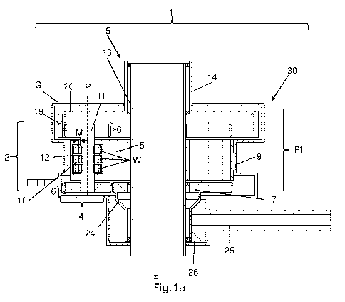
Fig. la shows a longitudinal section along A-A (cf. Fig. lb) through a
first preferred embodiment of the drive unit 1 according to the
invention with a multi-stage, here two-stage, planetary gear
mechanism PI, for example for driving a main rotor, which is not shown
here, of a rotary wing aircraft (see Fig. 3 in particular in this regard).
The drive unit 1 according to the invention, which is here configured as
a two-stage planetary gear mechanism PI, comprises a central sun
wheel 17 and a plurality of planetary gears 4 bearing against an outer
toothing of the sun wheel 17, which is not shown here. The sun wheel
17 is surrounded by the bearing planetary gears 4, wherein the
planetary gears 4 are arranged concentrically to the sun wheel 17 and
a central axis z inside the planetary gear mechanism Pl. A planetary
gear 4 here comprises a lower planet wheel 6, an upper planet wheel
6' and an inner rotor part 11 connecting the planet gears 6; 6' in a
rotationally fixed manner to form two stages of the here two-stage
planetary gear mechanism PI, and a stator part 12.
The first preferred embodiment shown here has a shaft 15, which is
configured to be two-part and comprises a bearing mast 13 and an
outer mast 14. The main rotor of a rotary wing aircraft or a marine
propeller or the like for example can be driven by means of the outer
mast 14 or the shaft 15. The drive unit 1 according to the invention,
which drives the shaft 15, can be applied in a very wide range of
technical fields. In other words, the gear mechanism or planetary gear
mechanism PI of the drive unit according to the invention can also be
understood as a torque transmitter gear mechanism 30.
At height or in the same axial position of the upper planet wheels 6',
an annular gear 19 is arranged rotatably about the central axis z. The
annular gear 19 surrounds all upper planet wheels 6', can be driven by
the rotation of the upper planet wheels 6' and can therefore be rotated
14/34
Date Recue/Date Received 2021-08-02
CA 03128856 2021-08-02
MMS-024-P-WO
about the central axis z. An inner toothing, which is not shown here, is
arranged on the annular gear 19, which is in engagement with an
outer toothing (not shown here) of the upper planet wheels 6' (when
realized in two-stage form, as shown here in Fig. la).
A mechanical operative connection between the upper planet wheels 6'
and an outer mast 14, which can be rotated about the central axis z, is
present for driving this outer mast 14 of the shaft 15. In the present,
first preferred embodiment, this mechanical operative connection is
realized on the basis of an annular-gear driver 20, which is connected
to the outer mast 14 in a rotationally fixed manner. In other words,
the annular-gear driver 20, which is likewise arranged on the annular
gear 19, here functions as a force transmission unit, by means of
which the rotation of the annular gear 19 can be transmitted to the
rotatable outer mast 14.
As can be seen in Fig. la, a first electric drive 2, here in particular an
electric synchronous motor 10 with inner rotor part 11, is integrated
into at least one planetary gear 4 to form a first drive unit 1, so that
the shaft 15 can be set rotating by the first drive 2. A stator part 12,
which functions as stator of the synchronous motor 10, is substantially
annular here and is provided with windings W, is here accommodated
in the planet wheel carrier 5 and securely connected to the planet
wheel carrier 5. The pin-shaped inner rotor part 11, which functions as
rotor of the synchronous motor 10, is connected in a rotationally fixed
manner to the upper and lower planet wheels 6; 6'. The planetary gear
4 is operatively connected to the sun wheel 17 and the rotatable shaft
15 inside the planetary gear mechanism PI and held here in a fixed
position by means of planet wheel carriers 5.
In the electric synchronous motor 10 shown in Fig. la, the force action
of the synchronous motor 10 is created in the air gap or magnetic gap
M between stator part 12 (stator) and inner rotor part 11 (rotor).
15/34
Date Recue/Date Received 2021-08-02
CA 03128856 2021-08-02
MMS-024-P-WO
As can be seen in Fig. la, a sun wheel 17 constructed as a hollow shaft
is connected to a drive gear 24, wherein the sun wheel 17 has an outer
toothing which is not shown here. The sun wheel 17 and the drive gear
24 are attached to the bearing mast 13 rotatably about the central axis
z. A rotation of the planet wheel 6' about a respective planet wheel
axis P can be achieved by means of the sun wheel 17 via the lower
planet wheel 6.
The drive gear 24 is in turn in operative connection with at least one
drivetrain 25 by means of a drivetrain gear 26. Here, the drivetrain 25
is preferably in mechanical operative connection with a further drive
TK, which is not shown here and is configured as a thermodynamic
engine, to form a hybrid drive or a hybrid variant comprising the drive
unit 1 according to the invention.
In the following, the use of the hybrid variant according to the first
preferred embodiment of a drive unit 1 to drive the main rotor of a
rotary wing aircraft is described by way of example (wherein the
second to fifth preferred embodiments are equally suited to driving the
main rotor of a rotary wing aircraft):
In this case, the torque transmitter gear mechanism 30 of the drive
unit 1 according to the invention can here be understood as a main
rotor gear mechanism or helicopter rotor gear mechanism of a rotary
wing aircraft, which is configured as a planetary gear mechanism PI
here.
The shaft 15 or rotor shaft here is configured to be two-part,
comprising a bearing mast 13 and an outer mast 14.
The helicopter rotor gear mechanism has a central cavity. The here
positionally fixed and rotationally fixed bearing mast 13 is mounted in
16/34
Date Recue/Date Received 2021-08-02
CA 03128856 2021-08-02
MMS-024-P-WO
this central cavity. The central axis z at the same time forms the
longitudinal direction of the bearing mast 13 and an axis of rotation of
the outer mast 14.
A mechanical operative connection between the here fixed planet
wheels 6; 6', which are mounted rotatably about their planet wheel
axis P, and a shaft 15 that can be rotated about the central axis z, i.e.
comprising here a bearing mast 13 and a tubular outer mast 14
surrounding the bearing mast 13, is realized in that the positionally
fixed upper planet wheels 6' are surrounded by an annular gear 19,
which is rotatable about the central axis z and is internally toothed,
and the annular gear 19 can be rotated in such a manner that the
outer mast 14 of the shaft 15 can be set rotating by means of an
annular-gear driver 20 fastened to the annular gear 19 and to the
outer mast 14.
As can be seen in Fig. la, a first electric drive 2, here in particular an
electric synchronous motor 10 with inner rotor part 11, is integrated
into at least one planetary gear 4 to form a first drive unit 1, so that
the outer mast 14 of the shaft 15 can be set rotating by the first drive
2. A stator part 12, which functions as the stator of the synchronous
motor 10, is here accommodated in the planet wheel carrier 5 and
securely connected to the planetary carrier, whilst the pin-shaped
inner rotor part 11, which functions as rotor of the synchronous motor
10, is connected in a rotationally fixed manner to the upper and lower
planet wheels 6; 6'.
The first preferred embodiment of the drive unit 1 according to the
invention, which is shown in Figs la to ld and is suitable for a rotary
wing aircraft or helicopter, in particular has safety advantages in the
context of this use. In an emergency, in the form of a failure of a drive
of such a multi-engined helicopter, the helicopter should be able to
rely for a predetermined period on the power from the further
17/34
Date Recue/Date Received 2021-08-02
CA 03128856 2021-08-02
MMS-024-P-WO
remaining engine, in order to set the helicopter in a safe flight regime
and to react to the engine failure.
The first preferred embodiment of the drivetrain 25 shown in Fig. la is
preferably also in mechanical operative connection with a further drive
TK, which is not shown here and is configured as a thermodynamic
engine, to form a hybrid drive. In this case, in addition to a second
drive TK configured as a thermodynamic engine, additional mechanical
work can be performed by a first, here electric, drive 2 and an
associated electrical energy source. Such helicopters with a hybrid
drive advantageously offer an additional safety advantage compared to
twin-engined helicopters solely with fossil fuel supply, as for example
in the event of the failure of the fossil fuel supply, recourse can be had
to the additional electrical energy supply.
Due to the integration of the first drive 2, particularly the electric
synchronous motor, into the planetary gears 4, a distinctly compact
hybrid drive is achieved in a twin-engined helicopter (for example in
the sense of a dissimilar helicopter).
As can be seen in Fig. la, here, the bearing mast is configured as a
hollow body, so that components such as control rods for attaching a
swash plate and/or cabling arranged above the rotor-blade coupling
device can be arranged traversing the bearing mast 13 and the outer
mast 14 in the direction of the central axis z. For example, the
electrical supply lines for electrical power supply to the rotating
system, such as anti-icing devices for the rotor blades, lamps in the
rotor blades or electrical actuators for a 'fly-by-wire' system may also
be arranged here.
From here and in the following, the same reference numerals
designate the same components in the figures.
18/34
Date Recue/Date Received 2021-08-02
CA 03128856 2021-08-02
MMS-024-P-WO
Fig. lb shows a plan view of the first preferred embodiment of the
drive unit 1 according to the invention with attached gear mechanism
housing G.
Fig. lc shows a perspective view of the first preferred embodiment of
the drive unit 1 according to the invention without or with removed
housing. By way of example, the first preferred embodiment shown in
Fig. lc has four planetary gears 4.
Fig. id shows a perspective view of the first preferred embodiment of
the drive unit 1 according to the invention with a housing G. In this
case, the drive unit 1 comprises a control unit ST, which is configured
so as to synchronize the first drives 2 integrated in the planetary gears
4 with one another. This synchronization of the first drives 2 integrated
in the planetary gears 4 is explained more precisely in Fig. 6.
Furthermore, these drives 2 integrated in the planetary gears may be
configured such that they can be decoupled from one another
mechanically, electrically or hydraulically by means of a suitable
coupling, which is not shown here, in order to prevent a possible
jamming of the gear mechanism due to a malfunction of one or more
drives.
Furthermore, here according to Fig. ld, the drive unit 1 comprises an
electrical energy source, particularly a battery storage unit BS shown
here, and wherein the first drive 2 in the form of a, here electric, drive
of the hybrid drive [lacuna] in a rotationally fixed coupled state
between the first, here electric, drive 2 and the second drive TK, which
is configured as a thermodynamic engine. During the operation of the
second drive TK, the first, here electric, drive 2 can function as a
generator and take care of an additional energy recovery for the
battery storage unit BS.
19/34
Date Recue/Date Received 2021-08-02
CA 03128856 2021-08-02
MMS-024-P-WO
A rectifier, particularly in the form of a blocking diode, is preferably
provided in the first, in particular electric, drive 2, particularly the
electric synchronous motor with inner rotor part 11, as a result of
which the battery storage unit BS can be charged when the electric
drive is not operating.
In addition, the control unit ST can furthermore be provided with a
logic which enables an automatic change of mode between torque
generation for driving the main rotor and the additional energy
recovery for the battery storage unit BS.
The first preferred embodiment, which is shown in Figs la to ld, in
other words shows a hybrid variant comprising the drive unit 1
according to the invention. Owing to the design as a two-stage
planetary gear mechanism PI, an optimum higher transmission can be
set up, whilst at the same time, the advantages of a hybrid drive (for
example safety advantages when used in a rotary wing aircraft) are
achieved.
According to a preferred development of the present invention, the
planetary gear mechanism can also be configured as more than two-
stage, e.g. three-stage, etc.
Fig. 2a shows a longitudinal section along A-A (cf. Fig. 2b) through a
second preferred embodiment of the drive unit 1 according to the
invention with a two-stage planetary gear mechanism PI as a hybrid
variant with an inner externally toothed annular gear 18.
The drive unit 1 according to the invention, which is here configured as
a two-stage planetary gear mechanism PI, comprises a central sun
wheel 17 and a plurality of planetary gears 4 surrounding the sun
wheel 17, bearing against an outer toothing of the sun wheel 17, which
is not shown here, wherein planetary gears 4 are arranged
20/34
Date Recue/Date Received 2021-08-02
CA 03128856 2021-08-02
MMS-024-P-WO
concentrically to the sun wheel 17 and a central axis z inside the
planetary gear mechanism Pl.
As shown in Fig. 2a, an internal, externally toothed annular gear 18,
which is connected in a rotationally fixed manner to the outer mast 14,
is here surrounded by the upper planet wheels 6' and can likewise be
driven by the rotation of the upper planet wheels 6', thus can be
rotated about the central axis z and can be set rotating together with
the outer mast 14. An outer toothing, which is not shown here, is
arranged on the annular gear 18, which is in engagement with an
outer toothing (not shown here) of the upper planet wheels 6'.
Fig. 2b shows a plan view of the second preferred embodiment of the
drive unit 1 according to the invention with attached gear mechanism
housing G.
Fig. 2c shows a perspective view of the second preferred embodiment
of the drive unit according to the invention without a gear mechanism
housing.
Fig. 2d shows a perspective view of the second preferred embodiment
of the drive unit according to the invention with a gear mechanism
housing G.
Fig. 3a shows a longitudinal section along A-A (cf. Fig. 3b) through a
third preferred embodiment of the drive unit 1 according to the
invention with a one-stage planetary gear mechanism PI, for example
for driving a main rotor, which is not shown here, of a rotary wing
aircraft.
As can be seen in Fig. 3a, in the third preferred embodiment shown
here, it is possible to dispense with a sun wheel (as also in the fourth
preferred embodiments shown in Figs 4a to 4d or in the fifth preferred
21/34
Date Recue/Date Received 2021-08-02
CA 03128856 2021-08-02
MMS-024-P-WO
embodiments shown in Figs 5a to 5d), which therefore corresponds to
a gear mechanism related to a planetary gear mechanism Pl. This
possible dispensation with a sun wheel has the advantage of a weight
reduction and a reduction of the complexity.
The use of such a one-stage planetary gear mechanism PI has the
advantage that in the third preferred embodiment shown here, no
external gear mechanism housing G extending over two stages has to
be attached, and as a result, the first drive 2 integrated in the
planetary gears 4, here configured as an electric synchronous motor
10 with inner rotor part 11, can be cooled better. In particular, up to a
certain power value, the heat losses will be small enough to avoid a
liquid cooling circuit, and therefore as a result, no liquid cooling is
necessary, i.e. the available air cooling by means of the ambient air
around the planetary gears 4 already effects a satisfactory cooling. In
addition, it has been shown that in the case of a modular structure of
the electric drive over a plurality of stages with low electrical power,
the power values without required liquid cooling is higher than in the
case of a single, electric drive.
Fig. 3b shows a plan view of the third preferred embodiment of the
drive unit according to the invention with attached gear mechanism
housing G.
Fig. 3c shows a perspective view of the third preferred embodiment of
the drive unit 1 according to the invention without or with removed
housing. The third preferred embodiment shown here has six planetary
gears 4 by way of example.
Fig. 3d shows a perspective view of the third preferred embodiment of
the drive unit 1 according to the invention with gear mechanism
housing G.
22/34
Date Recue/Date Received 2021-08-02
CA 03128856 2021-08-02
MMS-024-P-WO
Figs 3a to 3d relating to the third preferred embodiment with a one-
stage planetary gear mechanism PI show a fully electric variant of the
drive unit 1 according to the invention, wherein a hybrid variant
comprising a drive unit 1 configured as a one-stage planetary gear
mechanism PI is likewise possible. A one-stage planetary gear
mechanism PI is understood to mean that the planetary gears 4 only
comprise one upper planet wheel 6' and therefore only have one stage.
Fundamentally, an even simpler embodiment of the drive according to
the invention is additionally conceivable, wherein the torque can be
transmitted by an externally toothed annular gear 18 instead of by
means of an internally toothed annular gear 19 (cf. Figs 2a to 2d or
Figs 4a to 4d).
Fig. 4a shows a longitudinal section through a fourth preferred
embodiment of the drive unit 1 according to the invention with a one-
stage planetary gear mechanism constructed as a fully electric drive
variant and with an inner, externally toothed annular gear, particularly
for driving the main rotor of a rotary wing aircraft.
As shown in Fig. 4a, an internal, externally toothed annular gear 18,
which is connected in a rotationally fixed manner to the outer mast 14,
is here surrounded by the upper planet wheels 6' and can likewise be
driven by the rotation of the upper planet wheels 6' and together with
the outer mast 14 about the central axis z.
Fig. 4b shows a plan view of the fourth preferred embodiment of the
drive unit according to the invention with attached gear mechanism
housing G.
Fig. 4c shows a perspective view of the fourth preferred embodiment
of the drive unit according to the invention without a gear mechanism
housing.
23/34
Date Recue/Date Received 2021-08-02
CA 03128856 2021-08-02
MMS-024-P-WO
Fig. 4d shows a perspective view of the fourth preferred embodiment
of the drive unit according to the invention with a gear mechanism
housing G.
Fig. Sa shows a longitudinal section along A-A (cf. Fig. 5b) through a
fifth preferred embodiment of the drive unit 1 according to the
invention with a one-stage planetary gear mechanism PI as a fully
electric drive variant and as an outer rotor variant.
As can be seen in Fig. 5a, a first, here electric, drive 2, here in
particular an electric synchronous motor 10 with outer rotor part 16, is
integrated into at least one planetary gear 4 to form a first drive unit
1.
A stationary stator part 12, which functions as stator of the
synchronous motor 10, is substantially annular here and is provided
with windings W, is here accommodated in a pin-shaped element S
and securely connected to the pin-shaped element S, whilst the outer
rotor part 16 of the synchronous motor, which here functions as a
rotor of the synchronous motor 10, is here connected to the planet
wheel 6 in a rotationally fixed manner. The planet wheel 6 and the
outer rotor part 16 of the electric synchronous motor 10 here lie in the
same plane or in the same axial position and essentially form one unit.
As can be seen in Fig. 5a, here, on one side, the positionally fixed
planet wheels 6' of the planetary gears 4 are surrounded by an
internally toothed annular gear 19 that can be rotated about the
central axis z and on the other side, an inner externally toothed
annular gear 18 is surrounded by the planet wheels 6', wherein an
outer mast 14, which is not shown here, can be set rotating by means
of the internally toothed annular gear 19 (cf. Fig. 5b) and a further
central drive shaft, which is not shown here, can be set rotating by
24/34
Date Recue/Date Received 2021-08-02
CA 03128856 2021-08-02
MMS-024-P-WO
means of the inner externally toothed annular gear 18 (cf. Fig. 5b). In
other words, on the basis of the fifth preferred embodiment, two shafts
can be set rotating with different transmission. In addition, it is
indicated in Fig. 5a, that in the case of a here likewise possible
configuration of a hybrid variant, the externally toothed annular gear
18 can function as sun wheel 17.
Fig. 513 shows a plan view of the fifth preferred embodiment of the
drive unit 1 according to the invention with attached gear mechanism
housing G and in operative connection with an outer mast 14 or a
central drive shaft 27. As can be seen in Fig. 5b, the internally toothed
annular gear 19 may be in operative connection with the outer mast
14 or the shaft 15 via a multiplicity of connecting elements V.
Alternatively or additionally, the externally toothed annular gear 18 or
the sun wheel 17 may, in particular as a configuration of a hybrid
variant, be in operative connection with a central drive shaft 27 via a
multiplicity of connecting elements V.
Furthermore, it is indicated in Fig. 5b that in the case of the
configuration as non hybrid variant or fully electric drive variant in the
sense of a further preferred development, the inner externally toothed
annular gear 18 may be in operative connection with the outer mast.
Fig. Sc shows a perspective view of the fifth preferred embodiment of
the drive unit 1 according to the invention without gear mechanism
housing, central drive shaft and outer mast. As can be seen in Fig. Sc,
the planet wheel carrier 5 is here connected in a rotationally fixed and
positionally fixed manner to a base element B functioning as bearing
mast 13 via the carrier arms 9. In addition, the bearing mast 13 here
comprises a pipe element R, which is arranged centrally and coaxially
to the central axis z, for a further shaft, which is fastened on the
annular gear 18.
25/34
Date Recue/Date Received 2021-08-02
CA 03128856 2021-08-02
MMS-024-P-WO
In addition, it can be seen in Fig. 5c that here the planet wheel carrier
is configured as a single coherent substantially annular component,
in which the planetary gears 4 are held in a positionally fixed manner.
5 Fig. Sd shows a perspective view of the fifth preferred embodiment of
the drive unit 1 according to the invention with gear mechanism
housing G, but without central drive shaft and without outer mast. As
can be seen in Fig. 5d, the carrier arms 9 are at the same time used
for fastening the gear mechanism housing G.
The fifth preferred embodiment of the drive unit 1 according to the
invention shown in Figs 5a to 5d has a particularly compact design, in
which the attachable rotating outer mast 14 can be configured in such
a shortened manner on the externally toothed annular gear 18 or on
the internally toothed annular gear 19, that the same can be attached
essentially at the same axial position as the planetary gears 4. In the
case of the use for a rotary wing aircraft, the drive unit 1 would be
attachable fundamentally directly in the rotor plane.
Fig. 6 shows a functional block diagram of the drive power control of
the first drives 2 integrated in the planetary gears P.
As can be seen by way of example in Figs ld, 2d, 3d, 4d and 5d, the
drive unit 1 comprises a control unit ST, which is configured so as to
operate and to synchronize the first drives 2 integrated in the
planetary gears 4 with one another.
In the sense of the present invention, the control is realized as a
standard control for electric synchronous motors 10 with control logic
and power electronics unit LEE (also termed "inverter" here). The
control logic (also termed "motor controller" here) produces the
corresponding signals which control the inverter, which then excites
the corresponding motor coils of the electric synchronous motor 10, in
26/34
Date Recue/Date Received 2021-08-02
CA 03128856 2021-08-02
MMS-024-P-WO
order to obtain a continuous rotation with defined rotational speed and
torque. The synchronization of the electric synchronous motors 10 is
enabled by determining the position and the rotational speed of the
armature and for each electric synchronous motor 10 individually by
calculating the control signals.
27/34
Date Recue/Date Received 2021-08-02
CA 03128856 2021-08-02
MMS-024-P-WO
Reference list
1 Drive unit
2 First drive
4 Planetary gear
5 Planet wheel carrier
6; 6' Lower/upper planet wheel
7 Electrical supply lines
9 Carrier arms (for fastening the planet wheel carrier 5 on the
gear
mechanism housing G)
10 Electric synchronous motor
11 Inner rotor part (of the electric synchronous motor)
12 Stator part
13 Bearing mast
14 Outer mast
15 Shaft
16 Outer rotor part (of the electric synchronous motor)
17 Sun wheel
18 (Inner, externally toothed) annular gear
19 (Outer, internally toothed) annular gear
20 Annular-gear driver
24 Central drive gear
Drivetrain
26 Drivetrain gear
27 Central drive shaft
25 30 Torque transmitter gear mechanism
B Base element
BS Battery storage unit
G Gear mechanism housing
M Magnetic gap
P Planet wheel axis
PI Planetary gear mechanism
R Tube element
S Pin-shaped element
ST Control unit
TK Second drive configured as a thermodynamic engine
V Connecting elements
W Windings (of the stator part)
28/34
Date Recue/Date Received 2021-08-02