Note : Les descriptions sont présentées dans la langue officielle dans laquelle elles ont été soumises.
1
MEDICAL DEVICE FOR BLOOD VESSEL COMPRESSION
TECHNICAL FIELD
Present disclosure relates to a medical device for blood vessels compression
that is applied
to a limb of a patient in order to achieve local haemostasis. In particular,
the device of the
disclosure is used in invasive cardiology and radiology to compress a blood
vessel upon removal
of a vascular sheath from a patient's blood vessel after heart
catheterization, coronary angiography
or other intravascular procedures and interventions that require a vascular
access port.
PRIOR ART
Many different blood vessel compression devices are known in the prior art.
For example,
W02013060883 discloses an arterial compression band having a tube-like shaped
body with
bevelled endings and a holding element in a form of a strap that is attached
to the outside surface
of the body. This medical device is applied at a bleeding vessel site, in
particular, the bleeding
site of an artery (radial or ulnar) from which a catheter or cannula has been
removed, by pressing
manually the body against the bleeding vessel site, followed by immobilizing
the body on the
patient's limb by applying the holding element around the patient's limb. The
device is fixed to
the patient's limb by the fastening means, such as a hook and loop fastener,
which can be located
on the holding element. The device disclosed therein is quite simple in
manufacturing and for
application to a patient's limb. Most of all, it provides manual control of
the blood vessel
compression upon placing the device on a patient's limb, i.e. a medical
personnel (for example a
physician or a nurse) can apply the body to the site of the catheter or
cannula entry to the blood
vessel, while gripping on the inside of the hollow body, remove the catheter
or cannula and, at the
same time, exert the necessary compression to the blood vessel, and fix the
body to the patient's
limb by applying the strap around the patient's limb and over the body of the
device while still
holding the inside of the hollow body.
However, once applied on a patient's limb the device is prone to accidental
displacement,
either by tipping over or by shifting or sliding. This influences the
compression force exerted on
blood vessel or even the compression application site on the limb after the
device was applied,
making the device less effective at its primary purpose. Moreover, after the
device is fixed to the
patient's limb, the device does not provide a sufficient control of the
Date Recue/Date Received 2023-03-16
CA 03130410 2021-08-16
WO 2020/169573 2
PCT/EP2020/054189
compression level, especially when the compression needs to be gradually
decreased after the
device is placed on the patient. The compression is controlled only by strap
positioning or by
the means of adjusting the cross-section dimensions or shape of the body.
However, in the
first case the adjustment of the strap is required, which is very inconvenient
and requires the
medical staff to unfasten the holding means and fasten it again in a new
position, risking
device displacement that may result in bleeding. In the latter case, the
construction of the
body becomes very complex and the level of compression adjustment is also very
limited.
In order to ensure sufficient compression control in compression haemostatic
devices,
screw-and-nut systems can be used to exert pressure onto a patient's limb. In
/0
US20100280541, a radial artery compression device is disclosed that includes a
rotatable
member and a compression pad adapted in such a way that rotation of the
rotatable member
does not affect the rotational orientation of the compression pad. The
rotation of the rotatable
member results in extension or retraction of the compression pad relative to
the body of the
radial artery compression device, thus increasing or decreasing, respectively,
the compression
on a patient's radial artery. Therefore, in such devices the screw-and-nut
system drives the
compression pad directly, thus enabling precise compression control. A similar
device is
described in US20120191127. However, in this case the screw-and-nut system can
also be
located outside the diameter of the compression pad, which is attached to the
base of the
device. In this case, the compression level is controlled by deflection of the
entire base.
Although, the above-described devices provide more precise control of the
compression level, they are not very easy to apply. They do not provide the
manual control
upon application as the device described in W02013060883. Even though the
rotatable
member is provided with a recess that can receive a finger or a thumb of a
medical personnel,
who controls the pressure of the device upon placing the device of a patient's
limb, this recess
is not very convenient for gripping, as it can only be accessed from the top
of the rotatable
member. Moreover, although said recess is provided with a transparent floor,
the view of the
catheter or cannula entry site is still significantly blocked by the screw-and-
nut system
elements. Finally, in both devices of US20100280541 and US20120191127 the
holding
means or base is in direct contact with the radial side of the patient's
forearm. Such a design
not only provides discomfort to a patient when the device is applied, but also
affects the blood
flow in neighbouring blood vessels, in particular arm veins or the ulnar
artery, because some
compression is unintentionally applied through the body and the straps.
Devices for the
compression of a selected blood vessel, for example, a more accurate
compression in which a
CA 03130410 2021-08-16
WO 2020/169573
PCT/EP2020/054189
3
radial artery is compressed while maintaining the blood flow in the
neighbouring blood
vessels would be useful but is not apparent from the prior art.
It is asserted that there remains a need for a device which can be securely
fixed in
position on a limb and which provides specific and accurate blood vessel
compression.
Moreover, it would be advantageous if the device is able to precisely control
that compression
without compromising on the simplicity of its construction or ergonomic
design.
SUMMARY OF THE INVENTION
The invention provides a vessel compression device for a limb, which
comprises:
/0 - a hollow body having an internal substantially annular surface and a
longitudinal base
defining and accessible by a generally tubular space;
- a compression area located at an external surface of the base;
- a compression control mechanism for regulating compression applied by the
device, wherein
the mechanism is located on the body distal to and opposite the compression
area and the
base;
- a strap for securing the device to the limb and effecting compression
thereon, the strap being
attached to body at the base and releasably attachable with and adjustable by
the compression
control mechanism without blocking the tubular space;
- a support for stabilising the device, the support being located adjacent
the base and
extending in a longitudinal direction parallel therewith.
When applied to an injured vessel, embodiments of the medical device disclosed
herein
provide blood vessel compression, in particular radial compression, for the
purpose of
establishing haemostasis. The blood vessel compression device of the invention
is
ergonomically designed, so that it is easily attached to the patient limb and
very convenient to
use by a medical personnel. When the device of the invention is applied to the
patient's limb
it is stable (i.e. it is not prone to sliding or tipping) and provides a
sufficient compression
control. The device of the invention also provides a greater comfort to a
patient, as the
compression on the radial side of a patient's forearm is essentially limited
to the catheter or
cannula blood vessel entry site. The design of the device of the invention
also prevents
compression of the blood vessels other than the blood vessel with the vascular
access port.
The device of the invention is constructed in such a way that its elements are
easy to
manufacture by plastic injection moulding. While designing the device, the
inventors took
under consideration the shape of injection moulds, to ensure that they have a
simple
CA 03130410 2021-08-16
WO 2020/169573 4
PCT/EP2020/054189
construction and that the elements produced by injection moulding could be
easily retrieved
from moulds.
In a preferred embodiment, the compression control mechanism of the device of
the
invention is based on a screw-and-nut system. Also preferably the strap,
which, in
embodiments, is attached to a hollow body at the vicinity of the compression
area (i.e. on the
opposite side of the hollow body relative to the compression control
mechanism), upon
application of the device on the patient's limb is guided across and over the
compression
control mechanism, which regulates the compression of the device by adjusting
the tension of
the strap.
/0
Also in this embodiment the hollow body has a cylindrical-like shape with
bevelled
endings. More preferably, the tubular space inside the hollow body is formed
by a through-
hole. In this embodiment, i.e. whenever the tubular space inside the hollow
body can be
accessed from both sides, the vessel compression device according to the
invention can be
used on both forearms of the patient and to compress different vessels.
In embodiments of the invention, the compression control mechanism comprises a
knob
and a tightener, wherein the knob is fitted over an externally-threaded
element of the hollow
body, which is located on the opposite side of the hollow body, relative to
the compression
area, and supports the tightener. When the device of the invention is attached
to the patient's
limb and the knob is turned, it moves along the externally-threaded element of
the hollow
body and changes the vertical position of the tightener. As the tightener is
moved in the
vertical position, it does not turn around horizontally, providing a support
for the strap. As the
knob and the tightener move away from the middle of the hollow body (i.e. away
from the
compression area), the tightener presses upon the strap and increases its
tension, thus
increasing the compression of the device against patient's limb. When the knob
is turned in
the opposite direction, it moves along the externally-threaded element of the
hollow body
towards the middle of the hollow body (i.e. towards the compression area). The
tightener
follows the movement of the knob, thus decreasing the tension of the strap and
the
compression of the hollow body against the patient's limb.
The compression control mechanism, which adjusts the tension of the strap,
allows for
precise control of the compression of the device against the patient's limb.
Also, due to the
fact that the strap is guided around the hollow body, it does not compress the
radial side of the
patients forearm, thus eliminating the compression of other blood vessels,
and, at the same
time it does not block the access to the tubular space of the hollow body,
thus allowing a
comfortable grip of the device of the invention by pressing the compression
area of the hollow
CA 03130410 2021-08-16
WO 2020/169573
PCT/EP2020/054189
body with a finger or a thumb of a medical personnel received in said tubular
space of the
hollow body. The hollow body, the compression control mechanism and the strap,
are
preferably made of transparent material and do not block the view of the blood
vessel
compression area. This enables visual control of the catheter or cannula
vessel entry site upon
5 or after removal thereof. Therefore, it is possible to determine if the
haemostasis is achieved
or to detect the bleeding from the injured vessel.
In one preferred embodiment, the stabilizing support protrudes from the hollow
body in
the proximity of its compression area. Additionally, in the preferred
embodiment, the support
for stabilizing the body is in a form of a bent fin, whose edge opposite to
the edge attached to
the hollow body is in the same plane as the compression area of the hollow
body, thus
providing the support for the hollow body, whereas the remaining part of the
support is raised
above the plane of the compression area. Such a shape of the stabilizing
support minimalizes
the contact of the device of the invention with the patient's limb, thus
increasing the patient's
comfort and decreasing the compression of the device on the area of the
patient's limb other
than the site of the punctured blood vessel. That way the compression of blood
vessels other
than that providing the vascular access point is minimalized. The device of
the invention is
therefore designed to provide precise compression control onto a selected
blood vessel, while
maintaining the blood flow in neighbouring blood vessels unaffected.
If the device is used to compress the radial artery, the ulnar artery is not
compressed as
.. the stabilizing support is raised above the surface of the patient's
forearm region, which
corresponds to the position of the ulnar artery. Accordingly, if the device is
used to compress
the ulnar artery (i.e. it is applied to the limb in the opposite direction),
the radial artery is not
compressed. Most of all, due to the device design, in particular the design of
the stabilizing
support, whose contact with the patient's limb is limited, the device does not
compress the
neighbouring veins. Therefore, the venous outflow from the hand is not
hindered by the
compression of the device on patient's limb and venostasis is avoided. This
not only increases
patient comfort, but also reduces the risk of side effects associated with
catheterization and
compression of the limb.
Even though only the edge of the stabilizing support opposite to the edge
connected to
the hollow body is in contact with the patient's forearm, the desired
stability to the entire
device of the invention is provided. The stabilizing support prevents the
displacement of the
device of the invention by tipping over or sliding, while it is attached to
the patient's limb. In
the most preferred embodiment, the stabilizing support is in a form of a bent
fin having a
wave-type cross section, wherein the edge of the support opposite to the edge
connected to the
6
hollow body is provided with a supporting foot. This supporting foot increases
the patient's
comfort, when the device of the invention is attached to the patient's limb.
In the preferred embodiment the strap of the device of the invention is made
of anti-skid
material. Preferably, the strap is made of a material that requires no
additional fastening means to
hold the device of the invention of the patient's limb. In particular, one
surface of the straps ¨ the
outer surface, adheres to the opposite surface of the strap ¨ the inner
surface, when the strap is
secured around the patient's limb and the outer and inner surface of the strap
come in contact. In
an alternative embodiment, the strap can be provided with additional fastening
means for holding
the device in a desirable position on the patient's limb selected from a group
comprising an
adhesive (for example, in a form of a locking sticker), tightening buckles,
hooks, snap fasteners
(for examples, orifices and the corresponding lugs) or hook and loop
fasteners, such as Velcro".
In some preferred embodiments the fastening means comprises two parts situated
on the opposite
surfaces of the strap, which come into contact when the device of the
invention is attached to the
patient's limb. In the preferred embodiment the fastening means are provided
at the free end of
the strap, i.e. the end of the strap opposite to the strap end connected to
the base of the hollow
body.
In embodiments, the device of the invention is equipped with a clicking
mechanism, which
indicates the turn of the knob on the externally-threaded element. That way an
acoustic control of
the compression adjustment is possible. The clicking mechanism according to
the preferred
embodiment comprises a ring spring, which is fixed within the tightener,
wherein said ring spring
comprises downward protrusions that engage with uniformly spaced cogs located
in the vicinity
of the knob rim closest to the tightener. That way, whenever the knob is
turned the protrusion of
the ring spring is displaced from one space between the cogs to another,
wherein upon the
displacement it engages with the cog and produces a clicking sound. The system
consisting of the
ring spring with protrusions that engage with the elements on the knob is very
space efficient.
Therefore, the clicking functionality of the device of the invention can be
introduced without
increasing the size of the entire device of the invention. Moreover, the
design of the clicking
mechanism renders its manufacturing method quite simple, since it does not
require any complex
injection moulding forms.
Date Recue/Date Received 2023-03-16
6a
In one embodiment, there is provided a blood vessel compression device for a
limb. The
device comprises: a hollow body having an internal substantially annular
surface and a base
defining a generally tubular space extending in a longitudinal direction, said
base being accessible
by the generally tubular space; a compression area located at an external
surface of the base; and
.. a compression control mechanism for regulating compression applied by the
device. The device
further comprises a strap for securing the device to the limb and effecting
compression thereon.
The strap is attached to the hollow body at the base and releasably attachable
with and adjustable
by the compression control mechanism without blocking the generally tubular
space. The
compression control mechanism is located on the hollow body distal to and
opposite the
compression area and the base. The device further comprises a support for
stabilising the device.
The support is located adjacent the base and extending in a longitudinal
direction parallel
therewith.
BRIEF DESCRIPTION OF THE DRAWINGS
.. The present invention will be described in a greater detail herein below in
reference to a drawing
wherein:
Date Recue/Date Received 2023-03-16
CA 03130410 2021-08-16
WO 2020/169573
PCT/EP2020/054189
7
Fig. 1 a presents a perspective view of the vessel compression device
according to the
preferred embodiment of the present invention is shown in the folded form;
Fig. lb presents a side view of the device presented in Fig. la in an unfolded
form;
Fig. 2a presents an exploded view of the vessel compression device of the
invention from
Fig. la and lb;
Fig. 2b and 2c presents enlarged parts of the exploded view A and B,
respectively, from
Fig. 2a;
Fig. 3 presents the hollow body of the vessel compression device of the
invention in a
perspective view (Fig. 3a), in a front view (Fig. 3b), side views (Fig. 3c)
and bottom view
/0 (Fig. 3d);
Fig. 4 presents a tightener of the vessel compression device of the invention
in a perspective
view from the bottom (Fig. 4a), in a bottom view with a ring spring (Fig. 4b),
in a top view
(Fig. 4c) and in the side views (Fig. 4-d and Fig. 4e);
Fig. 5 presents a knob of the compression device of the invention in a
perspective view from
the bottom (Fig. 4a) and from the top (Fig. 5b), in a top view (Fig. Sc) and a
cross-section
along A-A line of the knob presented in Fig. Sc (Fig. 5d);
Fig. 6 presents a perspective and top views of the ring spring in the vessel
compression device
of the invention; and
Fig. 7 presents a bottom view of a strap of the vessel compression device of
the invention.
DETAILED DESCRIPTION
The present invention relates to a vessel compression device 1.
Whenever a reference is herein made to a term "bottom" or "below" or
"underneath"
with respect to the device 1 or an element thereof, it means a part of the
device 1 proximal to
the patient and limb desired to be compressed, when the device 1 is properly
attached to said
limb. The term "downwards" also means in a direction towards the patient's
limb.
The term "top" or "above" as used herein in reference to the device 1 or an
element
thereof, refers to the part of the device 1, which is located distal from the
patient's limb, when
the device 1 is properly attached to said limb. The term "upwards" refers to a
distal direction
from the patient's limb.
The device 1 of the invention has been designed to apply proper compression
forces in
the specific area of the limb in order to prevent bleeding from an injured
blood vessel. At the
same time, the device 1 does not apply forces to other major blood vessels in
a patient's limb.
CA 03130410 2021-08-16
WO 2020/169573 8
PCT/EP2020/054189
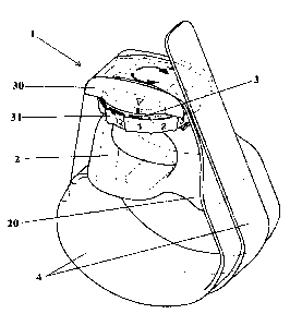
As presented in Figs. la and lb and Figs. 2a, 2b and 2c, the device 1
comprises four
main elements: a hollow body 2, a compression control mechanism 3 comprising a
tightener
30 and a knob 31, and a strap 4. The hollow body 2 forms a central element of
the device 1.
The strap 4 is securely attached to the hollow body 2, in particular to a base
26 of the hollow
body 2. This ensures that the strap 4 remains attached to the hollow body 2
during regular use,
when it is subjected to significant forces. In this embodiment the strap 4 is
attached to the
compression area 24 by means of an adhesive 5 and the contact area between the
strap 4 and
the hollow body 2 corresponds to the entire compression area 24 of the hollow
body 2. This
large contact area not only ensures that the strap 4 is well secured to the
hollow body 2, but
/0 also provides additional stability to the device 1 when the device is
attached to the patient's
limb, in particular prevents the device 1 from sliding sideways when the
device is applied or
when the compression forces are adjusted.
On the opposite side to the strap 4 attachment site, i.e. at the top, the
device 1 is
provided with a tightener 30 and a knob 31, both of which are in a bolt-nut
movable
connection with hollow body 2, in particular with the externally-threaded
element 21 of the
hollow body 2. The tightener 30 is supported by the knob 31, which is located
underneath of
the tightener 30. After the device 1 is assembled, the tightener 30 and the
knob 31 move
together relative to the hollow body 2 along the externally-threaded element
21 of the hollow
body 2. The movement of the tightener 30 relative the hollow body 2 provides
control of the
compression of the device 1 onto the patient's limb.
As shown in Figs. 3a-d the hollow body 2 is formed as an integral element. In
this
embodiment, the hollow body 2 is in a form of a short tube with a cross-
section of a flattened
circle. In particular, the base 26 of the hollow body 2 flattened to provide a
better contact with
the patient's limb. However, it can be formed in any other shape that will be
configured to
provide a medical personnel with a suitable access to the compression area 24
via the base 26
of the hollow body 2 (i.e. the tubular space 23 within the body 2, where the
medical personnel
can insert his or her finger in order to apply the force onto the bottom 26 of
the hollow body
2, so that upon application of the device 1 to the patient's limb the medical
personnel can
apply force to injured vessel manually). In embodiments, the hollow body 2 is
symmetrical
along its long axis, thus rendering the device of the invention operational on
both hands.
Moreover, the selected shape of the body 2 needs to accommodate the tightener
30 and the
knob 31 placed above the tubular space 23 within the hollow body 2. For
example, the body 2
can be in a shape of a half-pipe, whose walls are connected by an externally-
threaded element
21 that receives the tightener 30 and knob 31. In the presently described
preferred
CA 03130410 2021-08-16
WO 2020/169573 9
PCT/EP2020/054189
embodiment, the tube that forms the central part of the hollow body 2 has a
longitudinal base
26, which is directed towards a patient's limb, when the device 1 is applied
properly. The base
26 is connected with the externally-threaded element 11 by side walls 22. The
base 26 of the
tube is wider than the side walls 22 of the tube and has a larger surface area
than the side
walls 22. The outer surface of the base 26 of the hollow body 2 provides a
compression area
24, which is configured to be in contact with the patient's limb when the
device 1 is applied.
In the present embodiment, the compression area 24 is covered with an adhesive
5 that
connects the strap 4 to the compression area 24. Therefore, the compression
area 24 is in
contact with the patient's limb through the strap 4 and adhesive 5. Moreover,
the compression
/0 area 24 preferably comprises a mark 25 that facilitates the positioning
of the device 1 on
patent's limb. When applied to a patient's limb, the positioning mark 25
should be placed at
the site of the vascular access port. In the preferred embodiment the hollow
body 2 together
with its integral elements is formed of transparent plastic material. Use of
the transparent
material ensures a visual control of the catheter or cannula entry site on the
patient's limb. In
this embodiment, the body 2 is made of polycarbonate by injection moulding.
Additionally,
the edges of the hollow body 2 are blunt to increase the comfort of the
patient.
The hollow body 2, in embodiments, is provided with a support 20, which may be
an
integral part of the hollow body 2. The support 20 extends from a side of the
hollow body 2
(i.e. from the side wall 22 of the hollow body 2 near the base 26 of the
hollow body 2), and
away from the compression area 24.
In the preferred embodiment, the support 20 is in a form of a bent fin having
a wave-
type cross section. Initially, as it extends away from the hollow body 2, the
bent fin of the
support 20 is directed upwards to the inflection point where its direction
changes towards the
plane of the compression area 24. The support 20 does not extend beyond the
plane of the
base 26 of the hollow body 2. Moreover, at its free end (i.e. opposite to the
site where the
support 20 is connected to the side wall 22 of the hollow body 2), the support
20 is equipped
with a supporting foot 200. When the device is applied to the patient's limb,
the support 20 is
in contact with a patient's limb, at a certain distance from the compression
area 24. The
contact of the support 20 is provided only by its free end or by the foot 200
of the support 20
as presented in this embodiment. That way, the device 1 does not compress
other major blood
vessels, which are in the vicinity of the blood vessel undergoing the medical
procedure. Thus,
the distance between the compression area 24 and the supporting foot 200 of
the support 20
provides the space without compression that results in an undisturbed blood
flow in other
blood vessels that are not intended to be compressed in the medical procedure.
Therefore, the
CA 03130410 2021-08-16
WO 2020/169573 10
PCT/EP2020/054189
contact of the device 1 with the surface of the palm side of the patient's
foreami is limited to
the minimum, i.e. to the compression area 24 and the free end of the support
20 or the foot
200 if it is present at the free end of the support 20, thus decreasing the
discomfort level in a
patient when device 1 is applied.
Despite its limited contact to the patient's limb, the support 20 provides an
additional
support to the device 1. The function of support 20 is, therefore, to
stabilize the hollow body 2
on a patient's limb and consequently prevent any undesired movement of the
device 1 after it
is secured to the patient's limb. Without the support 20, the device would be
prone to tipping
sideways due to the forces that are applied by the strap 4. Preferably, the
support 20 has a
/0 wave-type shape, as shown in Fig. 3a and 3b. Other shapes of the support
20 are also
envisaged, however the wave-type shape is most effective and meets both the
medical and
aesthetic requirements. Additionally, the free end of the support 20 or the
supporting foot 200
is provided with an inset, preferably made of an elastic material, that is
applied to a surface of
the supporting foot 200 or to the surface of the support 20, which comes into
the direct
contact with the patient's limb. This also aims to increase the patient's
comfort when the
device 1 is applied.
In the presently described embodiment, the hollow body 2, which is in a form
of the
tube, includes the side walls 22, which extend from base 26 circumferentially
and are
connected at the top by the externally-threaded element 21. Inside of the
tube, between the
base 26, side walls 22 and externally-threaded element 21 (i.e. within a
periphery formed by
the side walls 22, base 26 and externally-threaded element 21), there is a
tubular space 23.
The tubular space 23 is designed to receive a finger or a thumb of a medical
personnel who,
upon application of the device onto the patient's limb, puts initial
compression onto the
compression area 24 by pressing the base 26 of the hollow body 2. In order to
provide a better
access to the base 26 of the hollow body 2, the width of the side walls 22
decreases as they
extend upwards (i.e. the walls gradually become narrower). The hollow body 2
is designed in
a manner that the tubular space 23 can be accessed from both sides of the
hollow body 2 (i.e.
the tube forming the hollow body 2 is opened on both endings). This way the
device is
suitable to be used on both left and right forearms of the patient. This
ensures a universal
character of the device.
The side walls 22 provide support for a top part of a hollow body 2 ¨ the
externally-
threaded element 21, which forms an integral part of the hollow body 2. In the
present
embodiment, the externally-threaded element 21 has a shape of a hollow screw
with the axis
of rotation positioned perpendicularly to an axis of the tube of the hollow
body 2. The axis of
CA 03130410 2021-08-16
WO 2020/169573 11
PCT/EP2020/054189
rotation of the externally-threaded element 21 is also perpendicular to the
surface of the base
26 of the hollow body 2. This threaded element 21 has a plurality of grooves
referred to as
guiding slots 27, which extend in parallel to the rotation axis of the
externally-threaded
element 21. In this embodiment, there are four guiding slots 27 located
symmetrically on the
externally-threaded element 21. The guiding slots 27 are situated along the
axis of rotation
and perpendicularly to the thread of the externally-threaded element 21. When
the device 1 is
assembled, the guiding slots 27 receive the knob supporting elements 301 and
guiding
elements 302 of the tightener 30. This way the hollow body 2 and the tightener
30 are
engaged with each other. Two of the guiding slots 27, which are located
opposite to each
/0 other and receive the guiding elements 302 of the tightener 30, are
provided at the top with
blocking protrusions 270. As the tightener 30 moves upwards, these blocking
protrusions 270
engage with free ends of the guiding elements 302 of the tightener 30, thus
blocking their
further upward movement and preventing the tightener 30 from becoming
disengaged from
the hollow body 2. The other pair of guiding slots 27, which are also located
opposite each
other, receives knob supporting elements 301 of the tightener 30.
The hollow body 2 in the assembled form of the device 1 engages with the
tightener 30,
which is placed above the hollow body 2. Fig. 4 presents a preferred
embodiment of the
tightener 30 of the device of the invention. The tightener 30 comprises a
housing 300, knob
supporting elements 301, guiding elements 302 and a strap guide 304. The
tightener 30 is
located at the top of the compression device 1 (i.e. on the opposite side from
the patient's
limb). The tightener 30 serves as means for compression regulation of the
device 1 by
adjusting tension to the strap 4, when the strap is placed around the hollow
body 2 and the
patient's limb. The strap guide 304 is formed on the top of the tightener 30
as a support for
receiving the strap 4. The strap guide 304 has a longitudinal part formed as a
groove for
receiving a part of the strap 4, preferably within longitudinal ribs 305
separated from each
other by a distance equal to the width of the received part of the strap 4.
Within the strap
guide 304, in the area between the longitudinal ribs 305, an anti-skid inset
33 is placed. It is
formed as a piece of sheet of plastic material, more preferably of a
transparent plastic
material, whose purpose is to secure the received part of the strap 4, as
shown in Fig. la. The
anti-skid inset 33 is also provided with symbols, such as "+" and "-" and
arrows, as presented
in Fig. la, printed directly on the anti-skid inset 33 or on a separate
sticker placed on the anti-
skid inset 33, to provide a medical personnel with information about
direction, in which the
knob 31 needs to be turned in order to increase or decrease the compression of
the device 1.
CA 03130410 2021-08-16
WO 2020/169573 12
PCT/EP2020/054189
The anti-skid inset 33 engages with the strap 4, which extends around the
patient's limb
and is guided over the hollow body 2 and tightener 30, between the
longitudinal ribs 305 of
the strap guide 304. The strap 4 extends in the direction perpendicular to the
axis of the tube
of the hollow body 2 and is led above and across of the hollow body 2, in a
way that does not
.. obstruct access to the tubular space 23 inside the hollow body 2. According
to the preferred
embodiment, as shown in Fig. 4, the strap guide 304 of the tightener 30 is
shaped as a groove
with two parallel ribs 305 set apart from each other. The ribs 305 have a
shape of an arch and
are aligned in parallel to each other. Beneath the strap guide 304, there is
an integrally
connected housing 300. This housing 300 has a shape of a flattened dome with a
circular base.
/0 The bottom edge of the housing 300 is aligned with the ribs 305 of the
strap guide 304. The
housing 300 provides a covered area, which receives a ring spring 32. From the
underneath of
the dome of the housing 300 two knob supporting elements 301 and two guiding
elements
302, protrude downwards. These elements are arranged in pairs of two
supporting 301 and
two guiding 302 elements, which are placed opposite to each other. They are
spaced
symmetrically, relative to the perimeter of the circular base of the housing
300 and each other.
In this embodiment the supporting 301 and guiding 302 elements are placed away
from the
rim of the circular housing 300 and their spatial arrangement corresponds to
the arrangement
to the guiding slots 27 of the hollow body 2. These elements (i.e. supporting
301 and guiding
302 elements) slide into the guiding slots 27 of the externally-threaded
element 21 of hollow
body 2 when the device 1 is assembled thus providing engagement of these
components, but
also ensuring reciprocating movement without rotation of the tightener 30 in
relation to
hollow body 2. Said supporting 301 and guiding 302 elements are preferably
formed as
protruding beams or cuboids extending from the inside of the housing 300 dome
(from the top
part of the dome). The supporting 301 and guiding 302 elements at their free
end (i.e.
opposite to the housing 300 to which they are attached) are bent to form a
foot-type support.
The foot-type support of the knob supporting elements 301 are bent away from
the middle
axis of the housing 300, to ensure engagement of this foot-type support with
the bottom edge
of the knob 31, affecting the movement of the tightener 30 along with the knob
31. The foot-
type support of the guiding elements 302 are bent toward the middle axis of
the housing 300,
to ensure engagement of this foot-type support with the blocking protrusion
270 of the
guiding slot 27 of the externally-threaded element 21 of the hollow body 2.
The housing 300
is also provided with studs 303 in the form of protrusions, which extend
downward from the
top part of the dome of the housing 300. They are designed to hold a ring
spring 32 if it is
present in the assembled device 1.
CA 03130410 2021-08-16
WO 2020/169573 13
PCT/EP2020/054189
The guiding elements 302, not only guide the tightener 30 in reciprocating
movement
without rotation, but also limit the tightener 30 movement in the predefined
range, by
stopping the movement, when the bottom parts of the guiding elements 302 reach
the top rim
of the of the externally-threaded element 21 of the hollow body 2. The knob
supporting
elements 301 not only guide the tightener 30 in reciprocating movement without
rotation, but
also move the tightener 30 together with the knob 31 that is turned along the
thread of the
externally-threaded element 21, especially in the downward direction. During
the upward
movement, the knob 31 raises the tightener 30, as the tightener 30 is paced on
the top of the
knob 31.
/0
All the elements of the tightener 30 ¨ the housing 300, supporting 301 and
guiding 302
elements, and a strap guide 304 ¨ are formed as an integral element from
plastic material.
Preferably, the plastic material is transparent, which renders this element
very aesthetic, but
also is useful in the medical application of this component, as it does not
obstruct the view of
the patient's limb, in particular the vessel puncture site. In the most
preferred embodiment the
tightener 30 is made of polycarbonate by injection moulding. Thanks to its
construction, the
tightener 30 is easily released from the injection mould.
The movement of the tightener 30, and thus the compression control of the
device 1, is
possible due to a system comprising both the tightener 30 and the knob 31. The
knob 31 as
presented in Fig. 5 is preferably formed as a rotating nut whose external
diameter at one end
corresponds to that of the diameter of the circular base of the dome of the
housing 300. The
knob 31 comprises an internal opening, whose surface is provided with the
internal thread
312, which engages with the thread of the externally-threaded element 21 of
the hollow body
2 when the device is assembled. The external wall of the knob 31 is covered by
circumferentially equally arranged pointers 311. The pointers 311 indicate the
value assigned
to the rotations of the knob 31. The numerical values can also be indicated
between the
pointers to provide additional information regarding the compression force of
the device 1.
The knob 31 is movably engaged with the tightener 30 through the protruding
knob
supporting elements 301, as it was already described. The knob 31 is placed in
such way that
all of the knob supporting 301 and guiding 302 elements are situated within
the opening of the
knob 31. In addition, the knob supporting elements 301 prevent the knob 31
against
disengaging from the tightener 30, whereas the guiding elements 302 prevent
both the
tightener 30 and the knob 31 from slipping off the hollow body 2, by engaging
with blocking
protrusions 270 of the guiding slots 27 of the externally-threaded element of
the hollow body
2.
CA 03130410 2021-08-16
WO 2020/169573 14
PCT/EP2020/054189
The knob 31 performs both rotating and reciprocating movement, wherein the
reciprocating movement of the knob 31 causes the reciprocating movement of the
tightener
30. This reciprocating movement is a movement of the compression control
mechanism 3,
which adjusts the compression force of the device 1 onto the patient's limb.
The rotating
.. movement of the knob 31 by engagement of the external thread of the
externally-threaded
element 21 of the hollow body 2, onto which the knob 31 is screwed with its
internal thread
312, enforces reciprocating movement of the compression control mechanism 3
perpendicularly to the limb. Such movement of the compression control
mechanism 3 adjusts
the strap 4 compression on the device 1, thus regulating the compression of
the device 1 onto
patient's limb. Further, the knob 31 in its top area has a peripherally
situated groove. This
grove is provided with cogs 310, which preferably are formed in a way of
gearwheel teeth, i.e.
the cogs 310 are protrusions, which are separated by recesses. The cogs 310
interact with the
ring spring 32 placed within the housing 300 of the tightener 30 and upon
rotation of the knob
31 produce the clicking sound. This clicking sound is an audio confirmation
that the rotation
.. of the knob 31 takes place, which further corresponds to the information
regarding the
compression of the device 1.
Similarly to the other elements of the device 1 all edges of the knob 31 are
rounded not
only for aesthetic purposes, but also to prevent any injury to the patient.
Moreover, according
to preferred embodiment, the knob 31 is formed from plastic material. More
preferably, it is
formed by injection moulding from a transparent plastic material, such as
poly(ethylene
terephthalate). The transparency of this element is advantageous for the same
reasons as
already described for other components of the device 1.
The radial compression device 1 is provided with a compression regulation
element
consisting of the tightener 30 and the knob 31. In accordance with the
preferred embodiment
.. of the invention the device 1 is provided with means for indicating of the
displacement of the
tightener 30 and the knob 31 to facilitate the compression control. Apart from
the pointers 311
and value indicators located on the knob 31, in the preferred embodiment of
the invention, the
device is provided with audio means for indicating the rotation of the knob
31. For that
purpose a ring spring 32 is provided. The ring spring 32, as shown in Fig. 6,
has a shape of a
.. ring that comprises two sets of projections ¨ protrusions 320 and blocking
tongues 321. The
protrusions 320 are situated peripherally along the ring, opposite to each
other. Each
protrusion 320 extends in perpendicular direction to the plane containing the
ring. The
protrusions 320 of the ring spring 32 are engaged with recesses between the
cogs 310 of the
knob 31. This engagement provides desired audible clicking when the knob 31 is
turned in
CA 03130410 2021-08-16
WO 2020/169573 15
PCT/EP2020/054189
either direction. When the knob is turned, regardless of the direction or
speed of the turn, the
protrusion 320 is displaced from one recess on the knob 31 to another upon
which a clicking
sound is made. The second set of projections ¨ the blocking tongues 321 ¨
prevent the ring
spring 32 from rotating, when the knob 31 is turned. The blocking tongues 321
are arranged
peripherally along the inner diameter of the ring. In the present embodiment
they are situated
within the plane of the ring and extend toward the middle of the circle
defined by the ring
spring 32. As shown in Fig. 4b the ring spring 32 is placed within the housing
300 of the
tightener 30, between the latter and the knob 31, engaging with both by the
two sets of
projections 320, 321. The protrusions 320 engage with knob 31 in the recesses
between the
/0 cogs 310, whereas the blocking tongues 321 are placed between studs 303,
which protrude
downward within the housing 300 of the tightener 30. The distance between two
adjacent
studs 303 corresponds to the width of the corresponding blocking tongue 321.
In the assembled device 1, the ring spring 32 is placed within the dome of the
housing
300, so that it is adjacent to the surrounding walls of the housing 300, the
blocking tongues
321 are inserted between the adjacent studs 303 of the housing 300, and the
protrusions 320
extent downward towards the recesses between the cogs 310 of the knob 31. In
the preferred
embodiment the ring spring 32 is bent, so that its parts equipped with
protrusions 320 project
from the plane of the spring ring 32 in the direction of the knob 31.
Moreover, the ring spring
32 is formed from plastic material. In the preferred embodiment the plastic
material is elastic
to ensure the desired flexibility of the ring spring 32. In the most preferred
embodiment the
ring spring 32 is made of polyetherimide, which provides both flexibility and
durability of the
ring spring 32. The use of the ring spring 32 is very advantageous because it
provides the
clicking mechanism and, at the same time, does not increase the dimensions of
the device 1
(i.e. the clicking mechanism has been significantly miniaturized).
As described above, the movement of aforesaid compression control mechanism 3,
which comprises the tightener 30 and the knob 31, is responsible for
tightening or loosen the
strap 4 extending around the patient's limb and the tightener 30. This way,
the device 1
provides easy control of the compression force applied to blood vessels in the
limb. While the
knob 31 is rotated, it provides reciprocating movement of the compression
control mechanism
3 in a direction perpendicular to the surface of the limb. Upon upward
movement of the
tightener 30, the increasing tension is applied to a strap 4, which in turns
generates the
increased compression of the hollow body 2 onto the patient's limb.
The strap 4 is an integral element, i.e. it is foimed from a single piece of a
plastic
material. In the preferred embodiment the strap 4 has also anti-slip
properties, i.e. the surfaces
CA 03130410 2021-08-16
WO 2020/169573 16
PCT/EP2020/054189
thereof when in contact do not slide against each other. This also increases
the stability of the
device 1, when it is applied to the patient's limb. Preferably, the strap 4 is
transparent, i.e. it
does not obstruct the view of the patient's limb. At the same time, the strap
4 is elastic, it can
be wrapped around the patient's limb and over the top of the device 1. As
shown in Fig. 7, the
strap 6 can be divided into three sections, which pass one into another: a
narrow strap part 41,
which starts at the free end of the strap 4, a wide strap part 42, which forms
the middle part of
the strap 4, and a connection strap part 43, which provides attachment of the
strap 4 to the
hollow body 2. When the device 1 is applied to a patient's limb the narrow
strap part 41
extends over the tightener 30 and is wrapped around the patient's limb again.
Therefore the
/0 width of the narrow strap part 41 corresponds to the width of the strap
guide 304 of the
tightener 30. The narrow strap part 41 is optionally provided with a locking
sticker 40 in the
vicinity of the free end of the strap 4, which helps to secure the strap 4 in
the folded position.
The narrow strap part 41 extents, preferably gradually, into the wide strap
part 42.
When the device is applied into the patent's limb the wide strap part 42 is in
contact with the
dorsal side of patient's limb. The increased width of the strap 4 in this
section increases
patient's comfort and stability of the device when it is applied to the limb.
The wide strap part
42 is preferably provided with two guiding edges 44, which extend in the
lengthwise direction
of the strap 4 and form a groove. The distance between the guiding edges 44
corresponds to
the width of the narrow strap part 41, which is received in the groove formed
between the
guiding edges 44, when the device 1 is applied to the limb. The guiding edges
44 ensure that
the narrow strap part 41 is held in place when the strap 4 is wrapped around
the patient's limb.
The strap 4 is connected to the hollow body 2 by the connection strap part 43.
The
connection between the strap 4 and the hollow body 2 is durable, since it
withstands forces
associated with tension generated by upward movement of the tightener 30. In
the present
embodiment, the connection strap part 43 is connected to the hollow body 2 by
an adhesive 5
that is placed between the connection strap part 43 and the compression area
24 of the hollow
body 2. In addition, on the surface opposite to the adhesive 5, the connection
strap part 43 is
provided with the compression inset 45 (i.e. the compression inset 45 faces
the limb of the
patient). The compression inset 45 is preferably formed from an elastic
material and provides
additional compression in desired area of the limb.
The vessel compression device 1 according to the preferred embodiment, as
shown in
Fig. la and lb, is applied to a limb by placing the main compression area 24
of the hollow
body 2 onto the appropriate blood vessel that requires the compression.
Regardless of the
vessel compressed or the limb onto which the device of the invention is
mounted, the
CA 03130410 2021-08-16
WO 2020/169573 17
PCT/EP2020/054189
stabilizing support 20, that provides proper support and securing of the
position of the device,
always faces the middle of the wrist. For example, if the device is attached
to a left wrist and
radial artery is to be compressed, the support 20 protrudes in the direction
of the wrist middle.
The device is applied to the limb by pressing the hollow body 2 by means of
tubular space 23
of the hollow body 2 (e.g. by pressing the inner surface of the base 26 of the
tube), and is
secured and fastened by wrapping the strap 4 around the limb and also around
the device 1
itself. The end of strap 4 is secured, so that unwinding of the strap 4 is
prevented. Preferably,
the end of the strap 4 is secured by the adhesive, such as the locking sticker
40. That way any
accidental releasing of the compression is also prevented.
/0
List of elements:
1 ¨ a vessel compression device
2 ¨ a hollow body / tube
20 ¨ a support
200 ¨ a supporting foot of the support
21 ¨ an externally-threaded element
22 ¨ a side wall of the hollow body
23 ¨ a tubular space
24 ¨ a compression area (i.e. the outer surface of the longitudinal base)
25 ¨ a positioning mark
26 ¨ a longitudinal base
27 ¨ a guiding slot
270 ¨ a blocking protrusion
3 ¨ a compression control mechanism
30 ¨ a tightener
300 ¨ a housing
301 ¨ a knob supporting element
302 ¨ a guiding element
303 ¨ a stud
.. 304 ¨ a strap guide
305 ¨ longitudinal ribs of the strap guide
31 ¨ a knob
310 ¨ a cog
311 ¨a pointer
CA 03130410 2021-08-16
WO 2020/169573 18
PCT/EP2020/054189
312 ¨ a internal thread
32 ¨ a ring spring
320 ¨ a protrusion
321 ¨ a blocking tongue
33 ¨ an anti-skid inset
4 ¨ a strap
40 ¨ a locking sticker at the free end of the strap
41 ¨ a narrow strap part
42 ¨ a wide strap part
43 ¨ a connection strap part
44 ¨ guiding edges
45 ¨ a main compression inset
5 ¨ an adhesive for securing the strap to the hollow body