Note : Les descriptions sont présentées dans la langue officielle dans laquelle elles ont été soumises.
CA 03132860 2021-09-07
WO 2020/190635 PCT/US2020/022341
PRESSURE MEASUREMENT DEVICES, METHODS, AND SYSTEMS
Cross-Reference to Related Applications
[0001] This application claims priority to and the benefit of U.S. Provisional
Patent Application No. 62/818,962 filed March 15, 2019, which is hereby
incorporated by reference in its entirety.
Field
[0002] The disclosed subject matter relates generally to pressure
measurement devices, methods, and systems, and more particularly, to pressure
measurement devices, methods, and systems that use an optical pressure
measurement pod.
Background
[0003] Pressure transducers are used widely for pressure measurement. An
example prior art device is described in US Patent No. 4576181 and illustrated
in
Fig. 1A. Such devices require connection to a flow channel or chamber to
provide
fluid communication with a sensor portion. For example, a flow channel 1332 of
a
prior art device provides fluid communication between a diaphragm 45 and a
vessel
or conduit 330 containing a fluid whose pressure is to be measured, from some
flow
or containment system 47. An intermediate fluid in a space 35 on an opposite
side
of the diaphragm 45 communicates with a pressure transducer 40. The fluid
whose
pressure is to be measured exerts a pressure on the diaphragm 45 in turn
exerting a
pressure on the intermediate fluid in space 35. A pressure transducer 40
generates
a signal corresponding to the pressure of the intermediate fluid in the space
35 by
any of various mechanisms, typically involving a strain gage or load cell.
Another
example of this type of device is described in US Patent No. 8092414 which is
often
identified as a pressure pod because of its general shape. Another known
device for
measuring pressure is illustrated in Fig. 1B. In this device, a thin plate 30
has a
strain gauge 10 on a back surface 31 thereof. A pliant thin-walled vessel 20
rests
against a front surface 32 of the thin plate 30. When fluid 25 inside the
vessel 20
pressurizes the vessel, which is bounded by walls 15 and 22, thin plate 30
flexes,
1
CA 03132860 2021-09-07
WO 2020/190635 PCT/US2020/022341
stretching the strain gauge 10 attached to it, thereby causing a signal from
which
pressure can be correlated by calibration.
[0004] The pressure sensor of Fig. 1B may be employed in medical systems
and devices that transport biological fluids. In such systems, the use of
certain
plastics is very common, due to its durability, flexibility, low cost, and low
chemical
and biological reactivity. Such plastics, however, when strained, are
susceptible to
change in terms of their elastic response. For example, if substantially
deformed,
plastic vessels such as 20 in Fig. 1B will exhibit a condition known as
"creep",
causing the displacement-versus-pressure response to change over time. Creep
is
caused by changes in the conformation of polymer molecules over time. Creep
may
lead to errors in measurement of pressure changes in a configuration such as
that of
Fig. 1B. A plastic diaphragm of the form of diaphragm 45 will also exhibit
creep.
[0005] Referring to Fig. 1C, another type of prior art pressure sensor is
shown
in which a pressure transducer 50 is in pressure communication with an
interior 70 of
a drip chamber 60. Blood flows through an inlet tube 65 and out an outlet tube
75
while a trapped volume of air 62 communicates pressure to the pressure
transducer
50 through a coupling tube 57. An isolator 55 protects the pressure transducer
50 by
preventing any flow through it via a flexible membrane within it (not shown).
Summary
[0006] Embodiments provide a pressure pod that includes two chambers
separated by a diaphragm where a deformation/movement of the diaphragm is
indicative of a difference between the pressures of the two chambers. Such
deformation/movement is detected by a device that has no physical contact with
the
diaphragm, for example, by an optical detector that detects a change in the
shape of
the diaphragm or a movement of a protrusion on the diaphragm. In some
embodiment, the pressure pod is medically sealed, disposable, and inexpensive.
[0007] Objects and advantages of embodiments of the disclosed subject
matter will become apparent from the following description when considered in
conjunction with the accompanying drawings.
2
CA 03132860 2021-09-07
WO 2020/190635 PCT/US2020/022341
Brief Description of the Drawings
[0008] Embodiments will hereinafter be described in detail below with
reference to the accompanying drawings, wherein like reference numerals
represent
like elements. The accompanying drawings have not necessarily been drawn to
scale. Where applicable, some features may not be illustrated to assist in the
description of underlying features.
[0009] Figs. 1A-1C show pressure measurement devices according to the
prior art.
[0010] Figs. 2A and 2B show pressure pods according to the disclosed
embodiments.
[0011] Figs. 3A and 3B show respective views of an optical transducer
configured for engagement with the pressure pod of Fig. 2A according to the
disclosed embodiments.
[0012] Figs. 3C shows the optical transducer of Figs. 3A and 3B when
engaged to the pressure pod of Fig. 2A according to the disclosed embodiments.
[0013] Fig. 3D shows the appearance of a filtered pattern detected by the
optical transducer of Figs. 3A and 3B according to the disclosed embodiments.
[0014] Fig. 4A shows an optical transducer configured for engagement with
the pressure pod of Fig. 2B according to the disclosed embodiments.
[0015] Fig. 4B shows the optical transducer of Fig. 4A when assembled on the
pressure pod of Fig. 2B according to the disclosed embodiments.
[0016] Fig. 4C shows the appearance of a filtered pattern detected by the
optical transducer of Fig. 4A according to the disclosed embodiments.
[0017] Figs. 4D and 4E show an alternative pressure measurement device
that includes the pressure pod of Fig. 2A according to the disclosed
embodiments.
[0018] Figs. 5A and 5B show a pressure pod having a straight channel
configuration according to embodiments of the disclosed subject matter.
[0019] Figs. 5C and 5D show pressure pods having a right angle channel in
left and right hand configurations respectively, according to embodiments of
the
disclosed subject matter.
[0020] Figs. 6A through 6C show respective embodiments of pressure pods
having configurations with channels that proceed at various angles according
to
respective embodiments of the disclosed subject matter.
3
CA 03132860 2021-09-07
WO 2020/190635 PCT/US2020/022341
[0021] Figs. 6D through 6H and 6J show cross-section views through
embodiments of pressure pods under various pressure conditions.
[0022] Figs. 6K and 6L show a molding operation according to embodiments
of the disclosed subject matter.
[0023] Figs. 7A and 7B show a transducer that attaches to a pressure pod by
means of a vacuum attachment system with Fig. 7A showing the pod ready for
engagement with the transducer and Fig. 7B showing the pressure pod in
engagement with the transducer, according to embodiments of the disclosed
subject
matter.
[0024] Figs. 8A through 8H and 8J show details and different views of
transducer that attaches to a pressure pod by means of a vacuum attachment
system, according to embodiments of the disclosed subject matter.
[0025] Fig. 9 shows an application of a fluid circuit with pressure pods
integrated into it according to embodiments of the disclosed subject matter.
[0026] Fig. 10A is a section view of the pressure transducer according to
embodiments of the disclosed subject matter.
[0027] Figs. 10B shows a close-up of a hard end of the transducer adapter
according to embodiments of the disclosed subject matter.
[0028] Figs. 10C and 10D show oblique views of an enclosure that carries a
spring and provides auto-location and freedom of movement of the pressure
transducer according to embodiments of the disclosed subject matter.
[0029] Fig. 11 is a block diagram of an example computer system 1000
portions or all of which may be incorporated in controllers disclosed herein,
according to the disclosed embodiments.
Detailed Description
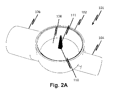
[0030] Fig. 2A shows a pressure pod 101 according to the disclosed
embodiments. The pressure pod 101 has a first port 106 and a second port 104.
In
the present embodiment, the first port 106 is larger to accommodate a larger
tube in
an embodiment where the pressure pod 101 is to be directly connected to a pump
tube portion. The second port 104 is for connection to a smaller diameter
tube. A
diaphragm 108 seals a portion of a continuous lumen spanning between 106 and
104 with a cross-sectional area that is substantially uniform to reduce the
risk of
4
CA 03132860 2021-09-07
WO 2020/190635 PCT/US2020/022341
dead zones that can cause clotting/coagulation when the pressure measurement
device is used for measuring blood pressure. Alternatively, the cross section
may
vary as a result of the positive draft angles used to allow the mold pins to
be
removed so that there is a narrowing from one port toward the center of the
pod and
then a widening of the cross section on the way to the opening of the other
port. It is
possible for the pins to be shaped such that the flow area is largest in the
middle
despite the positive draft angles, but certain benefits accrue where the area
changes
little, including the reduction in turbulence otherwise caused by flow
deceleration.
Note that flow area inserts may be used to adapt tubes to the ports so that
the
requirements of the beneficial molding process described herein do not have to
constrain choices for connecting tubes to the pod.
[0031] The pressure in the lumen causes movement/deformation of the
diaphragm 108, which in turn causes a movement of an indicator 110 configured
as
a protrusion on the diaphragm 108. The surface of the indicator 110 is
embossed or
imprinted by markings 111 so that the movement of the indicator 110 can be
optically
monitored by a measurement device (not shown) that engages a recess rim 102 of
the pressure pod 101. The engagement is suitable for immobilizing the support
of
the diaphragm 108 and helping to ensure accurate measurement.
[0032] Fig. 2B shows another pressure pod 103 according to the disclosed
embodiments. The pressure pod 103 is the same as the pressure pod 101 except
that it does not include the indicator 110. Instead, movement/deformation of
the
diaphragm 108 is detected by optically monitoring embossed or imprinted
markings
114 on the surface of the diaphragm 108. Other alternative embodiments may
optically monitor markings on both a diaphragm and an indicator configured as
a
protrusion on the diaphragm.
[0033] In one embodiment, the markings on the diaphragm 108 and/or the
indicator 110 may be painted thereon after the pressure pod has been molded.
In
one embodiment, the markings on the diaphragm 108 and/or the indicator 110 are
etched by a laser. In one embodiment, the markings on the diaphragm 108 and/or
the indicator 110 may be glued/attached thereon. In further embodiments, the
markings may be printed on the diaphragm 108 and/or the indicator 110 such as
by
means of silk-screening or inkjet. In still other embodiments, the markings on
the
diaphragm 108 and/or the indicator 110 may be molded into the diaphragm 108 or
the indicator 110. Note that for molding, the markings may have a neutral or
positive
CA 03132860 2021-09-07
WO 2020/190635 PCT/US2020/022341
draft to permit easy separation from the mold. For example, a staircase may be
formed on a pyramidal indicator. The staircase may be made to stand out by
illuminating to create shadows on each step.
[0034] Figs. 3A and 3B show respective views of an optical transducer 141
configured for engagement with the pressure pod 101 of Fig. 2A, and Fig 3C
shows
the optical transducer of Figs. 3A and 3B when assembled on the pressure pod
101
of Fig. 2A, according to the disclosed embodiments. The optical transducer 141
has
a support insert 152 that is configured to fit within the recess rim 102 of
the pressure
pod 101 to locate it precisely relative to a supporting transducer element.
[0035] The support insert 152 supports a camera/light source body 142 and
an arm 146. The arm 146 includes an opening for fastener 150 so that the
optical
transducer 141 may be fastened to another assembly in a system. The
camera/light
source 142 includes a light source 145, a camera 144, and a connector 148 for
camera 144. When the support insert 152 is fitted within the recess rim 102 of
the
pressure pod 101, the light source 145 can reflect light on the indicator 110
so that
the camera 144 can take images of the indicator 110 when controlled by a
controller
via the connector for camera 148.
[0036] The body of the camera/light source 142 may be spaced apart (as
indicated at 158) from the rim 153 of the support insert 152 so as not to
interfere with
displacement of the diaphragm 108.
[0037] In some embodiments, the camera 144 may include a Moire filter.
Generally, a Moire filter is a filter with alternating transparent and opaque
(non-light-
transmitting) portions forming, for example, concentric circles, a grid,
parallel lines,
etc. When the markings on the indicator 110 have a same or similar pattern as
the
Moire filter and are misaligned with respect to the Moire filter, a Moire
pattern may be
observed in the images of the markings obtained by the camera 144 through the
Moire filter. Generally, a Moire pattern is formed by placing two templates of
alternating transparent and opaque areas against each other. When the template
patterns are misaligned from a certain point of view, the superposition and
interference of the template patterns appears from that point of view as
alternating
light and dark zones that are larger/coarser than the original template
patterns, and
the misalignment causes the resulting pattern to appear to run. The resulting
pattern
is indicative of a beat frequency of the interference of the template patterns
which is
lowers than the frequency of the alternating patterns in the templates. Using
the
6
CA 03132860 2021-09-07
WO 2020/190635 PCT/US2020/022341
resulting pattern, a relative position may be determined, for example, as
disclosed in
US Patent Number 5052807.
[0038] In one embodiment, at least two cameras with respective Moire filters
are configured to obtain respective Moire patterns by taking images of the
indicator
110. In these embodiments, the Moire patterns may be used in combination for
determining a movement of the indicator 110 and/or calibrating the pressure
measurement device.
[0039] Fig. 3D shows the appearance of a filtered pattern detected by the
optical transducer 141 when the camera 144 includes a Moire filter with a
pattern of
parallel lines and is misaligned with parallel line markings on the indicator
110. In
one embodiment, a pre-determined function may be used to relate a change in
the
Moire pattern detected by the camera 144 with a movement of the indicator 110.
The pre-determined function may be compiled by training a controller of the
optical
transducer 141 with known movements of the indicator 110 and the resulting
Moire
patterns obtained by the camera 144.
[0040] Fig. 4A shows an optical transducer 170 configured for engagement
with the pressure pod 103 of Fig. 2B and Fig. 4B shows the optical transducer
170 of
Fig. 4A when assembled on the pressure pod 103 of Fig. 2B according to the
disclosed embodiments. Optical transducer 170 includes a support insert 178
that is
configured to fit within the recess rim 102 of the pressure pod 103.
[0041] The support insert 178 supports, between two pillars 176, a camera
172 with a camera lens 174 facing the diaphragm 108 of the pressure pod 103 so
that the camera 172 can take images of the diaphragm 108 when controlled by a
controller. The pillars define notches 177 that may allow for the use of a
light source
outside the support insert 178. Alternatively, the body of the camera 172 may
have
an integrated light source. An outside light source may provide better for
shadowing
molded-in ridges to form the indicator.
[0042] In embodiments, the camera lens 174 includes a Moire filter including
alternating transparent and opaque portions forming, for example, concentric
circles,
a grid, parallel lines, etc. When the markings on the diaphragm 108 have a
same or
similar pattern as the Moire filter and are misaligned with respect to the
Moire filter, a
Moire pattern may be observed in the images of the markings obtained by the
camera 172 through the Moire filter of the camera lens 174. Fig. 4C shows the
appearance of a filtered pattern detected by the optical transducer 170 when
the lens
7
CA 03132860 2021-09-07
WO 2020/190635
PCT/US2020/022341
174 includes a Moire filter with a pattern of concentric circles and is
misaligned with
same or similar concentric circle markings on the diaphragm 108.
[0043] In embodiments, the movement/deformation of the diaphragm may be
detected by using the disclosed Moire patterns in super-resolution imaging.
Super-
resolution imaging refers to improving the resolution of images obtained by an
imaging system. In one embodiment, when the resolution of the markings on a
marker or diaphragm is beyond the diffraction limit, a Moire filter that is
coarser
(lower-resolution) than the markers may be used to obtain images from which
the
high-resolution markings can be inferred. Accordingly, more accurate pressure
measurement may be accomplished.
[0044] One embodiment provides a pressure measurement device that
determines a pressure based on Moire patterns resulting from taking images of
markings on a diaphragm of a pressure pod as well as markings on an indicator
on
the diaphragm. The Moire patterns may be obtained by respective cameras
including respective filters to obtain images of the diaphragm and images of
the
protrusion on the diaphragm.
[0045] Figs. 4D and 4E show an alternative pressure measurement device
that includes the pressure pod 101 of Fig. 2A and a camera 200 for monitoring
movements of the indicator 110. A support insert 178 is configured to fit
within the
recess rim 102 of the pressure pod 101 and includes a background screen 204
against which images of the indicator 110 can be taken. A camera lens 202 of
the
camera 200 may be oriented to face the background screen 204 as shown in Fig.
4D. Alternatively, the camera lens 202 may be oriented to be in parallel with
the
background screen 204 as shown in Fig. 4E, and a beam director 2001 may be
configured to direct a beam from the indicator 110 to the camera 200 so that
the
camera 200 may take images of the indicator 110 against the background screen
204.
[0046] One embodiment provides functionality to prevent and/or account for
any "creep" in the diaphragm 108. Creep, or plastic deformation, occurs when
the
diaphragm 108 gradually generates a lower elastic rebound after being deformed
over time. This produces hysteresis in the pressure signal. As a result of
creep, the
pressure signal from a calibration becomes less related to the pressure signal
after
calibration. In embodiments, a negative pressure is periodically introduced to
exercise the diaphragm 108 (for example, for 1% of the duty cycle) to avoid
creep.
8
CA 03132860 2021-09-07
WO 2020/190635 PCT/US2020/022341
In other embodiments, control check algorithms are used to determine if creep
occurs. One embodiment minimizes diaphragm deformation in configurations in
which the material of which the diaphragm is made is prone to creep. This
translate
to a reduced susceptibility of the apparatus to respond variably over time to
pressure
in the pressure pod due to the creep, and to a smoother monotonic relationship
between pressure and diaphragm deformation/movement. The problems relating to
creep may also be overcome by suitable choice of material. For example, a
material
which is not subject to creep may be used for the diaphragm 108.
Alternatively, or in
combination with such a material selection, the wall thickness of the
diaphragm may
be reduced.
[0047] In embodiments, the material and/or thickness of the diaphragm 108 is
selected to further account for hoop strength in pressure measurement. Hoop
strength refers to the stress produced by the pressure of the fluid in a pipe
and
applied circumferentially to the pipe wall in a plan perpendicular to the
pipe's
longitudinal axis. A vessel or tube with a substantially circular or
elliptical cross-
section has significant hoop strength requiring a great deal of material
strain to
displace a diaphragm embedded thereon such as the diaphragm 108. In addition,
the thickness of the diaphragm 108 affects the degree of strain to which the
material
of the tube or vessel must be subjected to generate a displacement/deformation
of
the diaphragm 108. In embodiments, the diaphragm 108 may be formed of a
flexible
polymer.
[0048] Figs. 5A and 5B show a pressure pod with a straight fluid channel with
ports 104 and 106, a diaphragm 108, and a recess rim 102 as described with
regard
to other embodiments and similar to one described in International Patent
Publication W02012166980 ('980). Figs. 5C and 5D show left hand and right hand
90 degree turn pods with channels shaped to bend at right angles. As may be
confirmed by inspection of Figs. 6A through 6C, the pods of Figs. 5A and 5B
may be
molded with an integral diaphragm in the manner described in '980. Fig. 6C
shows a
pod 701C with a fluid channel that turns at an angle between 0 and 90 degrees.
It
can be seen that injection molding pins may be used to form the inlet and
outlet
channels as well as the pressure measurement chamber in the fluid channel
below
and adjacent the diaphragm 108. Also, it will be observed that the diaphragm
may be
formed in the molding of the entire pressure pod of any of the embodiments
shown
at 701A-701C.
9
CA 03132860 2021-09-07
WO 2020/190635 PCT/US2020/022341
[0049] Fig. 6D shows a cross-section of a pod portion having a channel 310
defined by a channel wall 117 and a diaphragm 115 integrally formed with the
channel wall 117 for example by injection molding. When there is a negative
pressure in the channel, the diaphragm 115 flexes and is pulled inwardly
toward the
channel as shown in Fig. 6E. When there is a positive pressure in the channel
310,
the diaphragm 115 flexes and is pushed outwardly as shown in Fig. 6F. The
flexion
of the diaphragm 115 is attended by strain of the material due to the finite
thickness
of the diaphragm 115. This strain can be reduced for a given degree of flexion
by
making the diaphragm 115 thinner as shown in Figs. 6G through 6J. By reducing
the
strain, the magnitude of creep can be reduced. Figs. 6K shows a molding
operation
for a pressure pod 501 shown in cross-section. A pin 125 forms an integral
diaphragm 109A in cooperation with a pin 126 by molding. Other parts of the
mold
are not shown. To make the diaphragm thin, an operation known as coining may
be
employed by, after flowing molten plastic through the mold passage
corresponding to
the diaphragm 109A, forcing the pin 125 downwardly to reduce the volume of
this
mold passage and press the still softened plastic out of the mold passage as
shown
in Fig. 6L.
[0050] Figs. 7A and 7B show a pressure sensor 500 that includes a pressure
pod 501 and a transducer 503. The transducer 503 has a cylindrical housing 511
that attaches to the pressure pod 501 by means of a vacuum attachment system
with Fig. 7A showing the pod 501 ready for engagement with the transducer 503
and
Fig. 7B showing the pressure pod 501 engaged with the transducer 503. The
vacuum attachment system draws air through a vacuum line 284 to generate a
vacuum between the pod 501 diaphragm 108 and a force input plate 512. The
force
input plate 515 has a strain gauge 515 that converts displacement of the
diaphragm
108 into a pressure indication of fluid pressure in the channel 310 of the
pressure
pod 501. As a result of the vacuum, the force input plate 512 follows the
diaphragm
when a positive pressure in the channel 310 pushes against it as well as when
a
negative pressure in the channel 310 pulls the diaphragm 108 in the opposite
direction. In this way, the strain gauge 515 is able to register both negative
and
positive pressure in the channel. By using a vacuum in this manner, it is
possible for
the pod 501 and diaphragm 108 to be separate from the transducer 503 such
that,
for example, the pod 501 can be a replaceable component and the transducer 503
can be a permanent component. This provides a mechanism for reducing costs of
a
CA 03132860 2021-09-07
WO 2020/190635 PCT/US2020/022341
system in which the use of a channel that must be replaced to ensure sterility
¨ a
sterile disposable component ¨ can be made inexpensively while the more
expensive transducer can be a non-replaceable component.
[0051] Note that the vacuum system includes a wall 520 of the pod 501 that
provides a sealing surface 508 surrounding a recess 506 into which the
transducer
503 cylindrical housing 511 fits to form a vacuum-tight seal so that a vacuum
can be
maintained between the diaphragm 108 and the outer surface of the force input
plate
512. As a result of the vacuum-tight seal, only small amount of air needs to
be
drawn to maintain the vacuum permitting the use of a single vacuum line 284.
[0052] A vacuum applied to a vacuum line 284 draws air continuously from the
minimal gap between the diaphragm 108 and the force input plate 512. The force
input plate 512 may be rippled as indicated by undulations 514 to permit the
force
input plate 512 to flex more easily due to pressure, both negative and
positive
exerted by movement of the diaphragm.
[0053] Note that the transducer 503 may be used with any of the
embodiments of Figs. 6A through 7C as well as with the pressure pods that are
described in '980.
[0054] Figs. 8A through 8F show details of a pressure sensor 400 that
includes a pod 402 and a transducer assembly 404. The pod 402 may be the same
as the various pods described herein, for example, the pod 402 may have the
configuration of the pod 501 illustrated in Figs. 5A to 5C. It will be
evident, however,
that other configurations are also usable in the present embodiment. The pod
402
has a diaphragm 108 that is held in contact with a force input plate 421 of a
sensor
unit 418. The sensor unit 418 may be a transducer that generates a signal in
response to detection of force. The force input plate 421 is held in contact
with the
diaphragm 108 of the connected pod by a vacuum supplied through an adapter
412.
The adapter has a flange 423 that is used, in part, to preload, by means of a
spring,
the adapter 412 within a housing. The diaphragm 108 lies at the base of a well
413
surrounded by a wall 414 contacted by a seal 401 of the adapter 412, the seal
being
held against the wall 414 by the force of the vacuum. Thus the adapter seal
401 is
highly flexible (for example, of silicone) and helps to maintain the vacuum
between
the pod 402 diaphragm 108 and the force input plate 421. The vacuum is applied
to
through the adapter 412 which supports and seals the sensor unit 418. The seal
401
may be of a resilient polymer such as silicone. Preferably the seal is shaped
so that
11
CA 03132860 2021-09-07
WO 2020/190635 PCT/US2020/022341
it can be compliant and flexible and such that air pressure presses it firmly
against
the wall 414 of the well 413 surrounding the diaphragm 108.
[0055] The vacuum source (such as a vacuum air pump, not shown) may be
connected to a vacuum connector 406. A vacuum supply line 408 draws air from
the
space between the diaphragm 108 and the force input plate 421 through a bore
inside the adapter 412, and therefore not visible in the drawings. The bore
runs
continuously through the adapter 412 from the vacuum supply line 408 to a bore
opening 415. Thus, air is drawn through the bore opening 415 to maintain the
vacuum. This maintains continuous contact between the diaphragm 108 and the
force input plate 421 during pressure measurements even when the pressure in
the
channel 310 is negative. The adapter 412 has a hard end 417 that is seated on
the
perimeter of the diaphragm 108 by the vacuum force. The plane of the force
input
plate 421 is coplanar with a plane defined by the surface of the adapter 412
hard end
417.
[0056] The transducer assembly 404, includes the sensor unit 418 and the
adapter 412. The transducer assembly 404 may be a permanent fixture, for
example
a component of a treatment machine, other types of fixed devices, and even non-
treatment machines. The pod 402 may be a replaceable component and may be
included as part of any of a fluid circuit. For example, see the discussion of
Fig. 11
below. The connector 406 connects a vacuum supply line 408 to a vacuum source
(not shown). The vacuum supply line 408 is connected to the adapter 412, which
is a
generally cylindrical member that holds a sensor unit 418. The adapter 412 has
a
bore through it that opens at an end thereof indicated at 414.
[0057] Fig. 8J shows a schematically a portion of the sensor unit. The sensor
unit 418 may have a fluid-filled container 442 with the force input plate 421
on one
end and a strain gauge 440, inside the container which has an opening 444 on
an
end opposite the force input plate on the other end. Thus, the strain gauge
blocks
the egress of fluid from the container 442 such that when the force input
plate 421 is
flexed it applies a negative or positive force to the strain gauge. The area
of the
force input plate 421 is relatively large and the area of the strain gauge is
small such
that the flexion of the force input plate 421 is limited. This constrains the
amount of
strain that is suffered by the force input plate and correspondingly by the
diaphragm
which limits the effect of creep on the response of the diaphragm. Thus, the
force on
the diaphragm is spread over a large area but the output transferred to the
12
CA 03132860 2021-09-07
WO 2020/190635 PCT/US2020/022341
incompressible fluid is spread over a small area. Since the strain gauge
itself is small
any flexion in it is relatively large compared to the flex in the force input
plate 421 so
that the force input plate 421 displacement is reduced.
[0058] Figs. 8C through 8F show the pod 402 ready to receive the transducer
assembly 404 just prior to their mutual engagement which is shown if Figs. 8A
and
8B. Fig. 8G shows the sensor unit 418 alone and Fig. 8H shows the sensor unit
418
separated from the adapter 412. The sensor unit has electrical leads indicated
at 419
which are terminated at an electrical connector 411.
[0059] Fig. 9 shows a fluid circuit 300 with three pressure pods (fluid
circuit
portions as is 105) 304, 306, and 308 attached together by a single frame
3310. A
pumping portion 302 and arterial blood line 314 and venous blood line 318, and
pre-
and post-filter lines 312 and 316 to and from filter 320, respectively, can be
pre-
attached so that the components can all be simultaneously positioned and
attached
to a treatment machine 9330. This attachment may connect all the pods 304,
306,
and 308 with transducer fixtures 342 as well as a peristaltic pump actuator
332. The
connections between arterial 314 and venous 318 blood lines are shown
figuratively
as is a patient 325. An adapter 311 may be provided to allow connection of
small
diameter tubes as required, in embodiments in which the pod chamber is the
same
size as one of the pins used to mold the pod. Figs. 10A and 10B show
components
for fabricating a pressure pod according to embodiments of the disclosed
subject
matter. Figs. 10C and 10D show stages in the manufacture of a pressure pod
according to embodiments of the disclosed subject matter.
[0060] Note that the transducer fixtures 342 may correspond to any of the
transducer embodiments disclosed herein, for example, they may include the
transducer assembly 404. Thus, in this example, the attachment of the fluid
circuit
300 with the transducer fixtures 342 may form three of the pressure sensors
400.
[0061] Fig. 10A shows a section view of the pressure sensor 400 and includes
an enclosure 454 that holds a spring (not shown), within an annular space
between
the enclosure 454 and a base 460. Referring now also to Figs. 10B through 10D,
the spring nests in the annular recess 462 at one end and abuts a rim 475 in
the
enclosure 454 at the spring's other end. The spring may be a coil spring (not
shown).
The spring occupies an annular volume indicated at 452. The flange 423 is
forced
against the base 460 by the spring and the enclosure 454 holds the opposite
end of
the spring such that the flange 423 is urged toward the base until a beveled
edge
13
CA 03132860 2021-09-07
WO 2020/190635 PCT/US2020/022341
448 on the inside of the flange nests, and is centered and held, by a conical
surface
450 in the base. This arrangement makes the adapter 412 center itself with
respect
to the base when the pod 402 is not urged against it. An opening 455 in the
base
460 is larger than the body of the adapter 412 so that it can float within the
opening
455 and move around along axes perpendicular to the longitudinal axis of the
pressure sensor 400. The freedom of movement allows the pod 402 and the hard
end 417 to auto-locate with respect to each other when they are pushed
together to
engage the pod 402 and pressure sensor 400.
[0062] Fig. 10B shows the hard end 417 of the adapter 412 enlarged so that
an annular recess 445 is visible. This spreads the vacuum suction applied
through
the bore opening 415 over a surface of the hard end 417 thereby maintaining
contact
between the force input plate 421 and the diaphragm 108. Mounting holes 461
allows the enclosure 454 to be bolted to a platform (not shown).
[0063] Fig. 11 is a block diagram of an example computer system 1000
according to an embodiment. In various embodiments, all or parts of system
1000
may be included in a medical treatment device/system such as a renal
replacement
therapy system. In these embodiments, all or parts of system 1000 may provide
the
functionality of a controller of the medical treatment device/systems. In some
embodiments, all or parts of system 1000 may be implemented as a distributed
system, for example, as a cloud-based system.
[0064] System 1000 includes a computer 1002 such as a personal computer
or workstation or other such computing system that includes a processor 1006.
However, alternative embodiments may implement more than one processor and/or
one or more microprocessors, microcontroller devices, or control logic
including
integrated circuits such as ASIC.
[0065] Computer 1002 further includes a bus 1004 that provides
communication functionality among various modules of computer 1002. For
example, bus 1004 may allow for communicating information/data between
processor 1006 and a memory 1008 of computer 1002 so that processor 1006 may
retrieve stored data from memory 1008 and/or execute instructions stored on
memory 1008. In one embodiment, such instructions may be compiled from source
code/objects provided in accordance with a programming language such as Java,
C++, C#, .net, Visual BasicTM language, LabVIEW, or another structured or
object-
oriented programming language. In one embodiment, the instructions include
14
CA 03132860 2021-09-07
WO 2020/190635 PCT/US2020/022341
software modules that, when executed by processor 1006, provide renal
replacement therapy functionality according to any of the embodiments
disclosed
herein.
[0066] Memory 1008 may include any volatile or non-volatile computer-
readable memory that can be read by computer 1002. For example, memory 1008
may include a non-transitory computer-readable medium such as ROM, PROM,
EEPROM, RAM, flash memory, disk drive, etc. Memory 1008 may be a removable
or non-removable medium.
[0067] Bus 1004 may further allow for communication between computer 1002
and a display 1018, a keyboard 1020, a mouse 1022, and a speaker 1024, each
providing respective functionality in accordance with various embodiments
disclosed
herein, for example, for configuring a treatment for a patient and monitoring
a patient
during a treatment.
[0068] Computer 1002 may also implement a communication interface 1010
to communicate with a network 1012 to provide any functionality disclosed
herein, for
example, for alerting a healthcare professional and/or receiving instructions
from a
healthcare professional, reporting patient/device conditions in a distributed
system
for training a machine learning algorithm, logging data to a remote
repository, etc.
Communication interface 1010 may be any such interface known in the art to
provide
wireless and/or wired communication, such as a network card or a modem.
[0069] Bus 1004 may further allow for communication with a sensor 1014
and/or an actuator 1016, each providing respective functionality in accordance
with
various embodiments disclosed herein, for example, for measuring signals
indicative
of a patient /device condition and for controlling the operation of the device
accordingly. For example, sensor 1014 may provide a signal indicative of a
viscosity
of a fluid in a fluid circuit in a renal replacement therapy device, and
actuator 1016
may operate a pump that controls the flow of the fluid responsively to the
signals of
sensor 1014.
[0070] According to first embodiments, the disclosed subject matter includes a
method of pressure measurement that includes determining a Moire pattern
resulting
from an interference of a Moire filter with markings on a diaphragm of a
pressure
pod. The method includes determining a movement or deformation of the
diaphragm
based on the Moire pattern and determining a fluid pressure in the pressure
pod
based on the movement or deformation of the diaphragm.
CA 03132860 2021-09-07
WO 2020/190635 PCT/US2020/022341
[0071] In variations thereof, the first embodiments include ones in which the
Moire filter comprises concentric transparent and opaque circles. In
variations
thereof, the first embodiments include ones in which diaphragm has concentric
transparent and opaque circles. In variations thereof, the first embodiments
include
ones in which the markings on the diaphragm are engraved or embossed.
[0072] According to second embodiments, the disclosed subject matter
includes a method of pressure measurement, the method including determining a
Moire pattern resulting from an interference of a Moire filter with markings
on a
protrusion on a diaphragm of a pressure pod. The method includes determining a
movement of the protrusion on the diaphragm based on the Moire pattern and
determining a fluid pressure in the pressure pod based on the movement of the
protrusion on the diaphragm.
[0073] In variations thereof, the second embodiments include ones in which
the Moire filter comprises parallel transparent and opaque lines. In
variations thereof,
the second embodiments include ones in which the markings on the protrusion on
the diaphragm comprise parallel transparent and opaque lines. In variations
thereof,
the second embodiments include ones in which the markings on the protrusion on
the diaphragm are engraved or embossed.
[0074] According to third embodiments, the disclosed subject matter includes
a method of pressure measurement that includes determining a first Moire
pattern
resulting from an interference of a first Moire filter with markings on a
diaphragm of a
pressure pod. The method includes determining a movement or deformation of the
diaphragm based on the first Moire pattern. The method includes determining a
second Moire pattern resulting from an interference of a second Moire filter
with
markings on a protrusion on the diaphragm of the pressure pod. The method
includes determining a movement of the protrusion on the diaphragm based on
the
second Moire pattern and determining a fluid pressure in the pressure pod
based on
the movement or deformation of the diaphragm and the movement of the
protrusion
on the diaphragm.
[0075] In variations thereof, the third embodiments include ones in which the
first Moire filter comprises concentric transparent and opaque circles. In
variations
thereof, the third embodiments include ones in which markings on the diaphragm
comprise concentric transparent and opaque circles. In variations thereof, the
third
embodiments include ones in which the markings on the diaphragm are engraved
or
16
CA 03132860 2021-09-07
WO 2020/190635 PCT/US2020/022341
embossed. In variations thereof, the third embodiments include ones in which
the
second Moire filter comprises parallel transparent and opaque lines. In
variations
thereof, the third embodiments include ones in which the markings on the
protrusion
on the diaphragm comprise parallel transparent and opaque lines. In variations
thereof, the third embodiments include ones in which the markings on the
protrusion
on the diaphragm are engraved or embossed.
[0076] In variations thereof, any of the embodiments include ones in which the
pressure pod includes a housing with a flow channel, the housing having a
single
wall forming a self-supporting structure with a defined flow channel
connecting two
ports in communication with the flow channel and the channel has one wall
portion of
the housing that is substantially thinner than a remainder of the housing, the
one wall
portion having a major dimension that is no larger than one of the two ports,
thus
permitting the housing to be closed by a molding operation and without
requiring the
attachment of separate parts to close the housing, the one wall portion
comprising
the diaphragm.
[0077] In variations thereof, any of the embodiments include ones in which the
one wall portion is circular. In variations thereof, the any embodiments
include ones
in which the one wall portion is integral with the remainder of the housing.
In
variations thereof, the any embodiments include ones in which the one wall
portion is
configured such that the flow channel housing can be closed with a single
molding
operation and without requiring the attachment of separate parts to close the
housing. In variations thereof, any of the embodiments include ones in which
the
ports are located on opposite sides of the channel with axes that are parallel
to a
major plane of the one wall portion. In variations thereof, any of the
embodiments
include ones in which the method is performed by an optical detector detecting
a
displacement of the one wall portion corresponding to negative as well as
positive
pressure within the channel. In variations thereof, any of the embodiments
include
ones in which the pressure pod is manufactured by providing first and second
major
mold parts having recesses defining major parts of the housing, inserting pins
in the
first and second major mold parts, the pins being shaped to define the flow
channel
of the pressure pod, one of the pins having a major face that defines an
internal
surface of the diaphragm, closing the first and second major mold parts with
the pins
therebetween and injection molding the housing and removing the pressure pod
from
the mold parts and withdrawing the pins from flow channel.
17
CA 03132860 2021-09-07
WO 2020/190635 PCT/US2020/022341
[0078] In variations thereof, any of the embodiments include ones in which the
removing opens ports in the housing that communicate through the housing. In
variations thereof, any of the embodiments include ones in which one of the
pins has
a major dimension that is larger than, equal in size to, the diaphragm. In
variations
thereof, any of the embodiments include ones in which one of the pins has a
major
dimension that is larger than, equal in size to, a diameter of the diaphragm.
In
variations thereof, any of the embodiments include ones in which the diaphragm
has
a projection on an outside surface thereof, the projection comprising the
protrusion.
[0079] In variations thereof, any of the first embodiments include ones in
which the method is performed by a controller of a system for measuring
pressure in
a fluid circuit. The system includes the pressure pod and an optical
displacement
measuring apparatus against which the pressure pod is immobilized, wherein the
diaphragm is optically monitored by the optical displacement measuring
apparatus.
[0080] In variations thereof, any of the first embodiments include ones in
which the optical displacement measuring apparatus is configured to generate a
signal responsively to displacement of the diaphragm, wherein the diaphragm is
configured to present a smooth internal surface to an internal flow path of
the
pressure pod, the internal flow path extending between the access of inlet and
outlet
ports of the pressure pod having a hydraulic diameter of no more than 15 mm at
all
points therethrough.
[0081] In variations thereof, any of the first embodiments include ones in
which an internal flow path of the pressure pod has a cross-section whose
aspect
ratio does not exceed three.
[0082] In variations thereof, any of the first embodiments include ones in
which the system comprises a housing that is a self-supporting inline pod
structure.
[0083] In variations thereof, any of the first embodiments include ones in
which an internal surface of a flow path in the pressure pod has a positive or
neutral
draft from any point toward at least one of an inlet port and an outlet port
of the
pressure pod and at all of said internal surface from said any one point to
said at
least one of the inlet port and the outlet port.
[0084] In variations thereof, any of the first embodiments include ones in
which the housing, including the diaphragm and the protrusion, are integral
and of
the same material such that they are configured to be molded as a single
element.
18
CA 03132860 2021-09-07
WO 2020/190635 PCT/US2020/022341
[0085] In variations thereof, any of the first embodiments include ones in
which one of the ports is larger than the other, and the larger port is
connected to a
fluid circuit for medical treatment, wherein the larger port is connected to a
pump
tubing segment and the other port is connected to a non-pump tubing segment.
[0086] In variations thereof, any of the first embodiments include ones in
which the housing has an annular rim and the optical displacement measuring
apparatus has a boss configured to mate with the annular rim.
[0087] In variations thereof, any of the first embodiments include ones in
which the flow path from port to port has a hydraulic diameter that varies by
not more
than 80%.
[0088] In variations thereof, any of the first embodiments include ones in
which the hydraulic diameter in the flow path remains at all points along the
flow
path, in a range between 4 mm and 10 mm.
[0089] In variations thereof, any of the first embodiments include ones in
which the flow includes a blood flow.
[0090] According to fourth embodiments, the disclosed subject matter includes
a pressure detection apparatus with a pressure pod having a chamber through
which
fluid flows and a diaphragm at the blind end of a recess with an access
defined by a
round ring, the diaphragm defining a wall of the chamber. A pressure
transducer plug
has a generally cylindrical wall with a vacuum channel formed therein and a
resilient
seal around a perimeter that forms a seal with an interior surface of the
recess
between the blind end and the access.
[0091] In variations thereof, the fourth embodiments include ones in which the
plug has a flexible wall that touches the diaphragm. In variations thereof,
the fourth
embodiments include ones that further include a vacuum pump connected to the
vacuum channel. In variations thereof, the fourth embodiments include ones in
which
the channel opens to a space between the flexible wall and the diaphragm such
that
the vacuum applied to the channel causes the flexible wall and the diaphragm
to be
held together and to flex together responsively to a pressure of fluid in the
chamber.
[0092] According to fifth embodiments, the disclosed subject matter includes a
pressure measurement apparatus with a pressure pod having a fluid channel
defined
in part by a diaphragm. The diaphragm is flat and is positioned in the base of
a well
that fits snugly over a pressure transducer plug, the transducer plug having a
force
input plate that lies adjacent the diaphragm when the well is fitted snugly
over the
19
CA 03132860 2021-09-07
WO 2020/190635 PCT/US2020/022341
pressure transducer plug. The pressure transducer plug has a bore connectable
to a
vacuum pump, the bore opening between the diaphragm and the force input plate
such that air can be evacuated from a space between the force input plate and
the
diaphragm. A resilient seal surrounds the plug and is positioned and shaped to
form
a seal with the well. The pressure transducer plug has a rigid ring portion
that is
seated at a perimeter of the diaphragm when air is evacuated from a space
between
the force input plate and the diaphragm. A surface of the rigid ring portion
being
coplanar with a surface of the force input plate and a surface of the
diaphragm.
[0093] In variations thereof, the fifth embodiments include ones in which the
pressure transducer plug has a strain gauge to which force is applied by said
force
input plate through an incompressible fluid contained by said pressure
transducer
plug.
[0094] In variations thereof, the fifth embodiments include ones in which an
area of the strain gauge is smaller than an area of the force input plate.
[0095] In variations thereof, the fifth embodiments include ones in which the
bore opens at said rigid ring portion.
[0096] In variations thereof, the fifth embodiments include ones that further
include a vacuum pump connected to said bore.
[0097] In variations thereof, the fifth embodiments include ones in which the
pressure transducer plug includes a pressure transducer and a cylindrical
adapter,
the adapter having the bore and rigid ring portion, the pressure transducer
having
the force input plate.
[0098] In variations thereof, the fifth embodiments include ones in which the
pressure pod is part of a disposable fluid circuit.
[0099] In variations thereof, the fifth embodiments include ones in which the
diaphragm applies a negative force to said force input plate when a negative
pressure is present in said fluid channel the negative force being responsive
to a
vacuum applied by said vacuum pump.
[0100] According to sixth embodiments, the disclosed subject matter includes
a pressure measurement apparatus with a pressure pod having a fluid channel
defined in part by a diaphragm. The diaphragm is flat and is positioned over a
pressure transducer plug and held in place by a vacuum, the transducer plug
having
a force input plate that lies adjacent the diaphragm. The pressure transducer
plug
has a bore connectable to a vacuum pump, the bore opening between the
CA 03132860 2021-09-07
WO 2020/190635 PCT/US2020/022341
diaphragm and the force input plate such that air can be evacuated from a
space
between the force input plate and the diaphragm. A resilient seal surrounds
the plug
and is positioned and shaped to form a seal with the diaphragm. The pressure
transducer plug having a rigid ring portion that is seated at a perimeter of
the
diaphragm when air is evacuated from a space between the force input plate and
the
diaphragm. A surface of the rigid ring portion is coplanar with a surface of
the force
input plate and a surface of the diaphragm.
[0101] In variations thereof, the sixth embodiments include ones in which the
pressure transducer plug has a strain gauge to which force is applied by said
force
input plate through an incompressible fluid contained by said pressure
transducer
plug.
[0102] In variations thereof, the sixth embodiments include ones in which an
area of the strain gauge is smaller than an area of the force input plate.
[0103] In variations thereof, the sixth embodiments include ones in which the
bore opens at said rigid ring portion.
[0104] In variations thereof, the sixth embodiments include ones that further
include a vacuum pump connected to said bore.
[0105] In variations thereof, the sixth embodiments include ones in which the
pressure transducer plug includes a pressure transducer and a cylindrical
adapter,
the adapter having the bore and rigid ring portion, the pressure transducer
having
the force input plate.
[0106] In variations thereof, the sixth embodiments include ones in which the
pressure pod is part of a disposable fluid circuit.
[0107] In variations thereof, the sixth embodiments include ones in which the
diaphragm applies a negative force to said force input plate when a negative
pressure is present in said fluid channel the negative force being responsive
to a
vacuum applied by said vacuum pump.
[0108] According to seventh embodiments, the disclosed subject matter
includes a method for measuring pressure. The method includes seating a
diaphragm of a fluid channel against a force input plate, the seating
including
applying a vacuum to a space between the force input plate and the diaphragm.
The
method further includes drawing the force input plate toward the fluid channel
by
applying a negative pressure in said fluid channel, said drawing being
responsive to
21
CA 03132860 2021-09-07
WO 2020/190635 PCT/US2020/022341
a force of said vacuum. The method includes applying a force to a strain gauge
through a fluid medium by means of said drawing the force input plate.
[0109] In variations thereof, the seventh embodiments include ones in which
the seating includes inserting the force input plate into a well with the
diaphragm at
its base.
[0110] In variations thereof, the seventh embodiments include ones in which
the applying a vacuum includes sealing a gap between the well and a support
plug to
which said force input plate is attached by means of a resilient sealing
member that
surrounds said support plug.
[0111] In variations thereof, the seventh embodiments include ones in which
the support plug contains said fluid medium.
[0112] It will be appreciated that the modules, processes, systems, and
sections described above can be implemented in hardware, hardware programmed
by software, software instruction stored on a non-transitory computer readable
medium or a combination of the above. For example, a method for measuring
pressure can be implemented, for example, using a processor configured to
execute
a sequence of programmed instructions stored on a non-transitory computer
readable medium. For example, the processor can include, but not be limited
to, a
personal computer or workstation or other such computing system that includes
a
processor, microprocessor, microcontroller device, or is comprised of control
logic
including integrated circuits such as, for example, an Application Specific
Integrated
Circuit (ASIC). The instructions can be compiled from source code instructions
provided in accordance with a programming language such as Java, C++, C#.net
or
the like. The instructions can also comprise code and data objects provided in
accordance with, for example, the Visual BasicTM language, LabVIEW, or another
structured or object-oriented programming language. The sequence of programmed
instructions and data associated therewith can be stored in a non-transitory
computer-readable medium such as a computer memory or storage device which
may be any suitable memory apparatus, such as, but not limited to read-only
memory (ROM), programmable read-only memory (PROM), electrically erasable
programmable read-only memory (EEPROM), random-access memory (RAM), flash
memory, disk drive and the like.
[0113] Furthermore, the modules, processes, systems, and sections can be
implemented as a single processor or as a distributed processor. Further, it
should
22
CA 03132860 2021-09-07
WO 2020/190635 PCT/US2020/022341
be appreciated that the steps mentioned above may be performed on a single or
distributed processor (single and/or multi-core). Also, the processes,
modules, and
sub-modules described in the various figures of and for embodiments above may
be
distributed across multiple computers or systems or may be co-located in a
single
processor or system. Exemplary structural embodiment alternatives suitable for
implementing the modules, sections, systems, means, or processes described
herein are provided below.
[0114] The modules, processors or systems described above can be
implemented as a programmed general purpose computer, an electronic device
programmed with microcode, a hard-wired analog logic circuit, software stored
on a
computer-readable medium or signal, an optical computing device, a networked
system of electronic and/or optical devices, a special purpose computing
device, an
integrated circuit device, a semiconductor chip, and a software module or
object
stored on a computer-readable medium or signal, for example.
[0115] Embodiments of the method and system (or their sub-components or
modules), may be implemented on a general-purpose computer, a special-purpose
computer, a programmed microprocessor or microcontroller and peripheral
integrated circuit element, an ASIC or other integrated circuit, a digital
signal
processor, a hardwired electronic or logic circuit such as a discrete element
circuit, a
programmed logic circuit such as a programmable logic device (PLD),
programmable
logic array (PLA), field-programmable gate array (FPGA), programmable array
logic
(PAL) device, or the like. In general, any process capable of implementing the
functions or steps described herein can be used to implement embodiments of
the
method, system, or a computer program product (software program stored on a
non-
transitory computer readable medium).
[0116] Furthermore, embodiments of the disclosed method, system, and
computer program product may be readily implemented, fully or partially, in
software
using, for example, object or object-oriented software development
environments
that provide portable source code that can be used on a variety of computer
platforms. Alternatively, embodiments of the disclosed method, system, and
computer program product can be implemented partially or fully in hardware
using,
for example, standard logic circuits or a very-large-scale integration (VLSI)
design.
Other hardware or software can be used to implement embodiments depending on
the speed and/or efficiency requirements of the systems, the particular
function,
23
CA 03132860 2021-09-07
WO 2020/190635 PCT/US2020/022341
and/or particular software or hardware system, microprocessor, or
microcomputer
being utilized. Embodiments of the method, system, and computer program
product
can be implemented in hardware and/or software using any known or later
developed systems or structures, devices and/or software by those of ordinary
skill in
the applicable art from the function description provided herein and with a
general
basic knowledge of digital control systems sensors and/or computer programming
arts.
[0117] Moreover, embodiments of the disclosed method, system, and
computer program product can be implemented in software executed on a
programmed general purpose computer, a special purpose computer, a
microprocessor, or the like.
[0118] It is, thus, apparent that there is provided, in accordance with the
present disclosure, pressure measurement devices, methods, and systems
including
control system which may include programmable processors and related
effecters.
Many alternatives, modifications, and variations are enabled by the present
disclosure. Features of the disclosed embodiments can be combined, rearranged,
omitted, etc., within the scope of the invention to produce additional
embodiments.
Furthermore, certain features may sometimes be used to advantage without a
corresponding use of other features. Accordingly, Applicants intend to embrace
all
such alternatives, modifications, equivalents, and variations that are within
the spirit
and scope of the present invention.
[0119] Furthermore, certain features of the disclosed embodiments may
sometimes be used to advantage without a corresponding use of other features.
Accordingly, Applicants intend to embrace all such alternatives,
modifications,
equivalents, and variations that are within the spirit and scope of the
present
disclosure.
24