Note : Les descriptions sont présentées dans la langue officielle dans laquelle elles ont été soumises.
CA 03133567 2021-09-14
WO 2020/150719
PCT/US2020/014299
SYSTEMS AND METHODS FOR PRODUCING MAGNETICALLY RECEPTIVE
LAYERS AND MAGNETIC LAYERS FOR USE IN SURFACE COVERING
SYSTEMS
Field of the Invention
The present invention pertains to the art of surface coverings, and, more
particularly to
systems and methods for producing magnetically receptive layers and magnetic
layers for use
in surface covering systems for interior and exterior applications.
Background
In the field of modular floor covering unit installation, existing methods of
installing such
floor coverings typically involve a very labor and material intensive process.
The process
involves preparing a supporting surface, e.g., subfloor, and individually
gluing down floor
covering units using an adhesive. The adhesive is heavy, difficult to apply,
costly, difficult to
remove, and prone to failure. Additional problems include moisture migration,
mold,
cracking, etc. Using this prior art method, adhesive must be applied to the
entire supporting
surface or the entire underside of a floor covering unit. This process is
costly in both labor
and money and creates additional costs if floor covering units are to be
replaced or removed.
Another installation technique involves so-called floating floors that are
susceptible to
movement, buckling, and other issues.
Another method known in the art for installing modular floor covering units
involves using
adhesive connectors to connect modular floor covering units with adjacent
units. Such
"connector systems" of the prior art allow the modular floor covering to
"float" on top of the
supporting surface. These prior art systems use an adhesive to hold the edges
of the adjacent
flooring units together. One such system and method is the SYSTEM FOR CARPET
TILE
INSTALLATION, U.S. Pat. No. 8,434,282, issued May 7, 2013 (Scott et al.). The
method
described in Scott et at. utilizes a one-sided pressure sensitive adhesive tab
that is
approximately 72 mm square that has a releasable protective layer to join four
sections of
modular flooring units together. There a several problems with using this
method to install a
modular floor covering including the replacement of individual floor covering
units, the
difficulty of installation, and the durability of the installation method.
There also exist other carpet seaming methods for joining together two
segments of floor
covering material along long, straight seams. Such methods include CARPET
SEAMING
1
CA 03133567 2021-09-14
WO 2020/150719
PCT/US2020/014299
APPARATUS AND METHOD OF UTILIZING THE SAME, U.S. Pat. No. 5,800,664,
issued September 1, 1998 (Covert), and SEAMING APPARATUS AND METHOD, U.S.
Pat. App. No. 14/309,632, filed June 19, 2014, (LeBlanc et al.). Additional
methods exist for
securing modular floor covering units together in a "floating floor"
configuration that
overcomes the problems and issues presented by the Scott et at. prior art.
Such methods
include MODULAR CARPET SEAMING APPARATUS AND METHOD, U.S. Pat. App.
No. 14/618,752, filed February 10, 2015, (Lautzenhiser et al.).
Improvements have been made to these systems and methods for securing floor
coverings
including using magnetic underlayments with magnetically receptive layers
secured or
affixed to the floor covering units. In addition to floor covering
applications, wall covering
applications, ceiling covering applications, roof and exterior wall covering
applications all
have different environmental concerns and considerations that must be factored
in
determining suitable materials having suitable properties for installation and
use. For
example, exterior applications will involve exposure to sun, wind, rain, storm
and other
weather-related conditions. "Surface" covering applications is used to broadly
refer to wall
and floor covering applications unless indicated otherwise.
Magnetic systems are often anisotropic meaning they are direction dependent
and may
require both the surface covering component and the underlayment component to
be arranged
in a directional manner. Such purely anisotropic systems suffer from several
drawbacks
including the need to place and align the components in a defined manner
adding to the
complexity and cost of installation and materials. Isotropic materials are
direction
independent. Plastic binders may be used in manufacturing pliable, flexible
magnetic sheets
but this generally results in lower magnetic strength.
Examples of such systems and methods are described in at least U.S. Pat. App.
16/013,902,
entitled MODULAR MAGNETICALLY RECEPTIVE WOOD AND ENGINEERED
WOOD SURFACE UNITS AND MAGNETIC BOX SYSTEM FOR COVERING FLOORS,
WALLS, AND OTHER SURFACES, filed June 20, 2018, Lautzenhiser et at.; U.S. Pat.
App.
15/083,255, entitled SYSTEM, METHOD, AND APPARATUS FOR MAGNETIC
SURFACE COVERINGS, filed March 28, 2016, Lautzenhiser et at.; in U.S. Pat.
App.
15/083,231, entitled SYSTEM, METHOD, AND APPARATUS FOR MAGNETIC
SURFACE COVERINGS, filed March 28, 2016, issuing as U.S. Pat. 10,189,236, on
January
29, 2019, Lautzenhiser et al.; and in U.S. Provisional Pat. App. 62/522,513,
entitled
2
CA 03133567 2021-09-14
WO 2020/150719
PCT/US2020/014299
MODULAR MAGNETIC WOOD AND ENGINEERED WOOD FLOORING UNITS
UTILIZING A MAGNET BOX SYSTEM FOR FLOORS, WALLS, AND OTHER
SURFACES, filed June 20, 2017, LeBlanc et at.
However, with the existing systems and methods for installing floor and wall
covering units,
and the systems and methods for producing such installation systems, there
exist issues when
combining different material types and in producing the necessary system
components.
Existing systems may not be sufficiently dimensionally or structurally stable
to be optimally
suited for high traffic or use conditions, such as in commercial applications.
The materials
and production processes used to make existing floor/wall covering systems may
not produce
floor covering units and installation materials with the desired durability
and stability
required for commercial applications and long-term installation. Moreover,
with existing
systems, including existing magnetic floor covering systems, the receptive and
magnetic
layers may be too thick or heavy or have too weak a magnetic remanence for
particular
applications.
What is needed is a system and method for producing modular floor covering
units that are
compatible with a wide range of floor covering material and supporting surface
types and
compositions. Additionally, what is needed is a system and method for
producing and
installing modular floor covering units that are dimensionally and
structurally stable, and are
suitable light with at least a minimum magnetic remanence for particular
installation
applications.
Also what is needed is a system and method suitable for wall covering
applications having
suitable magnetic strength or holding strength to maintain positioning of a
surface covering
component relative to an underlying and supporting underlayment component
adhered to a
wall or other supporting structure.
Also what is needed is a system and method suitable for exterior wall covering
applications
having suitable magnetic strength or holding strength to maintain positioning
of a surface
covering component relative to an underlying and supporting underlayment
component
adhered to an exterior wall or other supporting structure. The magnetic
strength or holding
strength of the system must be capable of withstanding shear force associated
with gravity as
well as wind and other environmental conditions, e.g., hurricanes, tornados,
falling debris,
animals.
3
CA 03133567 2021-09-14
WO 2020/150719
PCT/US2020/014299
Also what is needed is a system and method suitable for exterior roof covering
applications
having suitable magnetic strength or holding strength to maintain positioning
of a roof
covering component relative to an underlying and supporting underlayment
component
adhered to an exterior roof or other supporting structure. The magnetic
strength or holding
strength of the system must be capable of withstanding shear force associated
with gravity as
well as wind and other environmental conditions, e.g., hurricanes, tornados,
falling debris,
animals.
Also what is needed is a system and method suitable for wall, floor and
ceiling covering in
airplane applications having suitable magnetic strength or holding strength to
maintain
positioning of a surface covering component relative to an underlying and
supporting
underlayment component adhered to a wall ceiling or other supporting
structure. What is
needed is a thin, light weight system specially adapted for use in airplanes
having critical
requirements to minimize weight and depth of installation.
Also what is needed is a method of manufacturing magnetic surface covering
system
.. components using rare earth materials and adapted to align crystalline
structures to increase
strength and limit thickness.
Summary of Invention
The present invention provides a system, apparatus, and method for producing
magnetically
receptive layers and magnetic layers for use in surface covering systems. The
present
invention provides systems and methods for the manufacture of magnetically
receptive layers
and magnetic layers for use in surface covering systems that address issues
with existing
magnetic surface covering systems. The present invention comprises a two-
component
system comprising a magnetized underlay and an attracting floor covering unit.
The present invention provides a system and method for the production of
magnetically
receptive layers and magnetic underlayments as sheet goods for use in an
interchangeable
box system for attaching surface covering units to supporting surfaces. The
magnetically
receptive layers and magnetic underlayments of the present invention are
better suited to
installation in residential and commercial applications than the systems and
methods
disclosed in the prior art and provide benefits including increased
durability, improved
dimensional stability, and wider material compatibility than those used in
known surface
covering systems.
4
CA 03133567 2021-09-14
WO 2020/150719
PCT/US2020/014299
The materials, compounds, and processes used in the production of the
magnetically
receptive layers and magnetic underlayments of the present invention provide a
significant
improvement over the systems and methods of the prior art.
In a first embodiment, the present invention provides an isotropic
magnetically receptive
layer and an anisotropic magnetic underlayment. The magnetically receptive
layer is disposed
on the bottom or underside of a surface covering unit. The magnetic
underlayment is
disposed on a supporting surface. The anisotropic magnetic underlayment is
substantially
thinner than a similar isotropic magnetic underlayment but retains similar
hold
characteristics. For example, the anisotropic magnetic underlayment may be as
much as 50%
thinner while maintaining hold characteristics within 20% of an isotropic
magnetic
underlayment that is twice as thick.
In another embodiment, the present invention provides a "hybrid" magnetic
underlayment.
The "hybrid" magnetic underlayment comprises a blend of neodymium and ferrite
powder.
The "hybrid" magnetic underlayment may be dimensionally similar to a ferrite
powder
magnetic underlayment but may have a hold strength eight times greater than
the ferrite
powder magnetic underlayment. The "hybrid" magnetic underlayment may be
suitable for
applications where increased hold strength is required and where the increased
cost
associated with the neodymium powder is not a primary concern.
In another embodiment, the present invention provides a system and method for
applying a
magnetically receptive layer in a lower cost manner. A magnetically receptive
ferrite powder
blend may be mixed with a UV oil and sprayed onto a surface covering unit. The
ferrite
powder suspended in the UV oil is then set with high-powered UV lights. The
hardened UV
oil-ferrite powder blend acts as a magnetically receptive "B" side layer that
is permanently
bonded to the surface covering unit. Other oils or materials, such as PVC oil,
may also be
used.
The materials, compounds, and processes used in the production of the
magnetically
receptive layers and magnetic underlayments of the present invention provide a
significant
improvement over the systems and methods of the prior art.
In another embodiment, the present invention provides a system of surface
covering
components, the system when installed providing a quasi-permanent surface
covering, the
5
CA 03133567 2021-09-14
WO 2020/150719
PCT/US2020/014299
system comprising: a surface covering unit comprising an isotropic
magnetically receptive
layer; and an anisotropic magnetic underlayment disposed on a supporting
surface.
The anisotropic magnetic underlayment may be 0.5 mm in thickness. The
anisotropic
magnetic underlayment may further comprise: a magnetizable material; a binder;
and an oil.
The magnetizable material may comprise one of: ferrous iron powder, strontium
ferrite
powder, neodymium powder, and a neodymium and ferrous iron composite. The
binder may
comprise thermoplastic chlorinated polyethylene elastomer ("CPE"). The oil may
comprise
epoxidized soybean oil ("ESBO"). The anisotropic magnetic underlayment may be
a
calendared sheet good. The anisotropic magnetic underlayment may further
comprise a
magnetizable material having a Mesh size of 1-2.3 p.m.
In another embodiment, the present invention provides a magnetic underlayment
layer for
securing magnetically-receptive surface covering units on a supporting
surface, the magnetic
underlayment layer comprising: a neodymium powder; a binder; and an oil.
The magnetic underlayment layer may further comprise a plasticizer. The oil
may comprise
epoxidized soybean oil ("ESBO"). The ratio of the neodymium powder to the
binder and the
oil is less than 91% neodymium powder to 9% binder and oil. The magnetic
underlayment
layer may further comprise a ferrite powder. The ratio of the ferrite powder
to the
neodymium powder may be 50/50.
In another embodiment, the present invention provides a method for applying a
magnetically
receptive layer on a surface covering unit, the method comprising: adding a
receptive
material blend and an oil compound in a mixer; blending the receptive material
blend and the
oil compound to form a magnetically receptive oil blend; spraying the
magnetically receptive
oil blend onto a surface covering unit; and setting the magnetically receptive
oil blend onto
the surface covering unit.
The method may further comprise wherein the receptive material blend comprises
one of:
ferrous iron powder, strontium ferrite powder, neodymium powder, and a
neodymium and
ferrous iron powder composite. The method may further comprise wherein the oil
compound
comprises one of: ultraviolet ("UV") oil, and polyvinyl chloride ("PVC")
resin. The setting of
the magnetically receptive oil blend may further comprise setting the
magnetically receptive
oil blend by high intensity ultraviolet ("UV") lights. The setting of the
magnetically receptive
6
CA 03133567 2021-09-14
WO 2020/150719
PCT/US2020/014299
oil blend may further comprise setting the magnetically receptive oil blend by
high
temperature.
In another embodiment, the present invention provides a method for producing a
magnetically receptive sheet good for use in surface covering systems, the
method
comprising: combining a ferrite compound, a polymer, and a plasticizer in a
mixing vessel;
mixing the ferrite compound, the polymer, and the plasticizer at a desired
mixing temperature
and at a desired mixing pressure to form a magnetically receptive material;
and extruding the
magnetically receptive material at a desired extrusion temperature to form a
magnetically
receptive sheet good.
The method may further comprise annealing the magnetically receptive sheet
good. The
method may further comprise cold pressing the magnetically receptive sheet
good onto a
natural material building product. The method may further comprise hot
pressing the
magnetically receptive sheet good onto a synthetic material building product.
The method
may further comprise magnetizing the magnetically receptive sheet good. The
composition of
the magnetically receptive material may be selected from the group consisting
of: pure iron
powder (Fe) approximately 84%, chlorinated polyethylene elastomer polymer
(CPE)
approximately 15% and epoxidized soybean oil (ESBO) approximately 8%; Iron
powder
(Fe304) 90%, CPE 9% and plasticizer 1%; Mn-Zn (manganese/zinc) soft ferrite
powder
90%, CPE 9% and plasticizer 1%; 20 portions of CPE, 150 portions of stainless
iron powder;
30 portions of polyvinyl chloride, 18 portions of dioctyl terephthalate, 200
portions of
stainless iron powder; or PVC 16.5%, calcium carbonate 39%, iron powder 26.5%,
plasticizer
16%, and viscosity depressant & stabilizer 2%. The ferrite compound may be
strontium
ferrite, the polymer may be chlorinated polyethylene elastomer polymer (CPE),
and the
plasticizer may be epoxidized soybean oil (ESBO). The mixing may be performed
for
approximately 15 minutes, the desired mixing temperature may be under 120
degrees Celsius,
and the desired mixing pressure may be atmospheric pressure. The desired
extrusion
temperature may be 120 degrees Celsius and wherein the magnetically receptive
sheet good
may be extruded at 10 meters per minute. The mixing may be performed for 20-30
minutes,
the desired mixing temperature may be between 90-115 degrees Celsius, and the
desired
mixing pressure may be 0.4-0.7MPa. The magnetically receptive sheet good may
be extruded
at 4-10 meters per minute and the desired extrusion temperature may be 40-70
degrees
7
CA 03133567 2021-09-14
WO 2020/150719
PCT/US2020/014299
Celsius. The ferrite compound may be strontium ferrite having a particle size
of 38-62
microns.
In another embodiment, the present invention provides a rust resistant and
dimensionally
stable magnetically receptive sheet good for use in surface covering systems,
the sheet good
comprising: a ferrite compound; a plasticizer; and a polymer. The sheet good
may further
comprise wherein the ferrite compound is strontium ferrite, the polymer is
chlorinated
polyethylene elastomer polymer (CPE), and the plasticizer is epoxidized
soybean oil (ESBO).
The sheet good may further comprise wherein the strontium ferrite comprises a
particle size
of 38-62 microns.
In another embodiment, the present invention provides a method for producing a
magnetically receptive sheet good for use in surface covering systems, the
method
comprising: combining a ferrite compound, a polymer, and a plasticizer in a
mixing vessel;
mixing the ferrite compound, the polymer, and the plasticizer at a desired
mixing temperature
and at a desired mixing pressure to form a magnetically receptive material;
and extruding the
magnetically receptive material at a desired extrusion temperature to form a
magnetically
receptive sheet good; or applying a calendaring process to the magnetically
receptive layer to
form a magnetically receptive sheet good.
The method of the above embodiment may further comprise annealing the
magnetically
receptive sheet good. The method may further comprise cold pressing the
magnetically
receptive sheet good onto a natural material building product. The method may
further
comprise hot pressing the magnetically receptive sheet good onto a synthetic
material
building product. The method may further comprise magnetizing the magnetically
receptive
sheet good. The magnetically receptive layer may be magnetized to produce a
magnetized
underlayment adapted to magnetically engage and support a non-magnetized
receptive layer
component, the composition of the magnetically receptive material is selected
from the group
consisting of: for use in a calendaring process: 1) pure iron powder (Fe) or
strontium ferrite
approximately 89-91%, chlorinated polyethylene elastomer polymer (CPE)
approximately 8-
9% and epoxidized soybean oil (ESBO) approximately 1-2%; or 2) Iron powder
(ferrous iron
or ferrous ferric oxide, Fe304) approximately 89-91%, CPE approximately 8-9%
and
plasticizer approximately 1-2%; or for use in an extrusion process: 3) PVC
approximately
16.5%, calcium carbonate approximately 39%, iron powder approximately 26.5%,
plasticizer
approximately 16%, and viscosity depressant & stabilizer approximately 2%. The
8
CA 03133567 2021-09-14
WO 2020/150719
PCT/US2020/014299
magnetically receptive material may be used to produce a non-magnetized
receptive
component for use opposite a magnetized underlayment component, the
composition of the
magnetically receptive material is selected from the group consisting of: for
use in a
calendaring process: 1) Mn-Zn (manganese/zinc) soft ferrite powder
approximately 89-91%,
CPE approximately 8-9% and plasticizer approximately 1-2%; 2) approximately 20
portions
of CPE, approximately 150 portions of stainless iron powder, approximately 30
portions of
polyvinyl chloride (PVC), approximately 18 portions of dioctyl terephthalate,
approximately
200 portions of stainless iron powder; or for use in an extrusion process: 3)
PVC
approximately 16.5%, calcium carbonate approximately 39%, plasticizer
approximately 16%,
viscosity depressant & stabilizer approximately 2%, and at approximately 26.5%
one of: Mn-
Zn (manganese/zinc) soft ferrite powder; stainless iron powder; or ferrous
oxide or ferric
oxide powder. The ferrite compound may be strontium ferrite, the polymer is
chlorinated
polyethylene elastomer polymer (CPE), and the plasticizer is epoxidized
soybean oil (ESBO).
The mixing may be performed for approximately 15 minutes, the desired mixing
temperature
may be under 120 degrees Celsius, and the desired mixing pressure is
atmospheric pressure.
The desired extrusion temperature may be 120 degrees Celsius and the
magnetically receptive
sheet good may be extruded at 10 meters per minute. The mixing may be
performed for 20-
30 minutes, the desired mixing temperature may be between 90-115 degrees
Celsius, and the
desired mixing pressure may be between 0.4-0.7MPa. The magnetically receptive
sheet good
may be extruded at 4-10 meters per minute and the desired extrusion
temperature is 40-70
degrees Celsius. The ferrite compound may be strontium ferrite having a
particle size of 38-
62 microns.
In another embodiment, the present invention provides a rust resistant and
dimensionally
stable magnetically receptive sheet good for use in surface covering systems,
the sheet good
being magnetized to provide a magnetized underlayment for magnetically
engaging a non-
magnetized receptive layer component, the magnetized underlayment comprising:
for use in a
calendaring process: 1) pure iron powder (Fe) or strontium ferrite
approximately 89-91%,
chlorinated polyethylene elastomer polymer (CPE) approximately 8-9% and
epoxidized
soybean oil (ESBO) approximately 1-2%; or 2) Iron powder (ferrous iron or
ferrous ferric
oxide, Fe304) approximately 89-91%, CPE approximately 8-9% and plasticizer
approximately 1-2%; or for use in an extrusion process: 3) PVC approximately
16.5%,
calcium carbonate approximately 39%, iron powder approximately 26.5%,
plasticizer
9
CA 03133567 2021-09-14
WO 2020/150719
PCT/US2020/014299
approximately 16%, and viscosity depressant & stabilizer approximately 2%. The
ferrite
component may comprise a particle size of 38-62 microns.
In another embodiment the present invention provides a rust resistant and
dimensionally
stable magnetically receptive component for use in surface covering systems,
the
magnetically receptive component being a non-magnetized receptive layer
component for
magnetically engaging with a magnetized underlayment, the magnetically
receptive
component comprising: for use in a calendaring process: 1) Mn-Zn
(manganese/zinc) soft
ferrite powder approximately 89-91%, CPE approximately 8-9% and plasticizer
approximately 1-2%; 2) approximately 20 portions of CPE, approximately 150
portions of
stainless iron powder, approximately 30 portions of polyvinyl chloride (PVC),
approximately
18 portions of dioctyl terephthalate, approximately 200 portions of stainless
iron powder; or
for use in an extrusion process: 3) PVC approximately 16.5%, calcium carbonate
approximately 39%, plasticizer approximately 16%, viscosity depressant &
stabilizer
approximately 2%, and at approximately 26.5% one of: Mn-Zn (manganese/zinc)
soft ferrite
powder; stainless iron powder; or ferrous oxide or ferric oxide powder.
In a first embodiment related to a further inventive aspect, the invention
provides a surface
covering system, the system when installed providing a removably-fixed surface
covering,
the system comprising: a magnetic surface covering unit comprising a non-
magnetized,
isotropic magnetic receptive layer; and an anisotropically magnetized
underlayment disposed
on a supporting surface; wherein the magnetic surface covering unit is adapted
to be
magnetically attracted to and received opposite the anisotropically magnetized
underlayment
in a fixed installation and to be non-destructively removable from the
anisotropically
magnetized underlayment subsequent to fixed installation. In addition, the
invention may be
further characterized by one or more of the following features: the
anisotropically magnetized
underlayment is 0.5 mm in thickness and comprises magnetizable material having
a Mesh
size configured to have, when magnetized, enhanced magnetic attraction
property and
adapted for supporting the magnetic surface covering unit in a non-horizontal
fixed
installation, wherein the non-horizontal fixed installation is one of an
interior wall
installation, an exterior wall installation, an airplane interior cabin
installation, an exterior
roof installation, or an interior ceiling installation. The invention may be
further characterized
by the anisotropically magnetized underlayment comprises: a magnetizable
material
including an iron powder; a binder component; and an oil having properties
allowing for
CA 03133567 2021-09-14
WO 2020/150719
PCT/US2020/014299
rapid setting during manufacturing, whereby setting occurs at a normal line
speed in a
calendaring or extrusion process. The invention may be further characterized
by the
magnetizable material comprises one of: ferrous iron powder, strontium ferrite
powder,
neodymium powder, and a neodymium and ferrous iron powder composite. The
invention
may be further characterized by: wherein the binder comprises thermoplastic
chlorinated
polyethylene elastomer ("CPE"); wherein the oil comprises epoxidized soybean
oil
("ESBO"); wherein the anisotropically magnetized underlayment is one of a
calendared sheet
good or an extruded sheet good; wherein the anisotropically magnetized
underlayment
comprises a magnetizable material having a Mesh size of 1-2.3 p.m.
In a second embodiment the present invention provides a magnetized
underlayment for
securing magnetically-receptive surface covering units on a supporting
surface, the
magnetized underlayment comprising: a neodymium powder; a binder; and an oil
having
properties allowing for rapid setting during manufacturing, whereby setting
occurs at a
normal line speed in a calendaring or extrusion process.
The invention may be further characterized by one or more of: the magnetized
underlayment
further comprising a plasticizer; wherein the oil comprises epoxidized soybean
oil ("ESBO");
wherein the ratio of the neodymium powder to the binder and the oil is less
than 91%
neodymium powder to 9% binder and oil; wherein the magnetic underlayment layer
further
comprises a ferrite powder; wherein the ratio of the ferrite powder to the
neodymium powder
is 50/50. The invention may be further characterized by the ratio of the
neodymium powder
to the binder and the oil is selected based upon application considerations to
be one of: about
91% neodymium powder to about 9% binder and oil; about 81% neodymium powder to
about
19% binder and oil; about 71% neodymium powder to about 29% binder and oil;
about 61%
neodymium powder to about 39% binder and oil; or about 51% neodymium powder to
about
49% binder and oil.
In a third embodiment the invention provides a method for applying a
magnetically receptive
layer on a surface covering unit to produce a magnetically receptive surface
covering unit
adapted to be magnetically secured opposite a magnetized underlayment, the
method
comprising: adding a receptive material blend and an oil compound in a mixer;
blending the
receptive material blend and the oil compound to form a magnetically receptive
oil blend;
spraying the magnetically receptive oil blend onto a surface covering unit;
and setting the
magnetically receptive oil blend onto the surface covering unit. The invention
may be further
11
CA 03133567 2021-09-14
WO 2020/150719
PCT/US2020/014299
characterized by one or more of: wherein the receptive material blend
comprises one of:
ferrous iron powder, strontium ferrite powder, and neodymium powder, and
neodymium and
ferrous iron powder composite; wherein the oil compound comprises one of:
ultraviolet
("UV") oil, and polyvinyl chloride ("PVC") resin; wherein the setting of the
magnetically
receptive oil blend comprises rapidly setting the magnetically receptive oil
blend by high
intensity ultraviolet ("UV") lights; wherein the setting of the magnetically
receptive oil blend
comprises setting the magnetically receptive oil blend by high temperature.
BRIEF DESCRIPTION OF THE DRAWINGS
In order to facilitate a full understanding of the present invention,
reference is now made to
the accompanying drawings, in which like elements are referenced with like
numerals. These
drawings should not be construed as limiting the present invention, but are
intended to be
exemplary and for reference.
FIG. 1 is a flowchart diagram of an embodiment of production process for a
magnetized or
magnetically receptive sheet good at atmospheric pressure.
FIG. 2 is a flowchart diagram of an embodiment of a production process for a
magnetized or
magnetically receptive sheet good at a pressure other than atmospheric
pressure.
FIG. 3 is a flowchart diagram an embodiment of a production process for a
magnetized or
magnetically receptive material for use in a backing material layer.
FIG. 4 is an embodiment of a surface covering unit with an isotropic magnetic
receptive layer
and an anisotropic magnetic underlayment according to the present invention.
FIG. 5 is an embodiment of a surface covering unit with an isotropic magnetic
receptive layer
and a neodymium and ferrite powder blend "hybrid" magnetic underlayment
according to the
present invention.
FIG. 6 is a flowchart diagram of an embodiment of a production process for a
magnetically
receptive layer comprising a ferrite powder suspended in a hardened UV oil.
12
CA 03133567 2021-09-14
WO 2020/150719
PCT/US2020/014299
FIG. 7 is a simplified perspective diagram of a modular surface covering unit
with a
magnetically receptive layer and a magnetic underlayment disposed on a
supporting surface.
FIG. 8 is a simplified perspective diagram of a modular surface covering unit
with a
magnetically receptive layer and a magnetic underlayment disposed on a
supporting surface.
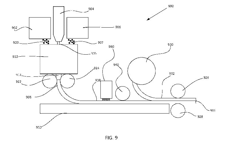
FIG. 9 is a simplified diagram of a system for manufacturing a calendared
sheet good such as
a magnetic or magnetically receptive sheet good according to one embodiment of
the present
invention.
DETAILED DESCRIPTION
The present invention will now be described in more detail with reference to
exemplary
embodiments as shown in the accompanying drawings. While the present invention
is
described herein with reference to the exemplary embodiments, it should be
understood that
the present invention is not limited to such exemplary embodiments. Those
possessing
ordinary skill in the art and having access to the teachings herein will
recognize additional
implementations, modifications, and embodiments, as well as other applications
for use of the
invention, which are fully contemplated herein as within the scope of the
present invention as
disclosed and claimed herein, and with respect to which the present invention
could be of
significant utility.
Magnetized material produces a magnetic field that projects a force that pulls
on or attracts
ferromagnetic or ferrimagnetic materials, e.g., iron, ferrite, strontium
ferrite, barium, nickel,
cobalt, alloys of these and other materials such as rare-earth metals
including neodymium-
based materials. A magnetized component in a surface covering system may be
made using a
magnetic material that is then magnetized, such as by an external magnetic
field applied to it,
e.g., by passing under one or more strong permanent magnets or an
electromagnet, so as to
create a permanent or persistent magnetic field having remanence. Processes
may be
employed to apply a strong magnetic field during manufacture to alter the
atomic structure
and align internal microcrystalline structure resulting in greater remanence
in the absence of
an applied magnetic field. In particular, rare earth materials may be
processed to align
electrons to increase magnetic strength. Depending on the desired result,
multiple stages of
magnetization and magnetic alignment may be performed on a magnetic material.
The
magnetic strength of a magnetized material may be measured in terms of its
magnetization
(often denoted as M in A/m (amperes/meter) as a vector field), magnetic moment
(often
13
CA 03133567 2021-09-14
WO 2020/150719
PCT/US2020/014299
denoted as m or II. in A*m2 as a vector) or magnetic field or flux or flux
density (often
denoted as B in teslas (T ¨ weber/m2) as a vector field). Materials that may
be magnetized are
magnetically receptive and attracted to magnets prior to magnetization.
The strength of a magnet may be expressed in terms of its pull force, i.e.,
the magnet's ability
to move or "pull" magnetically receptive objects. The pull force exerted by a
permanent
magnet is Maxwell's Equation expressed as:
F = B2Al2,uo Eq. 1
where F is force in newtons (SI); A is the cross-section of area in
meters*squared; and B is
the magnetic induction exerted by the magnetized material.
Relatedly, the Maxwell unit of measurement in the CGS (centimeter(cm)-gram-
second)
system is a unit of magnetic flux (4:1)) (which is the integral of field over
an area) and one
Maxwell is the total flux across a surface of one square centimeter
perpendicular to a
magnetic field having a strength of one gauss, i.e., one Maxwell = one gauss x
cm2 ; and one
Maxwell = 10-8 weber (in the SI International System of Units). The gauss (G)
is the CGS
unit of measurement of magnetic flux density or magnetic induction (B) and one
gauss = one
10 tesla. Accordingly, units and expressions may be in either of CGS or
SI and it is
understood for purposes of this invention and the claims both apply equally.
One key consideration when considering effective use of magnetic surface
covering systems
is the applications, e.g., is the covering component being placed opposite an
underlayment on
.. a wall, a floor, a ceiling, a roof, a high-wind area, to meet building
codes or classifications,
etc. For instance, a magnet's holding strength required in the case of a
vertical contact
surface is very different than the holding strength required in the case of a
horizontal contact
surface. An interior horizontal contact surface application, i.e., the contact
surface is
horizontal or parallel to the ground or Earth, has essentially nil shear force
operating against
the system due to gravity. In contrast, a vertical application with the system
perpendicular to
ground has a significant shear force acting due to gravity creating potential
for
disengagement or slipping of the surface cover component against the
underlayment, which
may be fixed in some manner to the vertical wall or other surface.
Accordingly, greater
magnetic strength or pull is required given a vertical contact surface due to
the weight of the
.. covering component being placed and supported by the underlayment. In
addition, in exterior
14
CA 03133567 2021-09-14
WO 2020/150719
PCT/US2020/014299
conditions additional forces act on the system to place even greater burden on
the system and
increase the magnetic strength requirements to maintain system integrity.
System Component Receptive Material or "SCRM" refers to a material and/or
composition
for use manufacturing magnetically receptive layer products "MRLP" and
underlayment
products and may include, for example, a powder-based component or a sheet
product, which
may also be referred to as "Bulk Iron Material." In one implementation, the
SCRM in powder
form may be directly pressed or otherwise applied to receptive layer
components to arrive at
a MRLP. In an alternative implementation, the SCRM may be used to make an
intermediate
sheet good for combining with finished surface cover components to arrive at
MRLP
products, in essence converting a non-magnetically receptive layer product,
e.g., a wall or
floor covering finished product, into an MRLP.
In one manner of implementing aspects of the present invention, modular
surface covering
units comprise a surface covering portion that may be, for example, a
decorative floor or wall
tile, a decorative wood plank, a decorative vinyl plank, or a carpet square.
Other floor
covering unit material types, shapes, and compositions may be used. The
surface covering
unit may a floor, wall or ceiling covering unit or may also be, for example, a
trim or
decorative piece other than a covering unit. In this manner, the floor or
other covering unit
may be used in a "interchangeable box system" wherein all covering units and
decorative
elements in the system may be easily installed, removed, moved, or rearranged
on a magnetic
underlayment disposed on a supporting surface (i.e., wall, floor, ceiling).
Each modular
surface covering unit also comprises a magnetically receptive layer. This
magnetically
receptive layer may be referred to as a "SCRM" layer or a "receptive '13' side
layer." The
SCRM layer (receptive "B" side layer) in the interchangeable box system takes
on many
different forms and processes depending upon the building material and the
material
composition of said building material.
In the present invention, each modular surface covering unit comprises a floor
covering
portion that may be, for example, a decorative floor tile, a decorative wood
plank, a
decorative vinyl plank, or a carpet square. Other floor covering unit material
types, shapes,
and compositions may be used. Additionally, the floor covering unit may
instead be a wall or
ceiling covering unit or may also be, for example, a trim or decorative piece
other than a
covering unit. In this manner, the floor or other covering unit may be used in
a
"interchangeable box system" or "magnetic box system" wherein all covering
units and
CA 03133567 2021-09-14
WO 2020/150719
PCT/US2020/014299
decorative elements in the system may be easily installed, removed, moved, or
rearranged on
a magnetic underlayment disposed on a supporting surface (i.e., wall, floor,
ceiling). Each
modular surface covering unit also comprises a magnetically receptive layer,
which may be
extruded onto the surface covering unit or may be a separate layer affixed to
the unit. This
magnetically receptive layer may be referred to as a system component
receptive material
("SCRM") layer or a "receptive '13' side layer." The SCRM layer (receptive "B"
side layer)
in the interchangeable box system takes on many different forms and processes
depending
upon the building material and the material composition of said building
material.
ISOTROPIC MAGNETICALLY RECEPTIVE AND MAGNETIC LAYERS:
The SCRM receptive layer of a covering unit, such as a modular floor covering
unit, in the
interchangeable box system may be adhered to organic compound materials such
as natural
wood or to natural stone or ceramic stone. The SCRM receptive layer may also
be used with
synthetic building materials such as luxury vinyl tiles "LVT", luxury vinyl
plank "LVP",
rubber compound products like sports surfaces and other similar surface
coverings. Since the
SCRM layer is used with different surface covering material compositions, it
must comprise
certain qualities for all applications. However, different materials and
processes must be used
to manufacture the SCRM layer when it is to be used with surface covering
materials having
"like" properties.
The interchangeable box system ¨ magnetized underlayment, magnetically
receptive layer,
and surface covering unit (e.g., modular floor covering unit) ¨ comprises
unique properties
and qualities that can be utilized to work with existing building materials.
Additionally, other
qualities are desired in the system to be compatible with a wider range of
materials and in a
wider range of applications. These additional qualities include, but are not
limited to
oxidation resistance, dimensional stability (i.e., will not grow or contract
when exposed to
outside/inside elements, for example changes in temperature or humidity),
resistance to harsh
chemicals and solvents (e.g., cleaning products), oils, heat, flammability,
abrasion, rolling
loads, heavy loads, vibration, foot traffic and the like. The elements of the
interchangeable
box system must also be receptive to the "A" side magnetized underlayment
disposed on the
supporting surface which must also comprise equal or similar properties.
In most SCRM applications, wherein the SCRM layer is joined to either natural,
non-natural,
or synthetic building materials, production of the SCRM layer comprises
blending ferrous
16
CA 03133567 2021-09-14
WO 2020/150719
PCT/US2020/014299
compounds with a desired polymer (e.g., Chlorinated Polyethylene "CPE") to
provide the
SCRM layer with the desired properties described hereinabove. Additionally, a
conditioning
agent such as Epoxidized Soybean Oil "EPO" is used to achieve the desired
flexibility and
adherence during manufacture.
A ferrite is a type of ceramic compound composed of iron(III) oxide (Fe2O3)
combined
chemically with one or more additional metallic elements (e.g., iron oxide and
strontium
carbonate stainless iron powder, iron oxide 304 and other metallic compounds).
Ferrite
compounds are electrically nonconductive and ferrimagnetic, meaning they can
be
magnetized or attracted to a magnet. Ferrites can be divided into two families
based on their
magnetic coercivity and their resistance to being demagnetized. Hard ferrites
have high
coercivity and are difficult to demagnetize. They are used to make magnets,
for example in
devices such as refrigerator magnets, loudspeakers and small electric motors.
Hard ferrites
may be used in the production of the "A" side interchangeable box system
magnetic
underlayment. However, other compounds may be used in some applications for
the magnetic
underlayment where other properties are desired. Soft ferrites have low
coercivity.
One embodiment of the interchangeable box system of the present invention uses
a strontium
ferrite compound having a hexagonal crystal structure at a 1.9-2.3 micron size
for the "B"
side receptive layer and the "A" side magnetic underlayment. However, the "A"
side
magnetic underlayment micron size may use an increased individual particle
surface area to
increase potential magnetization. An exemplary strontium ferrite compound may
have the
chemical structure SrFe12019 Sr0.6Fe203. Mesh size of the magnetic components
as
discussed below may be optimized based on application or other requirements.
Ferrites are produced by heating a mixture of finely-powdered precursors
pressed into a
mold. During the heating process, calcination of carbonates occurs in the
following chemical
reaction:
MC03 ¨> MO + CO2
The oxides of barium and strontium are typically supplied as their carbonates,
BaCO3 or
SrCO3. The resulting mixture of oxides undergoes sintering. Sintering is a
high temperature
process similar to the firing of ceramic ware.
17
CA 03133567 2021-09-14
WO 2020/150719
PCT/US2020/014299
Afterwards, the cooled product is milled to particles smaller than 2 p.m,
small enough that
each particle consists of a single magnetic domain. Next the powder is pressed
into a shape,
dried, and re-sintered. The shaping may be performed in an external magnetic
field, in order
to achieve a preferred orientation of the particles (anisotropy). This may be
used to produce
an anisotropic sheet good.
Small and geometrically easy shapes may be produced with dry pressing.
However, in such a
process small particles may agglomerate and lead to poorer magnetic properties
compared to
a wet pressing process. Direct calcination and sintering without re-milling is
possible as well
but leads to poor magnetic properties.
To allow efficient stacking of product in a furnace during sintering and to
prevent parts
sticking together, product may be separated using ceramic powder separator
sheets. These
sheets are available in various materials such as alumina, zirconia and
magnesia. They are
also available in fine, medium and coarse particle sizes. By matching the
material and particle
size to the product being sintered, surface damage and contamination can be
reduced while
maximizing furnace loading.
Chlorinated polyethylene elastomers ("CPE") and resins have excellent physical
and
mechanical properties, such as resistance to oils, temperature, chemicals, and
weather. CPE
polymers, which may be referred to as "marine polymers", may be used to
provide a
waterproof membrane or waterproofing characteristics to a sheet good produced
for the
interchangeable box system (e.g., the receptive "B" layer or the magnetized
underlayment
"A" layer). CPEs may also exhibit the characteristics of superior compression
set resistance,
flame retardancy, tensile strength and abrasion resistance and may provide
these
characteristics to the magnetic underlayment or magnetically receptive layer.
CPE polymers comprise may materials from rigid thermoplastics to flexible
elastomers,
making them highly versatile. CPE polymers are used in a variety of end-use
applications
such as wire and cable jacketing, roofing, automotive and industrial hose and
tubing, molding
and extrusion, and as a base polymer. In a preferred embodiment, a CPE polymer
is the
desired polymer in the magnetically receptive "B" and magnetic underlayment
"A" side
layers of the interchangeable box system of the present invention.
18
CA 03133567 2021-09-14
WO 2020/150719
PCT/US2020/014299
CPE polymers blend well with many types of plastics such as Polyethylene, EVA,
and PVC
which many building materials, such as Luxury Vinyl Plank and Tile Flooring
Products, are
comprised of Such blends of CPE polymers and other plastics can be formed into
final
products with adequate dimensional stability without the need of
vulcanization. The excellent
additive/filler acceptability characteristics of CPE polymers can provide a
benefit in blends
where compound performance and economics are critical such as in the
production of the
magnetically receptive "B" and magnetic underlayment "A" side layers of the
interchangeable box system of the present invention.
Epoxidized soybean oil (ESBO) is a collection of organic compounds obtained
from the
epoxidation of soybean oil. It is used as a plasticizer and stabilizer in
polyvinyl chloride
(PVC) plastics. ESBO is a yellowish viscous liquid. ESBO is manufactured from
soybean oil
through the process of epoxidation. Polyunsaturated vegetable oils are widely
used as
precursors to epoxidized oil products because they have high numbers of carbon-
carbon
double bonds available for epoxidation. The epoxide group is more reactive
than double bond
and thus providing a more energetically favorable site for reaction and making
the oil a good
hydrochloric acid scavenger and plasticizer. Usually a peroxide or a peraclid
is used to add an
atom of oxygen and convert the -C=C- bond to an epoxide group.
Food products that are stored in glass jars are usually sealed with gaskets
made from PVC.
ESBO is typically one of the additives in the PVC gasket in that type of
application. It serves
as a plasticizer and as a scavenger for hydrochloric acid released when the
PVC degrades
thermally, e.g. when the food product undergoes sterilization.
Strontium ferrite, CPE polymers, and ESBO are used in making the magnetized
underlayment "A" and magnetically receptive "B" side layers for the
interchangeable box
system of the present invention. The three compounds, strontium ferrite, CPE
polymer, and
ESBO, are used in various formula compositions and also provide unique
properties that
conventional methods of adherence of building materials simply do not have.
Utilization of
these compounds ensure that no volatile organic compounds "VOCs" are brought
into
building structures ¨ a common problem of conventional adherence systems
(e.g., glue down
applications).
The interchangeable box system of the present invention may use one of the
following
formulas for the composition of the magnetized underlayment "A" and
magnetically
19
CA 03133567 2021-09-14
WO 2020/150719
PCT/US2020/014299
receptive "B" side layers. The specific formula chosen depends on the
supporting surface,
surface covering unit, environmental conditions, and use case for the
interchangeable box
system by the end user. The same formula or "bulk material" may be used for
both layers,
however, a strontium ferrite-based material is desirable for the underlayment
layer and a
ferrous iron-based material is desirable for the magnetically receptive "B"
layer. The ferrous
iron-based material is already at least partially oxidized providing a nearly
rust proof layer.
Additionally, a stainless iron mixture could be used in place of the ferrous
iron-based
material.
For both a strontium ferrite-based underlayment or a ferrous iron-based "B"
layer, the layers
start in a non-magnetized or receptive state. Strontium ferrite is more
suitable for a magnetic
underlayment as the strontium ferrite-based material performs better as a
magnet than as a
receptive layer compared to the ferrous iron-based material. Strontium ferrite
is receptively
weaker than ferrous iron. Ferrous iron (e.g., Fe2O3) is relatively more rust
proof and
magnetically receptive than strontium ferrite. A magnetic underlayment layer
comprising a
strontium ferrite-based material mixture would typically be approximately 1 mm
thick. A
magnetically receptive layer, such as a SCRM material layer, comprising a
ferrous iron-based
material mixture would typically be approximately 0.5 mm thick.
Magnetic or magnetically receptive sheet good material composition formulas
include the
following:
Pure iron powder (Fe) approximately 84%, CPE approximately 15% and soybean oil
(ESBO)
approximately 8%;
Iron powder (Fe304) 90%, CPE 9% and plasticizer 1% (C19H3603 epoxy ester);
Mn-Zn (manganese/zinc) soft ferrite powder 90%, CPE 9% and plasticizer 1%;
20 portions of CPE, 150 portions of stainless iron powder; and
30 portions of PVC, 18 portions of DOTP, 200 portions of stainless iron
powder. (Dioctyl
terephthalate, commonly abbreviated DOTP or DEHT, is an organic compound with
the
formula C6H4 2. It is a non-phthalate plasticizer, being the diester of
terephthalic acid and
the branched-chain 2-ethylhexanol. This colorless viscous liquid may be used
for softening
PVC plastics).
CA 03133567 2021-09-14
WO 2020/150719
PCT/US2020/014299
These formulas are mixed and formed into a sheet good that is either "hot
pressed" into or
onto an existing building material, such as one comprised of synthetic
materials. Natural
materials (e.g., natural wood or natural stone) are "cold pressed" into
natural materials as to
not damage the natural material. The formulas provided above do not comprise
the most
receptive sheet good for a magnetization process. The formulas above each
comprise a
tradeoff to have the required strength to hold a building material in a fixed
position on a plane
(e.g., supporting surface such as a wall or floor), and have the desired
qualities stated above.
Depending upon the nature of the existing building material onto which the
magnetically
receptive "B" layer or the magnetized underlayment "A" layer is to be disposed
different
compositions may be used and are not necessarily limited to one of the
formulas provided
above. However, the above formulas are the preferred formula for most building
material
compositions and installation applications. In addition, depending upon the
material
composition for the surface covering unit onto which the finished sheet good
(e.g., magnetic
underlayment or magnetically receptive layer) is to be applied, the formula
for the sheet good
may be changed. For example, the formula may comprise mixing different
powders,
plasticizers, and other materials for the composition of the sheet good used
in the magnetic
underlayment or magnetically receptive layer. Compounds that are not as
receptively strong,
but that have already been oxidized, such as ferrous oxide or stainless iron
powder, are used
so that the sheet good is highly resistant to rust.
Exemplary processes for producing the sheet good for the magnetically
receptive "B" layer or
the magnetic underlayment "A" are provided in FIGs. 1 and 2. With reference
first to FIG. 1,
a process 100 for producing the sheet good at atmospheric pressure is
provided. First, the
components for producing the sheet good, such as strontium ferrite, CPE
polymer, ESBO,
according to the desired formula are placed in a mixer in step 102. Then in
step 104, the
materials are mixed and blended in a mixer, such as a banbury mixer, for
approximately
around 15 minutes at a maximum temperature is 120 C. The mixed materials are
then
compressed and extruded in step 106 as a sheet at a rate of approximately 10m
per minute at
a temperature of approximately 80 C. In all steps of the process 100, the
mixture is exposed
to the air at atmospheric pressure and not in a vacuum or partial vacuum. An
additional
annealing process 408 may be performed after the mixture has been extruded as
a sheet good.
CPE polymers have properties that are better for dimensional stability than
other possible
materials but may still have dimensional stability issues. For formulas
incorporating CPE
21
CA 03133567 2021-09-14
WO 2020/150719
PCT/US2020/014299
polymers the step 108 of annealing will be used, but is not required in all
sheet good
formulas. In another embodiment, a CPE polymer having a higher melting point
may be used.
A blend or mixture using a higher melting point CPE polymer may require a
different binder
than a lower melting point CPE polymer. A blend using a high melting point CPE
polymer
may be mixed at approximately 190 C and may also require higher temperatures
at the
extrusion and compression stages of forming the sheet good.
This vulcanizing/annealing step 108 is performed before the sheet good is
applied to a
building material to be used as the surface covering unit. A test of the sheet
good may be
performed at the lab level to determine the dimensional stability of the sheet
good. For the
sheet good to be used in securing a surface covering unit a desired level of
dimensional
stability is required. If the sheet good used as a magnetic underlayment "A"
layer or
magnetically receptive "B" layer is not dimensionally stable the surface
covering unit may
not stay installed as desired and the system may fail. For example, in the
case of a flooring
material, the flooring may have a catastrophic failure due to expansion and
contraction and
"warp" the building material causing or "peaks" or "gaps" which are not
desirable and would
lead and imperfect installation.
Annealing is a heat treatment that alters the physical and sometimes chemical
properties of a
material to increase its ductility and reduce its hardness. In annealing,
atoms migrate in the
crystal lattice and the number of dislocations decreases, leading to the
change in ductility and
hardness. This process makes it more workable. Annealing is used to bring a
metal closer to
its equilibrium state. In its heated, soft state, the uniform microstructure
of a metal will allow
for excellent ductility and workability. In order to perform a full anneal in
ferrous metals the
material must be heated above its upper critical temperature long enough to
fully transform
the microstructure to austenite. The metal must then be slow-cooled, usually
by allowing it to
cool in the furnace, so as to allow maximum ferrite and pearlite phase
transformation.
Table 1 and Table 2, provided below illustrate the dimensional change, in the
length direction
in Table 1 and in the width direction in Table 2, of a sheet good after a 71
hour annealing
process.
Length Direction
22
CA 03133567 2021-09-14
WO 2020/150719
PCT/US2020/014299
Length L. after L. Change L. Change
(mm) (mm) (mm) %
229.16 229.04 -0.12 -0.05
209.71 209.51 -0.20 -0.10
189.44 189.22 -0.22 -0.12
Receptive 129.47 129.35 -0.12 -0.09
Layer, 130.04 130.03 -0.01 -0.01
128.29 128.29 0.00 0.00
55 C,
238.97 238.95 -0.02 -0.01
71 hrs. 238.84 238.60 -0.24 -0.10
238.84 238.75 -0.09 -0.04
3400.00 3400.00 0.00 0.00
2158.00 2156.00 -2.00 -0.09
261.46 261.40 -0.06 -0.02
Magnetic 260.85 260.67 -0.18 -0.07
Underlayment, 234.63 234.51 -0.12 -0.05
240.37 240.34 -0.03 -0.01
55 C,
231.07 230.95 -0.12 -0.05
71 hrs. 2372.80 2370.00 -2.80 -0.12
2366.00 2366.00 0.00 0.00
Table 1
Width Direction
Width W. after W. Change W. Change
(mm) (mm) (mm) %
215.33 215.23 -0.10 -0.05
Receptive
239.95 239.88 -0.07 -0.03
Layer,
/ / / /
55 C, 110.99 110.95 -0.04 -0.04
111.45 111.45 0.00 0.00
23
CA 03133567 2021-09-14
WO 2020/150719
PCT/US2020/014299
71 hrs. 113.13 113.11 -0.02 -0.02
238.93 238.73 -0.20 -0.08
239.59 239.52 -0.07 -0Ø3
239.70 239.62 -0.08 -0.03
915.10 915.00 -0.10 -0.01
913.10 912.60 -0.50 -0.05
259.49 259.40 -0.09 -0.03
Magnetic 259.10 259.09 -0.01 0.00
Underlayment, 239.77 239.71 -0.06 -0.03
204.79 204.68 -0.11 -0.05
55 C,
259.88 259.82 -0.06 -0.02
71 hrs. 791.90 790.70 -1.20 -0.15
792.00 791.10 -0.90 -0.11
Table 2
After the annealing step 108, or if the annealing step 108 is not required due
to the formula
composition used for the sheet good, the sheet good is then be hot pressed
onto a synthetic
building material product in step 110 or cold pressed into a natural building
material product
in step 120 to form a finished surface covering unit. If the sheet good is not
to be used on a
surface covering unit and is to be used as a magnetic underlayment, a
magnetization step may
be performed on the sheet good to form a magnetic underlayment "A" layer.
To magnetize the underlayment "A" layer a magnetic roller may be used. The
magnetic roller
comprises a plurality of north and south poles positioned very closely to one
another on the
roller. For thicker underlayments, where a large number of north/south poles
are not required
for achieving a desired magnetic remanence in the material, the north/south
poles may be
relatively spaced out on the roller. In this application, a roller comprising
a plurality of
magnetic washers compressed together on a rod or axle may be used. Exemplary
systems are
described in U.S. Pat. Pub. 2008/0278272, entitled SHEET MAGNETIZER SYSTEMS
AND
METHODS THEREOF, filed April 15, 2008, Arnold; and in U.S. Pat. 7,728,706,
entitled
MATERIAL MAGNETIZER SYSTEMS, issued June 1, 2010. Reducing the distance
between the north and south poles on the roller provides for more north/south
poles to be
magnetized on the magnetic underlayment "A" layer, thereby producing a
magnetic
24
CA 03133567 2021-09-14
WO 2020/150719
PCT/US2020/014299
underlayment with a greater magnetic remanence. This is required for producing
a thinner
magnetic underlayment with the same or greater magnetic remanence than a
thicker layer. To
magnetize a thinner magnetic underlayment "A" layer with a roller, a solid
roller must be
used. The solid roller may be comprised of a ferrite material or of neodymium
metal.
A solid magnetic roller comprises a plurality of north/south poles etched or
engraved onto the
roller. The etched or engraved roller is magnetized in a pulse magnetizer
which may
comprise a magnetic coil and an aligning field. The field in the pulse
magnetizer may be
configured to cause the particles in the roller to point in a particular
direction. The etched
roller may have etched and pulse-magnetized poles positioned between 1 and 2
mm apart,
with closer poles being required for thinner magnetic underlayments. Another
embodiment
may employ a solid roller without any etching and wherein the underlayment
layer to be
magnetized comprises the etched north/south poles. This provides for even
closer north/south
poles than with an etched roller. The laser etching may be performed using
prisms and gyro-
moved laser diodes. The use of gyro-moved lasers maximizes the number of poles
that can be
transferred or etched onto a hot, compressed, underlayment layer.
With reference now to FIG. 2, a process 200 for producing a sheet good at non-
atmospheric
pressure is provided. First, the components for producing the sheet good, such
as strontium
ferrite, CPE polymer, ESBO, according to the desired formula are placed in a
mixer in step
202. Then in step 204, the materials are mixed and blended in a mixer, such as
a banbury
mixer, for 20-30 minutes at a temperature of 90-115 C and at a pressure of 0.4-
0.7MPa. In
step 206 the sheet good is extruded at a compression rate into sheet form at a
rotation rate of
4.0-10 meters per minute and at a temperature of 40-70 C. The mixture is
compressed into a
sheet good in step 206 by mutually compacting two rollers into a specified
thickness which is
typically 0.3mm in thickness for a magnetically receptive "B" layer. An
additional annealing
process 208 may be performed after the mixture has been extruded as a sheet
good. For
formulas incorporating CPE polymers the step 208 of annealing will be used,
but is not
required in all sheet good formulas. After the annealing step 208, or if the
annealing step 208
is not required due to the formula composition used for the sheet good, the
sheet good is then
be hot pressed onto a synthetic building material product in step 210 or cold
pressed into a
natural building material product in step 220 to form a finished surface
covering unit. If the
sheet good is not to be used on a surface covering unit and is to be used as a
magnetic
CA 03133567 2021-09-14
WO 2020/150719
PCT/US2020/014299
underlayment, a magnetization step may be performed on the sheet good to form
a magnetic
underlayment "A" layer.
For both the process 100 in FIG. 1 and the process 200 in FIG. 2, the micron
size of the
strontium ferrite compound is approximately 38-62 microns. This size is the
preferred micron
size in all formulae for the magnetic underlayment "A" layer and magnetically
receptive "B"
layer.
With reference now to FIG. 3, a process 300 for producing a magnetized or
magnetically
receptive material for use in a backing material layer is provided. For some
building
materials, such as with carpet tile, the magnetically receptive "B" layer of
the interchangeable
box system is not made into a sheet good, but is blended directly into the
backing system that
makes up a building material that uses like polymers. An example of one such
formula that
may be incorporated into a PVC backing carpet tile is 16.5% PVC, 39% calcium
carbonate,
26.5% iron powder (Fe304), 16% plasticizer DOP (Bis2-Ethylhexyl Phthalate), or
DINP
(Diisononyl Phthalate), and 2% viscosity depressant & stabilizer. In this
process, materials to
produce the magnetized or magnetically receptive material for use in a backing
material layer
are introduced into a mixer in step 302. The materials are then mixed in a
manner such as is
described in step 104 in FIG. 1, or step 204 in FIG. 2. The mixed material is
then blended
into a backing of a surface covering unit in step 306 to produce a finished
surface covering
unit having a magnetized or magnetically receptive backing layer.
For the processes shown in FIG. 1, FIG. 2, and FIG. 3, a manufacturing system
900 such as is
shown in FIG. 9 may be used. The manufacturing system 900 shown in FIG. 9
provides a
system for producing either a magnetically receptive layer or a magnetized
layer. Some
elements of the system may be used for producing one type of sheet good while
others may
be not be used. In the exemplary embodiment shown in the system 900 in FIG. 9,
the system
900 comprises material storage hoppers 902, 904, and 906, mixer 910, first set
of rollers 922
and 924, conveyor 950, magnetizing roller 940, an annealing oven 960 and a
second set of
rollers 926. The materials 903, 905, and 907 stored in the respective storage
hoppers 904,
906, and 908 may be, for example, a strontium ferrite blend, a CPE polymer,
and ESBO, or
may be more generally a magnetically receptive material blend, a binder or
polymer, and a
plasticizer. Other materials may be stored in other hoppers or storage tanks
as necessary and
as described herein. The materials 903, 905, and 907 are mixed in the mixer
910, which may
be a banbury mixer, at a desired temperature and pressure for a specified
period of time, and
26
CA 03133567 2021-09-14
WO 2020/150719
PCT/US2020/014299
are then extruded through the nozzle 912 through the first set of rollers 922
and 924 into a
calendared sheet good 908. Additional sets of rollers beyond the first set of
rollers 922 and
924 may also be used. A conveyor 950 may the calendared sheet good 908 through
an
annealing oven 960 and through a magnetic roller 940. Where a magnetically
receptive sheet
good is being produced, the magnetic roller 940 will not be used. A pulse
magnetizer or other
magnetization method may be used in place of the magnetic roller 940. The
annealing oven
960 may be any oven or heating source suitable for annealing the calendared
sheet good 908.
After the calendared sheet good 908 has been annealed and magnetized, a
surface covering
932 may be unrolled from a roll 930 and either hot or cold pressed onto the
calendared sheet
good 908 by the second set of rollers 926 and 928 to form the finished surface
covering 901.
Where a magnetic underlayment is being produced this finishing step will not
be performed.
Other materials may also be pressed onto the calendared sheet good 908 other
than a material
unrolled from a roll 930. For example, a magnetically receptive layer
calendared sheet good
908 may be cut-to-size and individually pressed onto surface covering units
not suitable for
being stored in a roll form.
In another embodiment, the present invention provides a method for producing a
magnetically receptive sheet good for use in surface covering systems, the
method
comprising: combining a ferrite compound, a polymer, and a plasticizer in a
mixing vessel;
mixing the ferrite compound, the polymer, and the plasticizer at a desired
mixing temperature
and at a desired mixing pressure to form a magnetically receptive material;
and extruding the
magnetically receptive material at a desired extrusion temperature to form a
magnetically
receptive sheet good; or applying a calendaring process to the magnetically
receptive layer to
form a magnetically receptive sheet good.
The method of the above embodiment may further comprise annealing the
magnetically
receptive sheet good. The method may further comprise cold pressing the
magnetically
receptive sheet good onto a natural material building product. The method may
further
comprise hot pressing the magnetically receptive sheet good onto a synthetic
material
building product. The method may further comprise magnetizing the magnetically
receptive
sheet good. The magnetically receptive layer may be magnetized to produce a
magnetized
underlayment adapted to magnetically engage and support a non-magnetized
receptive layer
component, the composition of the magnetically receptive material is selected
from the group
consisting of: for use in a calendaring process: 1) pure iron powder (Fe) or
strontium ferrite
27
CA 03133567 2021-09-14
WO 2020/150719
PCT/US2020/014299
approximately 89-91%, chlorinated polyethylene elastomer polymer (CPE)
approximately 8-
9% and epoxidized soybean oil (ESBO) approximately 1-2%; or 2) Iron powder
(ferrous iron
or ferrous ferric oxide, Fe304) approximately 89-91%, CPE approximately 8-9%
and
plasticizer approximately 1-2%; or for use in an extrusion process: 3) PVC
approximately
16.5%, calcium carbonate approximately 39%, iron powder approximately 26.5%,
plasticizer
approximately 16%, and viscosity depressant & stabilizer approximately 2%. The
magnetically receptive material may be used to produce a non-magnetized
receptive
component for use opposite a magnetized underlayment component, the
composition of the
magnetically receptive material is selected from the group consisting of: for
use in a
calendaring process: 1) Mn-Zn (manganese/zinc) soft ferrite powder
approximately 89-91%,
CPE approximately 8-9% and plasticizer approximately 1-2%; 2) approximately 20
portions
of CPE, approximately 150 portions of stainless iron powder, approximately 30
portions of
polyvinyl chloride (PVC), approximately 18 portions of dioctyl terephthalate,
approximately
200 portions of stainless iron powder; or for use in an extrusion process: 3)
PVC
approximately 16.5%, calcium carbonate approximately 39%, plasticizer
approximately 16%,
viscosity depressant & stabilizer approximately 2%, and at approximately 26.5%
one of: Mn-
Zn (manganese/zinc) soft ferrite powder; stainless iron powder; or ferrous
oxide or ferric
oxide powder. The ferrite compound may be strontium ferrite, the polymer is
chlorinated
polyethylene elastomer polymer (CPE), and the plasticizer is epoxidized
soybean oil (ESBO).
The mixing may be performed for approximately 15 minutes, the desired mixing
temperature
may be under 120 degrees Celsius, and the desired mixing pressure is
atmospheric pressure.
The desired extrusion temperature may be 120 degrees Celsius and the
magnetically receptive
sheet good may be extruded at 10 meters per minute. The mixing may be
performed for 20-
minutes, the desired mixing temperature may be between 90-115 degrees Celsius,
and the
25 desired mixing pressure may be between 0.4-0.7MPa. The magnetically
receptive sheet good
may be extruded at 4-10 meters per minute and the desired extrusion
temperature is 40-70
degrees Celsius. The ferrite compound may be strontium ferrite having a
particle size of 38-
62 microns.
In another embodiment, the present invention provides a rust resistant and
dimensionally
30 stable magnetically receptive sheet good for use in surface covering
systems, the sheet good
being magnetized to provide a magnetized underlayment for magnetically
engaging a non-
magnetized receptive layer component, the magnetized underlayment comprising:
for use in a
calendaring process: 1) pure iron powder (Fe) or strontium ferrite
approximately 89-91%,
28
CA 03133567 2021-09-14
WO 2020/150719
PCT/US2020/014299
chlorinated polyethylene elastomer polymer (CPE) approximately 8-9% and
epoxidized
soybean oil (ESBO) approximately 1-2%; or 2) Iron powder (ferrous iron or
ferrous ferric
oxide, Fe304) approximately 89-91%, CPE approximately 8-9% and plasticizer
approximately 1-2%; or for use in an extrusion process: 3) PVC approximately
16.5%,
calcium carbonate approximately 39%, iron powder approximately 26.5%,
plasticizer
approximately 16%, and viscosity depressant & stabilizer approximately 2%. The
ferrite
component may comprise a particle size of 38-62 microns.
In another embodiment the present invention provides a rust resistant and
dimensionally
stable magnetically receptive component for use in surface covering systems,
the
magnetically receptive component being a non-magnetized receptive layer
component for
magnetically engaging with a magnetized underlayment, the magnetically
receptive
component comprising: for use in a calendaring process: 1) Mn-Zn
(manganese/zinc) soft
ferrite powder approximately 89-91%, CPE approximately 8-9% and plasticizer
approximately 1-2%; 2) approximately 20 portions of CPE, approximately 150
portions of
stainless iron powder, approximately 30 portions of polyvinyl chloride (PVC),
approximately
18 portions of dioctyl terephthalate, approximately 200 portions of stainless
iron powder; or
for use in an extrusion process: 3) PVC approximately 16.5%, calcium carbonate
approximately 39%, plasticizer approximately 16%, viscosity depressant &
stabilizer
approximately 2%, and at approximately 26.5% one of: Mn-Zn (manganese/zinc)
soft ferrite
powder; stainless iron powder; or ferrous oxide or ferric oxide powder.
ANISOTROPIC MAGNETIC AND MAGNETICALLY RECEPTIVE LAYERS:
The magnetic and magnetically receptive layers described above for use in the
magnetic box
system are isotropic or "non-directional." For an isotropic magnetic layer,
there is no aligning
field used in the magnetization process. This means that the underlayment and
receptive
layers may be installed on a surface in a direction independent manner. In
some
implementations of the magnetic box system, an anisotropic magnetic or
magnetically
receptive sheet good is desired. In an anisotropic layer an aligning field is
used in the
magnetization process to align all particles in the magnetic underlayment "A"
layer in the
same direction. For example, a thinner sheet good with a stronger magnetic
bond may be
desirable in installations where weight, but not directionality of
installation, is a concern.
29
CA 03133567 2021-09-14
WO 2020/150719
PCT/US2020/014299
Aviation, or installing surface covering units on the floors, fuselage
interior, bulkheads, and
other interior surfaces of an airplane, is one application that is
particularly sensitive to the
weight of materials used. The use of an anisotropic blend is desirable in an
aviation
application due to weight concerns on aircraft. A different material component
blend is used
for an anisotropic layer than is used with the isotropic magnetic and
magnetically receptive
layers described above, but a similar or greater magnetic strength using
anisotropic powders
is achieved. Additionally, the layer thickness for the anisotropic layer has
been reduced from
1.0mm to 0.5mm compared to the ferrous iron or strontium ferrite isotropic
layers. Reducing
the thickness by at least 50% compared to the isotropic layers provides a
weight savings of
nearly the same amount in an anisotropic layer having a similar magnetic
remanence.
With reference to FIG. 4, an exemplary interchangeable box system 400
comprising an
isotropic surface covering unit 410 and a supporting surface assembly 401 with
an
anisotropic magnetic underlayment 402 with a 0.5 mm thickness disposed on a
supporting
surface 404 according to the present invention is provided. The isotropic
surface covering
unit 410 comprises a decorative or top layer 412 and an isotropic magnetically
receptive
SCRM "B" side layer 414. The isotropic magnetically receptive layer 414 is
magnetically
attracted to the anisotropic magnetic underlayment 402 disposed on a
supporting surface 404.
Existing isotropic underlayments may have a thickness of 1.52 mm. However, for
both
isotropic and anisotropic underlayments reducing the Mesh size, thereby
lowering the micron
size of the particles in the material blend used to produce the magnetic
layer, increases the
surface area of each individual particle. This produces a higher magnetic
strength due to an
increased surface area per particle because of the particular crystal
structures of the smaller
particles. This in turn provides for a reduced thickness and overall raw
material use in the
magnetic underlayment.
A reduced Mesh size for the raw materials used in producing the magnetically
receptive layer
and magnetized underlayment provides for thinner layers. For example, using a
smaller Mesh
size provides for a magnetic underlayment with a 1.0 mm thickness to be used
on a horizontal
plane supporting surface (e.g., floor coverings) and a 0.5 mm thickness on
vertical plane
supporting surfaces (e.g., wall coverings). The smaller Mesh size provides
benefits to
magnetically receptive layers and magnetic underlayments comprising blends of
anisotropic
and isotropic materials, only anisotropic materials, or only smaller Mesh size
isotropic
materials. The thickness of the magnetically receptive or magnetic
underlayments are may be
CA 03133567 2021-09-14
WO 2020/150719
PCT/US2020/014299
within +/- 0.5 mm of the ideal layer thickness depending on the particular
installation
application for which the layer will be used and depending on how the layer
will be installed
or secured to a surface.
Properties for both an isotropic magnetic underlayment layer and an
anisotropic magnetic
.. underlayment layer having a Mesh size of 1-2.3 p.m for one or more of
ferrite powders, iron
powders, and anisotropic powders are provided in Table 3 and Table 4, below.
Isotropic Magnetic Underlayment
Thickness ¨1.0mm
Hardness Shore 52-56
Surface Magnetic Strength > 410 Gauss
Pull Strength > 39 g/cm2
Vertical and Horizonal Sheer Strength > 12 N
Table 3
Anisotropic Magnetic Underlayment
Thickness ¨0.5 mm
Hardness Shore 52-56
Surface Magnetic Strength > 360 Gauss
Pull Strength > 24 g/cm2
Vertical and Horizonal Sheer Strength > 9 N
Table 4
Although anisotropic means that the magnetic underlayment is "oriented" in one
direction
(whereas isotropic is not), the magnetically receptive material is isotropic.
Using an
anisotropic magnetic "A" layer and an isotropic magnetically receptive "B"
layer and
provides for the entire system to still be isotropic, or directionless, in
nature (i.e., no fixed
installation orientation for surface covering units having an isotropic
magnetically receptive
layer on an anisotropic magnetic underlayment layer). Two exemplary formulas
for
producing magnetic underlayment layers are provided in Table 5 and Table 6,
below.
Formula 1
Ferrite powder (e.g., Fe304) 87%
31
CA 03133567 2021-09-14
WO 2020/150719
PCT/US2020/014299
CPE (thermoplastic chlorinated 12%
polyethylene elastomer, which is
produced by chlorination of
polyethylene)
Epoxidized soybean oil ("ESBO") 0.8%
Table 5
Formula 2
Ferrite powder (e.g., Fe304) 89%
CPE and PVC Blend 9%
Plasticizer 0.5%
ESBO 1.5%
Table 6
In Formula 1, the ESBO is a collection of organic compounds obtained from the
epoxidation
of soybean oil. It is used as a plasticizer and stabilizer in polyvinyl
chloride plastics. ESBO is
.. a yellowish viscous liquid. For both formulas, the magnetic underlayment is
calendared into a
sheet good without the use of a fiberglass scrim layer. The mixture is first
mixed and blended
in a banbury mixer for 25-35 minutes, temperature: 120-135 C, pressure: 0.4-
0.7MPa. The
sheet good is formed by compressing the mixture into a sheet at a rotation
rate of 4.0-10 rpm
at a temperature of 40-80 C. The mixture is compressed into sheet form by
mutually
compacting two rollers for the specified thickness and then is put into a
series of shaping
rollers to fine tune the exact thickness of the underlayment sheet to a
desired thickness. A
final UV (ultraviolet) oil coating may then be applied on a conveyor belt
through a spray mist
and baked to set under an Ultraviolet light. The UV oil is sensitive and
reactive to the UV
light. In this manner the coating has the desired benefit of setting very
quickly (rapid set) and
optimally sets at the normal manufacturing line speed, i.e., the operator does
not have to slow
the line speed to allow extended baking or heating for setting purposes. This
rapid set feature
can be included in either an extrusion process or a calendaring process and
for use in setting a
layer as an underlayment or in connection with fabricating surface covering
components. In
connection with underlayment fabrication, the sheet of magnetic underlayment
is then rolled
onto a spool and cut into the desired roll length.
In another embodiment, the present invention provides a system of surface
covering
components, the system when installed providing a quasi-permanent surface
covering, the
32
CA 03133567 2021-09-14
WO 2020/150719
PCT/US2020/014299
system comprising: a surface covering unit comprising an isotropic
magnetically receptive
layer; and an anisotropic magnetic underlayment disposed on a supporting
surface.
The target thickness for an anisotropic magnetic underlayment may be 0.5 mm in
thickness,
e.g., in applications requiring low profile (thickness) and low weight such as
interior surface
covering for airplanes. The anisotropic magnetic underlayment may further
comprise: a
magnetizable material; a binder; and an oil. The magnetizable material may
comprise one of:
ferrous iron powder, strontium ferrite powder, neodymium powder, and a
neodymium and
ferrous iron composite. The binder may comprise thermoplastic chlorinated
polyethylene
elastomer ("CPE"). The oil may comprise epoxidized soybean oil ("ESBO"). The
anisotropic
magnetic underlayment may be a calendared sheet good. A desired thickness may
be a
function of composition of materials included in the extrusion or blending
processes (such as
a choice of the exemplary formulations set forth herein), extrusion spraying
techniques,
calendaring techniques, target weight, desired magnetic strength, magnetic
receptivity or
attraction of the intended surface component, wall vs. floor applications, and
building code
requirements, to name a few considerations. The anisotropic magnetic
underlayment may
further comprise a magnetizable material having a Mesh size of 1-2.3 p.m.
NEODYMIUM MAGNETIC LAYER:
In another embodiment, a magnetic underlayment may be produced using a blend
of
neodymium and ferrite powder. An approximately 50/50 blend of neodymium powder
and
ferrite powder can be used to produce an anisotropic and isotropic sheet for
interior or
exterior use (e.g., roofs and exterior finishing). This "hybrid" blend of
neodymium powder
and ferrite powder provides an average of eight times increase in potential
magnetic hold
over a ferrite powder but at an increased cost. A magnetic underlayment
comprising a blend
of neodymium and ferrite powder would be suitable for applications such as
roofs, extra
heavy cladding on exteriors, slab stone, where an increase magnetic remanence
over ferrite
powder would be required.
Neodymium is an element of the rare earth family of metals. It has the atomic
symbol Nd,
atomic number 60, and atomic weight 144.24 g/mol. Neodymium is not found
naturally in
metallic form or unmixed with other lanthanides, and it is usually refined for
general use.
Although neodymium is classed as a "rare earth", it is no rarer than cobalt,
nickel, and copper
ore, and is widely distributed in the Earth's crust, but mostly mined in
China. A "hybrid"
33
CA 03133567 2021-09-14
WO 2020/150719
PCT/US2020/014299
magnetic underlayment "A" layer comprising a neodymium and ferrite powder
blend can
support a significantly greater hanging weight than a ferrite powder magnetic
underlayment.
The "hybrid" magnetic underlayment "A" layer comprising a neodymium and
ferrite powder
blend is well suited for use as a complete roofing underlayment capable of
withstanding
hurricane or tornado force winds. Additionally, it may be used as the
fastening system for
glass solar panels reducing the cost of installing solar panels as a
significant portion of the
expense in installing solar panels is the fastening system and labor to
install them.
Neodymium powder blends and "hybrid" magnetic underlayment are also suited to
installation applications where weight is a concern. Because a "hybrid"
magnetic
.. underlayment has a relatively stronger pull than a ferrous iron or
strontium ferrite blended
underlayment, a thinner layer may be used to achieve the same pull strength.
This may be
desirable in installation applications in aircraft and in vehicles where the
weight of the
material may be a concern.
The blend of neodymium with other materials in the "hybrid" magnetic
underlayment may be
from 50-90% neodymium powder. For example, a composition having 91% neodymium-
based material in an underlayment having a thickness of 0.5mm will provide on
the order of a
20-fold improvement in magnetic attraction or strength over a 1 mm thick
underlayment
using non-neodymium ferrite materials. However, increasing the percentage of
neodymium
powder in the blend is undesirable as it may lead to cracking or crumbling of
"hybrid"
magnetic underlayment as in insufficient percentage of binding material will
be present.
Accordingly, the invention provides alternative formulations to balance
performance
characteristics against application requirements. For example, for every 10%
decrease in
neodymium concentrations, i.e., 91% to 81% to 71%, etc., there is a
corresponding drop in
magnetic strength on the order of 2x, i.e., at 81% the underlayment will be 18-
fold stronger
that a 1 mm non-neodymium-based underlayment, at 71% the underlayment will be
16-fold
stronger that a 1 mm non-neodymium-based underlayment, at 61% the underlayment
will be
14-fold stronger that a 1 mm non-neodymium-based underlayment, etc.
Accordingly, the
ratio of the neodymium powder to the binder, the oil, and/or other materials
may be selected
based upon application considerations to be one of: about 91% neodymium powder
to about
9% binder and oil; about 81% neodymium powder to about 19% binder and oil;
about 71%
neodymium powder to about 29% binder and oil; about 61% neodymium powder to
about
39% binder and oil; or about 51% neodymium powder to about 49% binder and oil.
The
34
CA 03133567 2021-09-14
WO 2020/150719
PCT/US2020/014299
techniques described herein minimize the issue of cracking or brittleness
associated with use
of neodymium-based materials.
With reference to FIG. 5, an exemplary interchangeable box system 500
comprising a surface
covering unit 510 and a supporting surface assembly 501 with a neodymium and
ferrite blend
"hybrid" magnetic underlayment 502 disposed on a supporting surface 504
according to the
present invention is provided. The surface covering unit 510 comprises a
decorative or top
layer 512 and a magnetically receptive SCRM "B" side layer 514. The
magnetically receptive
layer 514 is magnetically attracted to the neodymium and ferrite blend
"hybrid" magnetic
underlayment 502 disposed on a supporting surface 504.
In another embodiment, the present invention provides a magnetic underlayment
layer for
securing magnetically-receptive surface covering units on a supporting
surface, the magnetic
underlayment layer comprising: a neodymium powder; a binder; and an oil.
The magnetic underlayment layer may further comprise a plasticizer. The oil
may comprise
epoxidized soybean oil ("ESBO"). The ratio of the neodymium powder to the
binder and the
oil is less than 91% neodymium powder to 9% binder and oil. The magnetic
underlayment
layer may further comprise a ferrite powder. The ratio of the ferrite powder
to the
neodymium powder may be 50/50.
ULTRAVIOLET CURED OIL-BASED MAGNETIC AND MAGNETICALLY
RECEPTIVE LAYERS:
As described hereinabove, the magnetically receptive, or SCRM layer, is the
"B" side layer
of the Interchangeable Box System (IBS). The SCRM layer may take the form of a
sheet
good that is applied as the last layer in a building material, for example,
the raw materials that
comprise the sheet good may be calendared and then hot pressed, or cold
pressed with resin
glues as the last layer of a building material. In another embodiment, the
materials that
comprise the SCRM "B" layer may be applied to a surface covering using oils
and polymer-
based resin/glues and infused with ferrite powders.
However, these existing methods for applying the SCRM "B" side magnetically
receptive
layer to a surface covering may be cost or weight prohibitive for certain
applications. The
SCRM layer may be applied to a surface covering while reducing cost and
thickness to meet
CA 03133567 2021-09-14
WO 2020/150719
PCT/US2020/014299
this need using ultraviolet ("UV") oil. UV oil is a material commonly used by
surface
covering unit manufacturers as a final protective layer for the surface
covering. For example,
a surface covering unit may comprise a wear layer (i.e., a scratch resistant
coating) that is put
on the surface covering unit as a top layer as a finish spray. The UV oil is
sprayed on to the
top layer of the flooring/wall unit by a set of nozzles. The sprayed surface
covering unit is
then carried away on the assembly belt and is subjected to ultra-high
intensity UV lights that
bake the UV oil to set it and permanently bond the UV oil spray application to
the top layer
as a wear layer.
With reference to FIG. 6, a flowchart of a process 600 for producing a UV oil-
based
magnetically receptive layer is provided. At step 602, the ferrite powder
and/or SCRM
material blend of the present invention and a UV oil are added to a mixer. In
step 604 the
ferrite powder and/or SCRM material blend of the present invention and the UV
oil are
mixed together. In step 606, the blended mixture of the ferrite powder and/or
SCRM material
blend and UV oil are sprayed onto the last or bottom layer of the surface
covering unit
utilizing the same industrial process used to produce the wear layer. The
surface covering
unit with the ferrite infused UV oil is then carried on the assembly belt to
the ultra-high
intensity UV lights in step 608 where the UV oil is permanently bonded/baked
onto the
bottom of the surface covering unit as a completed SCRM "B" side magnetically
receptive
layer. The UV oil magnetically receptive layer may be less than 0.15 mm in
thickness, which
is thinner than the thinnest possible calendared or extruded magnetically
receptive sheet
good.
A PVC based resin may also be used in place of the UV oil. For example, the
ferrite powder
or SCRM material blend may be mixed into the PVC resin, which is then sprayed
on and then
baked in a line oven at a high temperature on the assembly belt to bond the
ferrite powder
infused PVC resin onto the bottom of the surface covering unit as a completed
SCRM "B"
side magnetically receptive layer. The temperature required to set the PVC
resin depends on
the type of PVC resin used.
Other polymers, resins, oils, other suitable liquids, and other suitable semi-
solid material may
be sprayed onto a surface covering unit to form a SCRM layer with an
acceptable hold/sheer
strength. The UV oil sprayed coating does not have to be as thick as the
rolled sheet good
layer and may be 0.1 mm instead of 0.3-0.5 mm thick. The hold strength of a UV
oil sprayed
on SCRM layer is lower than that of a magnetically receptive sheet good but
still sufficient to
36
CA 03133567 2021-09-14
WO 2020/150719
PCT/US2020/014299
secure the surface covering unit in place. The substantially reduced cost of
spraying on a UV
oil based SCRM "B" side magnetically receptive layer provides for the SCRM
layer to be
built into every surface covering unit whether the surface covering unit is to
be installed in a
glue down or magnetically secured installation.
In another embodiment, the present invention provides a method for applying a
magnetically
receptive layer on a surface covering unit, the method comprising: adding a
receptive
material blend and an oil compound in a mixer; blending the receptive material
blend and the
oil compound to form a magnetically receptive oil blend; spraying the
magnetically receptive
oil blend onto a surface covering unit; and setting the magnetically receptive
oil blend onto
the surface covering unit.
The method may further comprise wherein the receptive material blend comprises
one of:
ferrous iron powder, strontium ferrite powder, neodymium powder, and a
neodymium and
ferrous iron powder composite. The method may further comprise wherein the oil
compound
comprises one of: ultraviolet ("UV") oil, and polyvinyl chloride ("PVC")
resin. The setting of
the magnetically receptive oil blend may further comprise setting the
magnetically receptive
oil blend by high intensity ultraviolet ("UV") lights. The setting of the
magnetically receptive
oil blend may further comprise setting the magnetically receptive oil blend by
high
temperature.
MAGNETIC BOX SYSTEM:
.. With reference now to FIG. 7, a simplified perspective diagram of a surface
covering
assembly 700 of a modular surface covering unit 710 with a magnetically
receptive layer 720
and a magnetic underlayment 730 disposed on a supporting surface 750 is
provided. The
modular surface covering unit 710 may be, for example, a floor covering unit
such as a LVT,
stone tile, or a carpet tile. In another embodiment, the surface covering unit
710 may be a
rolled wallpaper or other wall covering with a magnetically receptive layer
720 disposed on
one side. In a wall covering unit, such as a wallpaper, the magnetically
receptive layer may
be glued on or otherwise adhered to the back or reverse side of the wall
covering unit. With
the LVT floor covering unit, the magnetically receptive layer 720 would be hot
pressed onto
the LVT. For a stone tile, the magnetically receptive layer 720 would be cold
pressed onto the
stone tile as it is a natural material. For the carpet tile, the magnetically
receptive layer 720
may be blended into the carpet backing. The magnetic underlayment layer 730 is
disposed on
37
CA 03133567 2021-09-14
WO 2020/150719
PCT/US2020/014299
a supporting surface 750 which may be a wall, floor, ceiling, or a movable
supporting surface
such as a trade show display, but may also be any other suitable supporting
surface. The
magnetically receptive layer 720 of the surface covering unit 710 is
magnetically attracted to
the magnetic underlayment layer 730 and secures the surface covering unit 710
to the
supporting surface 750.
This embodiment comprises the magnetically receptive layer 720 on the surface
covering unit
710 and the magnetic underlayment 730 on the supporting surface 750. However,
in an
alternative embodiment, the surface covering unit 710, whether a wall, floor,
or other
covering, may have a magnetic layer disposed on the back or reverse side and a
magnetically
receptive underlayment may be disposed on the supporting surface. For example,
when
installing the system 700 in an in-ground swimming pool, a magnetically
receptive layer may
be glued down or otherwise fastened to the base concrete layer of the pool.
Magnetic surface
covering units may then be quasi-permanently installed on the magnetically
receptive
underlayment in the pool. Alternatively, a blend of magnetically receptive
material may be
mixed into a thinset type concrete and spread over the base concrete layer in
the pool wherein
magnetic surface covering units may then be installed over the magnetically
receptive thinset
layer. The interchangeable box system 800, described below and as shown in
FIG. 8, may
also be configured in this alternative manner to suit particular installation
applications.
With reference now to FIG. 8, a perspective view of a room having an
interchangeable box
system 800 is provided. The interchangeable box system 800 combines features
of the wall
covering system 860 and modular floor covering 810. The magnetic underlayment
880 on the
walls is adapted to receive wall covering units 870, trim pieces 890, and may
also be adapted
to mount additional fixtures such as television 892 either directly or by a
frame or other
supporting structure affixed to the television and magnetically secured on the
underlayment
880. The floor of the interchangeable box system 800 comprises the
underlayment 812 and a
set of floor covering layers 811. A room implementing the interchangeable box
system 800
may have any aspect of the floors or walls changed and redecorated with
minimal effort and
would not require demolition or tear down of existing decorations or fixtures.
To construct a
room with the interchangeable box system 800 a support layer 890 would be
attached to a
.. wall frame. The magnetic underlayment 880 could be attached to the support
layer, the
support layer could be impregnated with a magnetic component, a magnetic
underlayment
880 could be laminated to the exterior of the support layer 900, or the
support layer 890 could
38
CA 03133567 2021-09-14
WO 2020/150719
PCT/US2020/014299
be fully coated in a magnetically attractive coating. Wall covering units 870,
trim pieces 890,
and other fixtures may then be magnetically, semi-permanently, and releaseably
secured to
the magnetic underlayment 880. The wall covering units 870 may be individual
surface
covering units or may be a rolled surface covering, such as a paper or vinyl
wallpaper, with a
magnetically receptive layer disposed on the back of the wall covering unit
870. The
underlayment 812 for the modular floor covering 810 may be secured to a
supporting surface
as described hereinabove. Floor covering units 811 may then be placed on the
underlayment
812. Additionally, a magnetic underlayment may be attached to a ceiling in a
similar manner
to the underlayment 880 on the walls. Ceiling tiles may be secured to the
ceiling
underlayment in a similar manner to the wall covering units 870.
The magnetic underlayment 880 and underlayment 812 may have the following
properties:
thickness of 0.060 inches (1.52 mm), hardness of Shore D60, specific gravity
of 3.5, a
shrinkage 1.5% caused by heating at 158F for seven days, tensile strength of
700 psi (49
Kg/cm^2), and may have parallel poles (north south) along the length at 2.0mm
intervals. The
floor covering unit 811 and wall covering unit 600 may have a magnetically
isotropic
receptive material laminated onto the surface to be placed on the underlayment
812 or
magnetic underlayment 880 respectively while the underlayments may either use
an
anisotropic or isotropically magnetized flexible layer laminated onto or
incorporated in the
underlayment at the time of manufacture. Specifically, the manufacturing
process described
in U.S. Published Application U52016/0375673 may be used to manufacture the
magnetic
underlayment for use in the system. Specifically, the process may use pulse
magnetization to
isotropically magnetize the underlayment 812 or magnetic underlayment 880.
Pulse
magnetization utilizes a coil and a set of capacitors to create short "pulse"
bursts of energy to
slowly increase the magnetic field and to completely penetrate the
underlayment 812 or
magnetic underlayment 880. The pulse magnetization may also be used to
anisotropically
magnetize the underlayment 812 or magnetic underlayment 880 if desired.
If the magnetically attractive layer is incorporated into the underlayment 812
or underlayment
880, a dry mixture of strontium ferrite powder and rubber polymer resin (e.g.,
rubber, PVC,
or other like materials to make a thermoplastic binder), is mixed, calendared
and ground then
formed by a series of rollers to give it the correct width and thickness. The
material is then
magnetized on one side only.
39
CA 03133567 2021-09-14
WO 2020/150719
PCT/US2020/014299
The magnetic performance of bonded magnets is limited by the amount of polymer
used
(typically between 20-45% by volume) as this significantly dilutes the
remanence of the
material. In addition, the melt-spun powder has an isotropic microstructure.
The dilution
effect is overcome by incorporating an anisotropic magnetic powder. By
inducing texture in
the magnetic powder or milling it to a fine micrometer-scale particle size,
and then preparing
the magnet in an aligning field, the bonded magnet can then have an enhanced
remanence in
a particular direction. The magnetic underlayment, such as underlayment 812 or
underlayment 880, is magnetized directionally to give it a stronger remanence.
However, the
magnetically receptive sheeting is not pole oriented and therefore does not
need to be
oriented in any one direction. The optimal temperature range for long term
durability of the
underlayment 812 or underlayment 880 is from 95C to -40C.
For an extruded flexible magnet, the flexible granular material is heated
until it begins to melt
and is then forced under high pressure using a screw feed through a hardened
die which has
been electrical discharge machine (EDM) wire eroded to have the desired shape
of the
finished profile. Flexible magnets can be extruded into profiles which can be
coiled into rolls
and applied or combined. The non-magnetized face of a flexible magnet may be
laminated
with a double-sided adhesive tape or laminated with a thin vinyl coating so
that a printed
layer may be applied. An attached cushion may also be applied for flooring
purposes.
Anisotropic permanent flexible magnets may have a Residual Magnetic Flux
Density (Br) of
T(G): 0.22 to 0.23 or (2250 ¨ 2350) and a Holding Power (BHC) of 159 to 174
kA/m or
2000-2180 (i) while Isotropic permanent flexible magnets have a residual
magnetic flux
density (Br) of 0.14 to 0.15 T or 1400 ¨ 1550 (G) and a holding power(BHC) of
100 to 111
kA/m or 1250 ¨ 1400 (Oe). An Anisotropic permanent flexible magnet may be 40%
stronger
in magnetic remanence then an Isotropic one.
.. For the floor covering units 811 and wall covering units 870, the
magnetically receptive
material of the attractant layer or semi-solid compound may have the following
properties: a
thickness of 0.025 inches (0.64mm), a hardness of Shore D60, a specific
gravity of 3.5, a
shrinkage 1.5% caused by heating at 158F for seven days, tensile strength of
700 psi (49
Kg/cm^2), and a hold strength of 140grams/cm^2.
In the interchangeable box system 800 all components are "quasi" permanently
secured to the
underlayment. Due to the immense surface area the magnetic resonance between
the
underlayment 812 or underlayment 880 and the floor covering unit 811 or wall
covering unit
CA 03133567 2021-09-14
WO 2020/150719
PCT/US2020/014299
870, the materials have an extremely strong bond, making the installation
"quasi" permanent.
However, the bond may be broken by "catching" a corner and prying upwards to
break the
bond, thereby allowing the floor covering unit 811 or wall covering unit 870
to be changed
on demand, something currently unavailable with any existing technology. In
the
interchangeable box system 800, any building material with a flat backing (for
optimal
magnetic remanence) can be utilized in this system. A floor covering unit 811
made from
wood, for example, may also be utilized as a wall covering unit 870 or vice
versa.
The ability to remove any piece at any given time during the construction
process is highly
desirable. If a wall panel 870 in the interchangeable box system 870 does not
match correctly
.. or needs to be trimmed, as may be the case in many installations, one can
simply remove a
wall piece 870 and reattach on demand with no abatement.
In the Flooring industry, the prevailing method of seaming a rolled carpet
requires affixing a
tack strip on the perimeter of the room, hot melt taping the seams and
stretching or
"tensioning" the rolled floor covering to keep the product in place. This
allows for product
.. failure by the actual carpet delaminating due to tension (primary backing
of the flooring
pulling away from the secondary backing), heat distortion of the finished
goods, peaking of
the seam, etc. There are many ways that the conventional method can fail. The
system 800
eliminates these failures and eliminates the need for tackstrip, as the floor
covering unit 811
no longer has to be tensioned. Magnetic remanence due to immense surface area,
prevents the
floor covering unit 811 from "peaking" or moving under stress.
In the event that an existing wall or a new construction wall has a defect;
such as a bow or
concave limiting magnetic remanence, one could simply use a double sided
magnetically
receptive and magnetic backed shim to alleviate the problem as an accessory to
the
interchangeable box system. The floor covering units 811 and wall covering
units 870 can
provide different designs, logos, textures, colors, acoustic properties,
reflective properties, or
design elements in a room. The floor covering units 810 and wall covering
units 870 may
also incorporate corporate or other branding or sponsorship information and
may be used for
advertising or as signage. Homeowners, business owners, or designers may
change out any
aspect of any room using the interchangeable box system 800 on demand at any
time.
The flexible nature of the interchangeable box system 800 would also provide
benefits in the
film, television, and theatre industries. In these industries, TV sets, movie
sets and the like are
41
CA 03133567 2021-09-14
WO 2020/150719
PCT/US2020/014299
built in a modular fashion and typically emulate a real location in a more
cost-effective
manner. Unfortunately, these sets are built for their specific use on a frame
and then that
frame must be stored for another "like" use of the same set or a new set must
be built each
and every time to suit the scene. With the interchangeable box system 800, it
would be highly
cost effective and highly beneficial to change the scene of a room on demand
utilizing the
same frames. It is also cost effective in large studios that must have a
western town set for a
first scene and then a New York City set for another scene. The ability to use
the same frames
but change the wall coverings 870 and floor covering units 810 to simulate
what is needed
would be desirable and cost effective.
While the invention has been described by reference to certain preferred
embodiments, it
should be understood that numerous changes could be made within the spirit and
scope of the
inventive concept described. Also, the present invention is not to be limited
in scope by the
specific embodiments described herein. It is fully contemplated that other
various
embodiments of and modifications to the present invention, in addition to
those described
herein, will become apparent to those of ordinary skill in the art from the
foregoing
description and accompanying drawings. Thus, such other embodiments and
modifications
are intended to fall within the scope of the following appended claims.
Further, although the
present invention has been described herein in the context of particular
embodiments and
implementations and applications and in particular environments, those of
ordinary skill in
the art will appreciate that its usefulness is not limited thereto and that
the present invention
can be beneficially applied in any number of ways and environments for any
number of
purposes. Accordingly, the claims set forth below should be construed in view
of the full
breadth and spirit of the present invention as disclosed herein.
42