Note : Les descriptions sont présentées dans la langue officielle dans laquelle elles ont été soumises.
CA 03133863 2021-09-16
1
Method for coordinating an identification and the processing of
a defect of a workpiece and device for carrying out the method
The invention relates to a method for coordinating an identification and
processing by grinding and/or polishing of at least one defect with at least
one
grinding or polishing tool, which can be moved in an automatic and computer-
controlled manner on the basis of a stored program over the defect in the
surface coating of a workpiece according to the preamble of claim 1, and to a
device for carrying out the method.
Particularly in the case of defects in painted surfaces, such as those found
on car
bodies, especially in the form of dust inclusions, dirt particles, paint noses
and
craters, which cannot be avoided despite many efforts, these defects must be
reworked by grinding and polishing.
In particular, troubleshooting and fault classification of detected faults are
extremely time-consuming, even for specially trained and experienced
employees.
Based on the defect classification, the appropriate abrasive is then selected
and
the defect is removed by manual grinding and subsequent polishing.
For grinding, abrasives on bases with micro-graining have proven to be the
best
choice. They can be used as abrasive sheets manually or on hand-guided
machines rotatively, eccentrically, orbitally or by vibration.
According to the defect size, the aim is to keep the generated grinding area
as
small as possible and to prepare it for subsequent polishing with a minimum
roughness depth.
For the grinding process, two different methods with respective advantages and
disadvantages are basically known.
Date Recue/Date Received 2021-09-16
CA 03133863 2021-09-16
2
In the case of so-called dry grinding, for example, the grinding dust produced
in
the course of a grinding process collects on the abrasive sheet, which means
that
only a few defects can be processed per abrasive sheet.
If the grinding is carried out using the so-called wet grinding method, in
which
the defect and/or the abrasive sheet is wetted with grinding water,
considerably
more defects can be processed. However, the defect to be processed should be
cleaned after the grinding process before polishing due to adhering grinding
dust
or sludge, which can be very time-consuming, especially on vertical surfaces.
For polishing, an appropriate amount of polishing paste is dosed onto the
grinding area and/or a polishing wheel and the grinding area is processed with
a
polishing machine.
Processing imperfections is very time-consuming and strenuous, especially when
the imperfection is located at transitions, curved surfaces, at grease edges
or
adjacent to crevices.
When processing the defective area, the employee may incur considerable losses
in quality and additional work if hand-held grinding and polishing machines
are
set up at an angle, if, for example, grinding has to be carried out in
ergonomically unfavorable places, the wrong micro-grain is used, the abrasive
sheet is positioned incorrectly on the backing pad, the abrasive sheet is not
changed in good time, the grinding time is exceeded and as a result grinding
is
carried out too deeply, the quantities of polishing paste for the grinding
area are
selected too large and thus leave unnecessary polishing paste splashes on the
workpiece, such as the body of a motor vehicle, or too little polishing paste
is
selected and thus the optimum polishing effect is not achieved, and the
polishing
area becomes too warm due to too much contact pressure and too long a
polishing time and the polishing paste flocculates and polishing curls are
produced.
Date Recue/Date Received 2021-09-16
CA 03133863 2021-09-16
3
Independent product and process audits by a quality management team
regularly evaluate the process and initiate improvements and training for
employees.
It is known from the prior art to partially automate fault location and fault
processing.
During troubleshooting, locating procedures help to determine the position of
a
defect and to use it for the further process, wherein the locating procedure
can
be semi-automated or fully automated.
According to the prior art, a distinction is made between stationary locating
methods, in which the workpiece, for example the surface of a finished painted
car body, is inspected through the system, and a modular locating method, in
which the workpiece is inspected according to the outer contour by a detection
unit with detector attached to a robot arm.
With stationary locating methods, workpieces of different sizes and
characteristics can be inspected in relation to the contour, wherein, due to
the
method, it is not possible to inspect in shadow areas and undercuts of the
workpiece. In addition, the recorded scanned position data and the defect
classification are less accurate with such methods than is possible with
modular
locating methods.
During defect processing, the employee is given partially automated grinding
and
polishing times or these are carried out automatically.
The invention is based on the object of further developing a method of the
generic type in such a way that the grinding or polishing result is optimized,
in
particular the defect detection and the automated grinding and polishing are
better coordinated.
Date Recue/Date Received 2021-09-16
CA 03133863 2021-09-16
4
This object is solved by a method having the features of claim 1 as well as by
a
device having the features of claim 15.
The method according to the invention for coordinating an identification and
processing by grinding and/or polishing of at least one defect with at least
one
grinding or polishing tool, which can be moved in an automatic and computer-
controlled manner on the basis of a stored program over the defect in the
surface coating of a workpiece has the following method steps:
a) Automatic, in particular optical, scanning of the surface coating of the
workpiece (5) in a detection station (2) and storage of the scanned position
data
in a database;
b) Identification of the defect (1) by comparing the detected position data
with
stored target data of the workpiece (5);
c) Simulation of possible movements of the grinding or polishing tool (7, 8)
for
processing the defect (1);
d) Forwarding of the setting data for the grinding or polishing tool (7, 8)
determined during the simulation to a master computer;
e) Transfer of the determined processing data for processing the defect (1) to
the grinding or polishing tool (7, 8);
f) Processing of the defect (1) by the grinding or polishing tool (7, 8).
The method according to the invention significantly improves the exact
coordination of the individual method steps, in particular through the
interaction
of automated defect detection and automated grinding and polishing.
This is accompanied by significant time saving, since in particular the
automated
detection of defects takes less time than the manual or visual detection of
defects by trained personnel.
In addition, the automatic storage of coordinates of the detected defects
enables
direct transfer of these coordinates for alignment of the grinding tool or
polishing
tool.
Date Recue/Date Received 2021-09-16
CA 03133863 2021-09-16
The pre-simulation of a grinding or polishing process before the grinding or
polishing is carried out ensures that the respective defects can be
automatically
processed with the available grinding or polishing tools.
The subsequent processing of the defect by the grinding or polishing tool can
be
5 optimized, in particular with regard to speed, on the basis of the
processing data
transferred to a control unit of the grinding or polishing tool.
Advantageous embodiment variants of the invention are the subject matter of
the subclainns.
According to an advantageous embodiment variant of the method according to
the invention, the optical scanning of the surface coating of the workpiece is
carried out in the detection station with the aid of a movable detection unit.
This makes it possible to increase the accuracy of the locating process in
terms
of position data, defect size and defect type. This in turn enables processing
with
the smallest possible grinding points.
According to an advantageous embodiment variant of the method according to
the invention, when an impossibility of automated processing of the defective
area is detected by the grinding or polishing tool in step c), the defective
area is
marked and indicated.
This has the advantage that such defects are directly bypassed by the grinding
or
polishing tool, which results in a further time saving. The non-processable
defect
is displayed to the operator on a screen and the coordinates of this defect
are
stored, which makes it possible to have such defects carried out by trained
specialist personnel after the automatically machinable defects have been
processed.
Date Recue/Date Received 2021-09-16
CA 03133863 2021-09-16
6
According to a further advantageous embodiment variant, the workpiece is
subdivided into processing areas before step e), in particular in the case of
several detected defects.
This has the advantage that, with the aid of a path planning software, a speed-
optimized processing of the defects is possible.
The processing areas are preferably calculated on the basis of the geometry of
the workpiece and the accessibility for a respective grinding or polishing
tool.
This can significantly improve coordination, especially in the case of several
existing grinding or polishing tools. Furthermore, collisions of the tools can
be
avoided.
According to a further preferred embodiment variant, in the case of several
defects to be processed, the at least one grinding or polishing tool is
controlled in
such a way that the processing of the defects is optimized in terms of time
and
distance. In particular, several grinding or polishing tools arranged next to
each
other are controlled simultaneously for processing a respective defect.
This enables the simultaneous processing of several defects, which means that
the processing time of the workpiece can be further reduced.
According to a further advantageous embodiment variant, in the case of
workpiece parts which can be moved in their holder by a predetermined
distance,
the opening angle is calculated inline by means of a distance sensor using the
stored target data, for example CAD data, of the workpiece and is taken into
account during defect processing, so that the grinding and polishing tool can
finish the correct surface normal.
Date Recue/Date Received 2021-09-16
CA 03133863 2021-09-16
7
Such situations occur in particular with vehicle bodies with doors, bonnets or
flaps which, after prior painting and drying, are not in their closed position
but
are only pre-fixed in respective spacers.
According to a further advantageous embodiment variant, the grinding process
is
carried out exclusively as so-called dry grinding.
This allows a tighter cycle of the processing of the defects, since the
grinding
dust produced during the grinding process remains bound in the abrasive and
thus an intermediate cleaning of the grinding area before polishing can be
omitted.
According to a further advantageous embodiment variant, a multiple of the area
of the previously abrasively processed surface is processed during the
polishing
processing of the defect, which in particular has the advantage of a lower
heat
development in the region of the polishing point and thus prevents
flocculation or
the like of a polishing agent used.
The device according to the invention for carrying out the method described
above comprises a detection station, a grinding station and a polishing
station.
At least one grinding tool is designed as a robot which is connected to a
computer and has a supporting device which is attached to an arm of the robot,
can be moved in a rotating and/or vibrating and/or orbital manner and is
intended for holding an abrasive belt, and a polishing tool which is designed
as a
robot which is connected to a computer and has a supporting plate which is
attached to an arm of the robot, can be moved in a rotating and/or vibrating
and/or orbital manner and is intended for holding a polishing sponge, wherein
the arm is movable under computer control.
The use of an abrasive belt is particularly suitable for dry grinding, as such
an
abrasive belt can be adjusted in cycles after each processing of a defect, so
that
an unused surface piece of the abrasive belt is available for each defect to
be
Date Recue/Date Received 2021-09-16
CA 03133863 2021-09-16
8
processed, thus enabling a consistent quality of the grinding processing for
each
defect.
According to a preferred embodiment variant, the at least one grinding or
polishing tool is movable along a linear axis, which allows a greater reach of
the
grinding or polishing tool.
According to a preferred embodiment variant, the polishing tool comprises a
wiping device and/or a blowing device and, optionally, a detection unit. The
wiping device thus enables automated wiping of the polishing point. The
blowing
device enables further cooling of the polishing point by blowing compressed
air in
particular into the polishing sponge. The detection unit makes it possible to
check
the results.
In particular, the elimination of light tunnels, which are required in the
prior art
for the manual processing of the defects by grinding, polishing and wiping the
polishing area as well as the result control, the significantly lower cleaning
effort,
which results from the dry grinding, a waste-optimized form of the abrasive as
a
belt instead of an abrasive sheet, the omission of further necessary finishing
steps for the fastening of the abrasive due to the vacuum fastening used, a
lower
consumption of polishing pastes due to precisely coordinated dosing through
the
polishing sponge as well as a significantly lower space requirement, the
ecological balance and sustainability are greatly improved with the method and
device according to the invention.
Preferred exemplary embodiments are described in more detail below with
reference to the accompanying drawings, wherein:
Fig. 1 shows a schematic top view of an embodiment variant of a
device
according to the invention for carrying out a method according to
the invention,
Date Recue/Date Received 2021-09-16
CA 03133863 2021-09-16
9
Fig. 2 shows a side view of the device shown in Fig. 1, and
Figs. 3, 4 and 5 show respective perspective views of a detail of the device
shown in Figs. 1 and 2.
In the following figure description, terms such as top, bottom, left, right,
front,
rear, etc. refer exclusively to the exemplary representation and position of
the
detection station, polishing station, grinding station, grinding tool,
polishing tool,
workpiece and the like selected in the respective figures. These terms are not
to
be understood restrictively, i.e., different working positions or the mirror-
symmetrical design or the like may change these references.
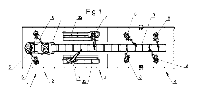
In Figs. 1 and 2, the reference sign 1 altogether denotes an embodiment
variant
of a device according to the invention for carrying out a method for detecting
and
processing by grinding and/or polishing at least one defect 1 with at least
one
grinding or polishing tool 7, 8 in the surface coating of a workpiece 5, which
grinding or polishing tool 7, 8 can be moved automatically and under computer
control over the defect 1 on the basis of a stored program.
As can be seen in Figs. 1 and 2, the device comprises a detection station 2, a
grinding station 3 and a polishing station 4. The individual stations are
interconnected by a rail system 9 on which the workpieces 5 to be processed,
for
example in the form of body parts of a motor vehicle, can be moved from
station
to station and fed to the individual stations in a timed manner.
As shown in Figs. 1,2 and 3, the detection station 2 comprises two robots with
respective robot arms to the end of which an optical scanning device is
attached.
Preferably, the optical sensing device comprises an electromagnetic radiation
source directed towards the workpiece 5 and a detector unit 61 for detecting
and
subsequently evaluating the beams reflected from the workpiece 5.
Date Recue/Date Received 2021-09-16
CA 03133863 2021-09-16
The optical scanning device 6 can optically detect all areas of the surface of
the
workpiece 5 with the help of the movable robot arm.
The robot arm is preferably controlled by a higher-level master computer with
a
database connected to it, in which the relative coordinates of the surface of
the
5 workpiece 5 to be scanned are stored.
Based on the relative coordinates of the surface of the workpiece 5, blocking
areas related to the workpiece 5 are permanently stored or automatically
determined in advance, for example along edges of the workpiece 5, along
grease edges of workpieces 5 designed as body modules, and in tight radii of
the
10 workpiece 5. All necessary parameter variables are stored for the
processing
movement of the robots and are adjusted to the respective defect size. Limit
values are stored for the parameter variables, which can be changed for a
continuous improvement process.
The optical scanning device 6 scans the surface of the workpiece 5, preferably
by
applying a light beam. The reflected radiation is detected by a detector and
any
defects found on the surface of the workpiece 5 are stored digitally in a
second
database.
During storage, the position data and, optionally, a defect weighting are
stored.
Together with the aforementioned database of the master computer, in which the
relative coordinates of the surface of the workpiece 5 are stored, the
detected
defect data are compared with the stored relative coordinates of the workpiece
5
and coordinated with the upcoming further automated processing, i.e. the
grinding treatment and the subsequent polishing treatment.
Depending on the workpiece to be processed, it is also conceivable to provide
only one robot with a defect detection device attached to it in the detection
station 2, or even more than two such robots.
Date Recue/Date Received 2021-09-16
CA 03133863 2021-09-16
11
It is also conceivable, depending on the size of the workpiece or to increase
the
accuracy of the locating process in terms of position data, defect size and
defect
type, to mount the or a further detection unit on the grinding tool itself.
Because the optical scanning device 6 of the detection station 2 can be moved,
it
is also possible to scan workpiece areas that cannot be checked by stationary
locating systems, such as shadow areas or undercuts of the workpiece.
It is also conceivable to detect only the defect position, which eliminates
the
need for extensive and expensive position detection of the carrier vehicle and
the
workpiece.
In this case, the acquisition unit would optically scan the defect area in
advance
and the more accurate data would be used for further processing in step b).
As shown in Figs. 1,2 and 4, two robots are also arranged in the grinding
station
3 adjacent to the detection station 2. In the exemplary embodiment shown here,
the robots are movable along a linear axis 32. It is also conceivable to place
the
robots of the detection station 2 and/or the polishing station 4 on such
linear
axes 32. It is also conceivable to arrange the robots of the grinding station
3 in a
stationary but rotatable manner in the grinding station 3.
Before the grinding tools 7 of the grinding station 3 are controlled by the
master
computer, a simulation of possible movements of the grinding tool 7 for
processing the respective defect is carried out in advance.
If it is determined during such a simulation that automatic processing of the
defect by the grinding tool 7 is not possible, for example due to an
unfavorable
position of the defect for automatic processing, the coordinates of this
defect are
transferred to the master computer and displayed to an employee, preferably
visualized on a screen.
Date Recue/Date Received 2021-09-16
CA 03133863 2021-09-16
12
If the simulation shows that the defect can be processed automatically, the
position data of this defect is forwarded to the master computer for further
processing by grinding. In the process, the grinding tool 7 and the robot arm
to
which the grinding tool 7 is attached are brought into the intended position
in
order to grind the defect.
If, as shown in Figs. 1 and 2, several robots with respective grinding tools 7
are
arranged in the grinding station 3, the workpiece 5 is preferably divided into
several processing areas before the processing data determined for processing
the defect is transferred to the grinding tool 7.
These processing areas are calculated on the basis of the geometry of the
workpiece 5 and the accessibility for a respective grinding tool 7.
Subsequently,
the grinding tool 7 with the lowest time and distance is controlled in such a
way
that the processing of the defect is optimized in terms of time and distance.
When grinding, the preferred method is to grind in concentric grinding paths
around the defect.
In particular, the calculation of the control of the grinding tools 7 and, in
the
subsequent polishing process, also of the polishing tools 8 is carried out
with the
aid of software in such a way that the defective area of the workpiece 5 to be
processed is processed with optimized speed.
When processing the defects, it is also taken into account that, in the case
of
several grinding or polishing tools working simultaneously, the defects can be
processed in parallel without collisions between the grinding or polishing
tools or
between the robots and the robot arms, on each of which such a grinding or
polishing tool is arranged.
Preferably, after the grinding process has been completed, an evaluation is
carried out by the master computer using statistical methods in order to
further
Date Recue/Date Received 2021-09-16
CA 03133863 2021-09-16
13
improve the automation of the processing of the defects, in particular by
reducing the number of processing steps.
The same applies essentially to the polishing of the defects in polishing
station 4,
which is adjacent to grinding station 3.
In the case of workpiece parts that can be moved in their holder by a
predetermined distance, the grinding or polishing tool is aligned accordingly
or it
compensates for slight deviations by gently placing it on the workpiece part
of
the workpiece 5.
Such situations occur, for example, in vehicle bodies with doors, hoods or
flaps
which, after having been previously painted and dried, are not in their closed
position but are only pre-fixed in respective spacers and can be moved into
the
closed position by exerting pressure.
Thus, preferably in the case of opening positions of a section of the
workpiece 5
to be processed of up to 10, such deviations from the stored coordinates are
compensated for by gently placing the processing tools on the section of the
workpiece 5 to be processed in the normal direction.
Alternatively, it is also possible to calculate the opening angle by means of
an
upstream distance sensor before the grinding tool 7, in particular, is set
down
and thus to take it into account during the grinding operation.
As shown in Fig. 4, grinding tools 7 which can work in dry grinding are
preferably
used for the grinding process. For this purpose, the grinding tool 7
preferably
comprises an abrasive belt 71 which, after each grinding operation has been
carried out, is displaced to such an extent that an unused part of the
abrasive
belt is used for the following grinding operation. The abrasive belt 71 is
thereby
preferably held by vacuum on a backing pad of the grinding tool 7.
Date Recue/Date Received 2021-09-16
CA 03133863 2021-09-16
14
This means that intermediate cleaning of the grinding area before polishing is
no
longer necessary, as the area around the defect is completely free of dust and
the abrasive can be changed during breaks, for example.
The micro-grain used here is matched to the polishing paste used. The
preferred
micro-grain size is a micro-grain size outside the FEPA-P range with a maximum
roughness depth of less than 0.5 pm.
In abrasive treatment, the same micro-grain is preferably used for all defect
types or sizes. In the case of larger defects, grinding is carried out several
times,
but always with an unused abrasive, wherein the grinding movement is adapted
to the defect size. By using an unused abrasive, the surface roughness of the
grinding area is within a narrow tolerance range even when processing larger
defects.
As can be seen further in Fig. 5, the polishing tool 8 has a polishing device
attached to a robot arm with a polishing sponge through which the polishing
agent, in particular in the form of a polishing paste, can be supplied. It is
also
conceivable to feed the polishing agent directly onto the grinding point or
into
the polishing sponge itself.
A time-consuming wetting of the polishing sponge surface can be omitted by at
least tripling the polishing paste dosage once after changing the polishing
sponge.
It is also conceivable to reprocess the polishing sponge after use with the
aid of a
pad washer and to continue using it. According to a process variable, the
polishing sponge is then preferably replaced after the third cleaning.
The area of the polishing treatment at the respective defect is preferably
several
times larger than the area of the surface previously processed by grinding.
Especially in the second half of the polishing time, the heat development can
Date Recue/Date Received 2021-09-16
CA 03133863 2021-09-16
thus be minimized by changing the contact pressure and by cooling by means of
compressed air into the polishing sponge.
Furthermore, the polishing tool 8 preferably comprises a wiping device, for
example in the form of a nnicrofiber cloth or a cleaning sponge, in order to
enable
5 automatic wiping of the polishing area. The wiping device is thereby
preferably
attached to a robot arm together with the polishing device 8, wherein the
wiping
device is designed to be pivotable.
Furthermore, the polishing tool 8 preferably comprises a blowing device by
means of which compressed air can be applied to the polishing point for
cooling
10 the latter. In particular for a close cycle, in which the polishing
medium is fed
onto the polishing point into the polishing sponge itself or through the
polishing
sponge to the polishing point, a heat development arising during polishing can
be
minimized in particular by changing the contact pressure of the polishing
sponge
on the point to be polished and by cooling by means of the previously
mentioned
15 compressed air.
It is also conceivable that a detection unit 6 mounted on the polishing tool
optically scans the processed areas and uses this for checking the results.
Date Recue/Date Received 2021-09-16