Note : Les descriptions sont présentées dans la langue officielle dans laquelle elles ont été soumises.
CA 03136107 2021-10-04
WO 2020/206039 PCT/US2020/026267
APPARATUS AND METHODS FOR THE UNDERSTRUCTURE
OF A CHAIR BASE
PRIORITY, CROSS-REFERENCE, AND INCORPORATION
[0001] This application claims priority under 35 U.S.C. 119 to U.S.
Provisional
Patent Application No. 62/829,348 filed April 4, 2019, titled, "APPARATUS AND
METHODS FOR THE UNDERS'TRUCTURE OF A CHAIR BASE". The entire contents of
the above is hereby incorporated into this document by reference and made a
part of this
specification for all purposes, for all that it contains. Moreover, any and
all applications for
which a foreign or domestic priority claim is identified in the Application
Data Sheet of the
present application are hereby incorporated by reference under 37 C.F.R.
1.57.
BACKGROUND
Field
[00021 The disclosure generally relates to features on a chair base.
Related Art
[00031 A chair base can include a structure which supports a chair,
typically an
office chair mounted on wheels, so that the chair can roll around the user's
desk area.
SUMMARY
[0004] For purposes of this summary, certain aspects, advantages, and
novel
features of the embodiments are described herein. It is to be understood that
not necessarily all
such advantages may be achieved in accordance with any particular embodiment
of the
embodiments. Thus, for example, those skilled in the art will recognize that
the embodiments
may be embodied or carried out in a manner that achieves one advantage or
group of
advantages as taught herein without necessarily achieving other advantages as
may be taught
or suggested herein.
100051 In general, vertical forces are compressive in that the weight
of the user
presses down upon the shaft of the chair which is inserted into the central
hub. The rotational
forces are applied about an axis represented by that shaft and occur,
generally, as friction and
other vectors are applied on the arms of the chair base. These experiments
produced a
surprising result in that the concentration of force is focused between the
arms and are not
-1-
CA 03136107 2021-10-04
WO 2020/206039 PCT/US2020/026267
evenly distributed throughout the diameter, nor are they focused predominantly
at the arms
where they connect to the hub.
[00061
Advantageously, the experiments have shown the article of these
embodiments result in outstanding vertical and torsional strength of the arm
to hub relationship
utilizing less material and wall thickness. One of the functional and
structural advantages of
the embodiments is the concentration of strength where the forces exerted on
the chair base
under normal circumstances are concentrated; namely, at the central point on
the outer hub
between the arms, rather than a placement central to the arms where one might
assume. It
should be noted that, throughout this disclosure, "arm" and "leg" may be used
interchangeably
to refer to the appendage on which the roller/casters are mounted on a chair
base of this type.
[0007] This
placement of structural strengthening elements between the arms
yields a surprisingly strong understructure for the chair base. Because of
this advantage and
other related advantages, understructure coring can be increased and wall
thicknesses can be
decreased in certain locations. These ancillary advantages reduce cost by
reducing material
usage, enhance cooling in the injection molding process, and improve tooling
longevity.
[00081 Some
embodiments can include a chair base comprising an understructure
and a top, the chair base further comprising: a central opening configured to
receive a shaft of
a swivel chair; a plurality of arms each configured to accept a caster stem; a
hub surrounding
the central opening and connected to the plurality of arms, the arms generally
extending
radially therefrom in an evenly spaced manner; a
hoop structure encircling the hub and
comprising: a plurality of hoop ribs spaced evenly around the circumference of
the hub and
supporting an outer wall thereof, each hoop rib extending along a radius
aligned with a gap
between two adjacent arms; a hoop wall to which the hoop ribs connect and from
which the
plurality of arms extends; and a plurality of hoop cores comprising voids
surrounded by
adjacent hoop ribs, a portion of the hoop wall, and a portion of an outer wall
of the hub, each
hoop core generally aligned radially with one of the plurality of arms.
100091 In
some embodiments, each arm includes at least one arm rib, wherein the
arm rib is X-shaped.
100101 In
some embodiments, the arm rib is disposed on the understructure of the
chair base and not on the top of the chair base, wherein the top of the chair
base is facing the
swivel chair.
-2-
CA 03136107 2021-10-04
WO 2020/206039 PCT/US2020/026267
[0011] In some embodiments, a portion of the arm rib is tapered via a
variable radii
at an intersection point between the arm rib and the side of the arm.
[0012] In some embodiments, each arm further includes at least one arm
core
comprising a void.
[0013] In some embodiments, the arm core is adjacent to the arm rib and
the hoop
structure.
[0014] In some embodiments, the arm core includes a triangle shape
adjacent to the
arm rib, and an extension shape from the hoop structure.
[0015] In some embodiments, the hoop rib is disposed on the
understructure of the
chair base and not on the top of the chair base.
[0016] In some embodiments, the hoop rib comprises a curved portion
between two
adjacent arms with a radii between 70 to 90 degrees of curvature.
[0017] In some embodiments, the hoop core is disposed on the
understructure of
the chair base and not on the top of the chair base.
[0018] In some embodiments, the hoop core is of generally oval shape.
[0019] In some embodiments, a width of the hoop core is substantially
the same
width of the corresponding arm.
[0020] Some embodiments can include a chair base comprising: a
plurality of arms
each configured to accept a caster stem; a hub surrounding the central opening
and connected
to the plurality of arms, the arms generally extending radially therefrom in
an evenly spaced
manner; a hoop structure encircling the hub and comprising: a plurality of
hoop ribs spaced
evenly around the circumference of the hub and supporting an outer wall
thereof, each hoop
rib extending along a radius aligned with a gap between two adjacent arms; and
a plurality of
hoop cores comprising voids surrounded by adjacent hoop ribs and a portion of
an outer wall
of the hub, each hoop core generally aligned radially with one of the
plurality of arms.
[0021] In some embodiments, each arm includes at least one arm rib,
wherein the
arm rib is X-shaped.
[0022] In some embodiments, a portion of the arm rib is tapered via a
variable radii
at an intersection point between the arm rib and the side of the arm.
[0023] In some embodiments, the hoop rib is disposed on the
understructure of the
chair base and not on the top of the chair base.
-3-
CA 03136107 2021-10-04
WO 2020/206039 PCT/US2020/026267
[0024] In some embodiments, the hoop rib comprises a curved portion
between two
adjacent arms with a radii between 70 to 90 degrees of curvature.
[0025] In some embodiments, the hoop core is disposed on the
understructure of
the chair base and not on the top of the chair base.
[0026] In some embodiments, the hoop core is of generally oval shape.
[0027] In some embodiments, a width of the hoop core is substantially
the same
width of the corresponding arm.
[0028] Some embodiments can include a plastic chair base constructed of
uniform
geometrical modules comprising 3 to 8 arms wherein the outer hub is reinforced
and contains
a single rib between the arms.
[0029] In some embodiments, the under structure is reinforced by a rib
located
between each arm. Said rib is of sufficient thickness to meet specific
vertical and rotational
force requirements.
[0030] In some embodiments, the arm extends from the central hub to the
caster
socket with a rib. Said missing rib creates a void extending to the outer
shell wall thickness.
[0031] In some embodiments, the number of cores immediately adjacent to
the
central hub are in line and the same for each arm.
[0032] In some embodiments, there is a "variable radii" extending from
the bottom
of the arm wall to the inner portion of the outer shell. Such variable radii
improves strength
and minimizes sink/shadowing of the rib understructure on the "A" surface of
the chair base.
[0033] In some embodiments, the first core within the arm creates the
outer ring
wall thickness along with the shell sidewall and top surface. Said core has
generous radii which
prevents notch development.
[0034] In some embodiments, there is no reinforcement rib in line with
the arm at
the center hub.
[0035] In some embodiments, the chair base is produced with between 25
and 35%
GFN 6.
[0036] In some embodiments, the chair based is produced with Post-
industrial
recycled GFN 6.
[0037] In some embodiments, the chair base is produced with Post-
consumer
recycled GFN 6.
-4-
CA 03136107 2021-10-04
WO 2020/206039 PCT/US2020/026267
[0038] In some embodiments, the chair base is produced with between 25
and 35%
GFPP.
[0039] In some embodiments, the mold cavity encapsulates electric
heaters and a
closed loop temperature control system.
[0040] Some embodiments can include an under structure for a chair base
with a
core located outside the central hub in line with each arm. Said core is
molded with high heat
transfer metal.
[0041] In some embodiments, the increased core dimensions provide a
more robust
tool for production.
[0042] In some embodiments, the increased core dimensions provide more
efficient
cooling and increased productivity.
[0043] In some embodiments, the core which molds the central hub is
cooled by
CO2.
[0044] In some embodiments, CO2 is circulated at the base of the high
heat transfer
core resulting in decreased cycle time and high productivity.
[0045] In some embodiments, the arm mold inserts are cooled by CO2.
BRIEF DESCRIPTION OF THE DRAWINGS
[0046] The above-mentioned aspects, as well as other features, aspects,
and
advantages of the present technology will now be described in connection with
various
embodiments, with reference to the accompanying drawings. The illustrated
embodiments,
however, are merely examples and are not intended to be limiting. Like
reference numbers and
designations in the various drawings indicate like elements. Not all of the
elements of the
drawings are in to scale relate to other drawings and the comparative size of
one element
relative to another element in the drawings is not necessarily indicative of
the relative sizes of
the elements in one or more embodiments.
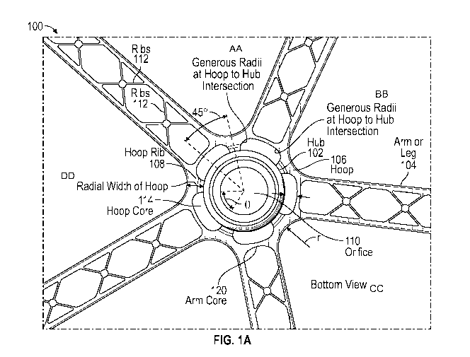
[0047] Figure 1A shows a plan view of the understructure according to
some
embodiments of a chair base described herein. This understructure can be also
referred to as
the "bottom" of the chair base.
[0048] Figure 1B shows a perspective, partially cut-away view of the
central
portion of the chair base of Fig. 1 illustrating the hub, the hoop surrounding
the hub, and the
-5-
CA 03136107 2021-10-04
WO 2020/206039 PCT/US2020/026267
arms/legs extending radially from the hub. This view partially illustrates the
shell of the chair
base which is the upper or "top" portion of the arm structures.
[0049] Figure 2A shows another close up view of the bottom of the chair
base
according to some embodiments.
100501 Figure 2B is a close up perspective view according to some
embodiments.
100511 Figure 3 is another view of the understructure of the chair base
according to
some embodiments.
100521 Figure 4 is a partial cross section of the tapered coring of the
ribs illustrating
an embodiment of the understructure detail incorporation the variable radii at
intersection
points.
[0053] Figure 5 shows a plan view of the cross section of Fig. 5
according to some
embodiments.
[0054] Figure 6 shows another view of the cross section of Fig. 4
according to some
embodiments.
[0055] Figure 7 is a perspective view of the end of an arm showing an
insertion
opening for the shaft of a caster or wheel according to some embodiments.
[0056] Figure 8 is a partial cross section and perspective view of the
chair base hub
and two of the five arms according to some embodiments.
[0057] Figure 9 is a side view of the partial cross section of Fig. 8
according to
some embodiments.
[0058] Figure 10A illustrates a portion of the arm rib that is tapered
via a variable
radii at an intersection point between the arm rib and the side of the arm
according to some
embodiments.
[0059] Figure 10B illustrates tapering of the arm and hoop structure
according to
some embodiments. Figure 10B is an exemplary illustration of the hoop core
that can include
a bottom portion and a top portion according to some embodiments.
100601 Figure 10C illustrates a top view of the chair base according to
some
embodiments.
[00611 Figure 10D illustrates tapering of arm-rib to arm-rib core
according to some
embodiments. Figure 10D further illustrates tapering of arm-rib to side-wall
core according
to some embodiments.
-6-
CA 03136107 2021-10-04
WO 2020/206039 PCT/US2020/026267
[0062] Figure 10E and 1OF illustrates stress distribution of the chair
base according
to some embodiments. Figure 10E illustrates stress distribution of stress
coming from the side
of an arm according to some embodiments. Figure 1OF illustrates stress
distribution of stress
coming from the top of the chair base over an arm, according to some
embodiments.
[0063] Figure 11 is a graph illustrating the results of a strength test
relating to the
current chair base according to some embodiments.
DETAILED DESCRIPTION
100641 In the following detailed description, reference is made to the
accompanying drawings, which form a part of the present disclosure. The
illustrative
embodiments described in the detailed description, drawings, and claims are
not meant to be
limiting. Other embodiments may be utilized, and other changes may be made,
without
departing from the spirit or scope of the subject matter presented here. It
will be readily
understood that the aspects of the present disclosure, as generally described
herein, and
illustrated in the Figures, can be arranged, substituted, combined, and
designed in a wide
variety of different configurations, all of which are explicitly contemplated
and form part of
this disclosure. For example, a system or device may be implemented or a
method may be
practiced using any number of the aspects set forth herein. In addition, such
a system or device
may be implemented or such a method may be practiced using other structure,
functionality,
or structure and functionality in addition to or other than one or more of the
aspects set forth
herein. Elements that are described as "connected," "engaged," "attached," or
similarly
described, shall include being directly and/or indirectly connected, engaged,
attached, etc.
Alterations and further modifications of the inventive features illustrated
herein, and additional
applications of the principles of the inventions as illustrated herein, which
would occur to one
skilled in the art and having possession of this disclosure, are to be
considered within the scope
of the invention.
[0065] Descriptions of unnecessary parts or elements may be omitted for
clarity
and conciseness, and like reference numerals refer to like elements throughout
In the
drawings, the size and thickness of layers and regions may be exaggerated for
clarity and
convenience.
[0066] Features of the present disclosure will become more fully
apparent from the
following description and appended claims, taken in conjunction with the
accompanying
-7-
CA 03136107 2021-10-04
WO 2020/206039 PCT/US2020/026267
drawings. It will be understood these drawings depict only certain embodiments
in accordance
with the disclosure and, therefore, are not to be considered limiting of its
scope; the disclosure
will be described with additional specificity and detail through use of the
accompanying
drawings. An apparatus, system or method according to some of the described
embodiments
can have several aspects, no single one of which necessarily is solely
responsible for the
desirable attributes of the apparatus, system or method. After considering
this discussion, and
particularly after reading the section entitled "Detailed Description" one
will understand how
illustrated features serve to explain certain principles of the present
disclosure.
Example Chair Base
100671 A chair base can include a structure which supports a chair,
typically an
office chair mounted on wheels, so that the chair can roll around the user's
desk area. The
wheels can be mounted on the ends of a plurality of arms which extend out¨in a
spoke-like
manner¨from a central hub of the chair base. A chair base can have a hub and
several arms,
for example.
[0068] Figure 1A illustrates one embodiment of a chair base 100. The
chair base
can include a hub 102 and an arm configuration or structure for the chair base
100. In this
figure, the chair base 100 comprises a hub 102 and a plurality of arms 104.
Portions of the hub
102 may be generally cylindrical or frustoconical shaped. The center of the
hub 102 may
comprise an orifice 110 in order to accept other portions of the chair
assembly; or, the hub 102
may comprise other structures. A plurality of arms 104 may extend from the hub
102. The
arms 104 may extend radially and to some degree in a downward direction. The
outward ends
of the arms 104 may be configured to accept a foot or a caster that will
eventually rest on the
ground once the chair is more fully assembled.
[0069] In some embodiments, the hub 102 may be several inches in
diameter and
several inches in height The hub 102 may include an outside diameter and an
inside
diameter. In some embodiments, the outside diameter of the hub 102 is between
1 and 8
inches; in some embodiments, the outside diameter of the hub 102 is between
approximately
3 and 4 inches. In some embodiments, the height of the hub 102 is between
approximately 2
and 8 inches. The arms 104 may be several inches long and may be long enough
to
adequately support a user once the chair is more fully assembled. The chair
base 100 may be
made from plastic, metal, or other generally durable material. The base 100
may be formed
-8-
CA 03136107 2021-10-04
WO 2020/206039 PCT/US2020/026267
by various manufacturing means, including injection molding, casting,
machining, press-
fitting, etc. The hub 102 and arms 104 may be integrally formed, or may be
made separately
and later assembled.
100701 In Figure 1A, the arms 104 are coupled to the hub 102 by a hoop
(or hoop
structure) 106. The hoop 106 can include a ring-like structure surrounding the
hub. The chair
base 100 can include a plurality of hoop ribs 108. The plurality of hoop ribs
108 can be located
around the circumference of the hub 102. These hoop ribs 108 can tie the arms
104 to the
structure of the central and/or outer hub 102.
[0071] Although the "arms" of the chair base are referred to herein as
arms, it is
understood that they can be referred to as "legs" of the chair base. It is
understood that the
principles and features described herein for the arms could be applied to the
legs or structures
of similar shape and dimension, and vice versa.
[0072] Figure 1A shows a plan view of the understructure of certain
embodiments
of a chair base 100 described herein. This is the understructure because, in
normal use, the
chair base is inverted. Thus, one or more arms of the chair base can comprise
of an upper or
top portion, or shell.
[0073] In some embodiments, one or more arms of the chair base can
comprise arm
ribs 112. The arm ribs 112 can be of an X shape as shown in Figures 1A and 1B.
The arm
ribs 112 can provide strength and/or support.
[0074] The perspective view of Figure 1B illustrates the hub 102, hoop
106, and
extending arms 104 according to some embodiments. The hoop 106 can comprise of
a ring
structure. The hoop 16 can include hoop ribs 108. The hoop ribs 108 can
intersect with the
hub 102 and hoop cores 114 which are formed in molding by the absence of
material and are
interspaced between hoop ribs 108.
[0075] In some embodiments, the shell 116 of each arm 104 can be
generally U-
shaped, as illustrated in Figures 1A, 2B, 8, and 9. Figures 8 and 9 also
illustrate a complete
arm 104 together with an arm end portion having receptacles to receive the
casters for the roller
chair according to some embodiments. Therefore, for purposes of this
description, directional
references such as "above," "upper," "below," or "lower" will refer to the
chair base as shown
oriented in the Figures rather than its orientation in actual use.
-9-
CA 03136107 2021-10-04
WO 2020/206039 PCT/US2020/026267
[0076] Figure 1A illustrates the hub 102 and the five extending arms
104. As noted
above, each arm 104 can comprise an elongate structure comprising a shell 116
and an interior
X-shaped arm rib 112 or truss structure to provide strength and rigidity. The
hub 102 portion
can comprise of two parts, namely, the central or inner portion of the hub 102
and the outer
portion or hoop 106 which is coupled to or integral with the arms 104. The
central hub 102 can
include a cylindrical receptacle for receiving the adjustable air piston which
comprises the
shaft of an office chair or roller chair of the type which is compatible with
the various
embodiments of the present chair base. However, it will be understood that the
features and
principles described herein with respect to the under structure of a chair
base are equally
applicable to other types of chairs and seating apparatus.
[0077] In some embodiments, with respect to the hub 102, the
cylindrical central
hub 102 can extend slightly above the outer hub or hoop as illustrated in
Figure 1B. The central
hub has a small circumferential rim which extends around its upper most region
has shown in
Figure 1B. The outer hoop portion of the hub serves as a connection for the
arms of the chair
base. In this regard, advantageously, the present design and construction of
the chair base
represents an optimal trade-off between strength and material usage. That is,
the present
structure maintains and even improves the strength of the chair base compared
to previous
designs while minimizing the use of material.
[0078] In some embodiments, the chair base is constructed from a
plastic injection
molding process which is relatively well understood by those skilled in the
art. One material
used in the molding process is GFN. However, it will be understood that the
features and
principles described herein apply equally to other types of material or other
modes of
manufacture. The arms are shown integrally molded with the hoop and hub
sections; however,
other forms of attachment are within the scope of the current embodiments.
[0079] In injection molding techniques, where there is an absence of
material due
to the presence of the mold, the hollow space or opening may be referred to as
a "core." Thus,
the coring of the present structure enables the optimal reduction of material
in order to reduce
manufacturing cost, while preserving strength. The coring of the present chair
base is
substantially increased as explained below in more detail. Advantageously, the
coring of the
present embodiments also provides for better cooling of the part during
molding and upon
-10-
CA 03136107 2021-10-04
WO 2020/206039 PCT/US2020/026267
ejection from the injection molding apparatus, as well as less metal fatigue
of the tooling
material.
[0080] An example of a hoop core 114 is shown in Figure 1A adjacent the
hoop
106 and aligned with each arm 104. This example hoop core 114, located
immediately adjacent
the hoop 106, can be referred to as the primary or main hoop core. Five such
cores 106 are
illustrated in Figure 1A located radially and outwardly from the hoop 106.
Each of these hoop
cores 114 can be generally oval shaped, semi-oval shaped, circle shaped, or
other shapes. The
size and placement of these hoop cores 114 represents a significant
improvement over prior
under structures. Each hoop core 114 can be about the same circumferential
length as the width
of an arm at the hoop 106 attachment location.
[0081] In some embodiments, the hoop 106 is attached to the central hub
102
primarily by means of five hoop ribs 108 as shown in Figures 1A and 1B. These
hoop ribs 108
can separate and can be partially formed by adjacent hoop cores 114. Again,
the dimensions
and placement of these hub ribs 118 can substantially improve the strength of
the present chair
base embodiments. These ribs 118 can be formed by radii which simultaneously
provide for
the hoop core dimensions, such as 60, 70, 80, 90, 100, 110, or 120 degrees of
curve.
[0082] In some embodiments, each hoop rib 108 is advantageously placed
between
adjacent arms 104, as shown particularly in Figure 1A. The hoop ribs 108
extend radially away
from the hub 102 to form the hoop 106 or outer ring. The midpoint of each hoop
rib 108 extends
radially between a pair of arms and forms an arm-to-arm connection point,
shown in Figure
IA. This connection point can be about 45 degrees (or 30, 35, 40, 45, 50, 55,
or 60 degrees)
from the midline of the arm.
[0083] In some embodiments, throughout the hub 102/hoop 106 region,
filleted
edges or corners can be provided to relieve stress and preserve strength. This
is particularly
exemplified in the hoop core 114 and midline hoop structure as described above
and illustrated
by Figures 1A and 1B. Extending radially from the hub 102 through the midpoint
of each hoop
core 114 there is shown a portion of the hoop wall 122 which is relatively
thinner.
Advantageously, because of the strength provided by the hoop ribs 108 and
midline arm
connection sections of the hoop 106, the wall 122 thickness of this portion of
the hoop wall
can be reduced in order to decrease material usage.
-11-
CA 03136107 2021-10-04
WO 2020/206039 PCT/US2020/026267
[0084] In some embodiments, with further reference to Figure 1B, the
variable radii
at the X-shaped arm rib 112-to-shell 116 intersections can allow for better
structure structural
strength without visual consequences on the outer surface. It has been
discovered that the
greatest stress is applied near the bottom of the arm 104 and in the hub
102/hoop 106 regions.
Advantageously, the X-shaped arm ribs 112 serve to greatly strengthen the arms
104 while
minimizing material usage. In addition, variable radii at the arm rib 112 to
shell 116
intersection also enhance the strength of the arms 104. These radii increase
as the intersection
is traversed from the upper or top portions of the arm 104 toward the bottom.
Thus, more
material is concentrated near the bottom, as shown by the wider fillet This
effect is also shown
in the cross-section of Figures 8 and 9.
[0085] In some embodiments, all of the hoop cores 114 of the under
structure can
taper slightly in the downward direction; that is, from top to bottom. This
taper increases wall
thickness in the downward direction toward the bottom of the U of the U-shaped
shell. This
taper increases the wall thickness from a thinner wall toward the top of the
under structure to
a thicker wall toward the bottom of the shell 116, as shown and more detail
and Figures 8 and
9. Advantageously, this taper can reduce material usage and provide a draft to
facilitate part
removal from the mold. Similar tapers can be included in all cores of the
illustrated and
described under structure(s) shown in the figures.
[0086] In some embodiments, extending radially outward from the reduced
wall
thickness of the hoop wall is the first arm core 120 of each arm 104, as shown
in Figures lA
and 11. This first arm core 120 exhibits a general house-like shape, shown
particularly well in
the bottom view of Figure 1A, including in cross-section a square with a
triangle extending
radially above it. However, other shapes (e.g., more rounded, rectangular,
shapes with different
number of sides and at different angles) are possible as shown in the
alternate embodiment of
one arm in Figure 1A. Advantageously, it is significant that this first arm
core 120 can have
significantly reduced material usage compared to previous designs. However,
first arm cores
of other dimensions and shapes are within the parameters of the present
disclosure. This first
arm core 120 can be generally large, in order to reduce material usage, and
forms a portion of
the first X-shaped arm rib 112 structure of the arm 104.
Chair Base Features and Advantages
-12-
CA 03136107 2021-10-04
WO 2020/206039 PCT/US2020/026267
[0087] In some embodiments, the described under structures include no
sharp
corners or edges where stress can accumulate and result in points of failure.
Advantageously,
this non-sharp approach reduces material usage while preserving strength.
Figure 2A shows a
GFN plastic base according to some embodiments. In this example, there are no
hoop ribs
central to the arms. The coring is centrally located to each arm and limited
to one per arm.
Figure 2B is an illustration of an example reinforcement rib and variable
radii in the hub
section, according to some embodiments.
[0088] Figure 2A, reference letter A exhibits the larger coring allowed
by
eliminating a central rib aligned with the center axis of an extending arm.
Advantageously, the
larger core can facilitate more uniform wall thickness of the inner and outer
hub, resulting in
better cooling characteristics and lower cycle time. In addition, the mold
that can form this
larger coring can provide a robust metal structure that is more resistant to
cycle metal fatigue.
[0089] In this figure, reference letter B indicates the reduced wall
thickness of the
outer shell aligned with a central elongate axis of an arm. This feature can
have advantages
since the vertical and torsional forces are more concentrated between the
arms, rather than
along the midline of the arms.
[0090] In this figure, reference letter C indicates a grouping or set
of figures
comprising a hub-core-arm module. The figure shows the relationship between
the inner hub,
outer hub or hoop, and arm. In this illustration the base has 5
circumferentially-positioned hub-
core-arm modules. Each arm can be independently connected to the hub in this
manner. In
some embodiments and designs, there are no physical elements shared between
the discreet
arms and hub assembly. However, as shown, the structure can be molded as a
unit such that
the hub-core-arm modules are integrally formed from continuous plastic
material, for example.
[0091] In this figure, reference letter D shows a rib which is
significantly reinforced
between the arm modules where the forces can be focused and strength is
particularly
advantageous.
[0092] In this figure, reference letter E shows a specific location
having
corresponding increased plastic thickness and reinforcement between the arm
modules. This
location can correspond to a zone where two hub-core-arm modules meet,
resulting in
increased plastic thickness. These modules can be formed integrally rather
than independently
or modularly for later assembly.
-13-
CA 03136107 2021-10-04
WO 2020/206039 PCT/US2020/026267
[0093] Figure 2B is a perspective view illustrating an understructure
detail. In
some embodiments, "variable radii" can characterize some or all intersection
points. The radii
can describe contours of a manufacturing mold. For example, if a given
protrusion from a
manufacturing mold forms a right-circular cylinder, the corresponding void (or
core) in the
molded material that it forms will tend to also have a right-circular
cylindrical shape. However,
the right-angle formed by this cylinder will tend to create a sharp corner in
the molded void,
where different walls of plastic join together. Moreover, if adjacent molding
protrusions
(which form adjacent voids) each have vertical parallel wall surfaces, the
resulting wall
between the resulting voids will tend to have a uniform thickness. But uniform
thicknesses rea
often prone to failure (given that stress is typically not uniform) and sharp
corners tend to
concentrate stress. Using mold protrusions with variable radii (and creating
resulting plastic
structures having variable radii) can tend to spread stress and distribute
forces. Similarly,
allowing more material to fill corners where plastic walls meet can reinforce
adjoining walls.
Thus, variable radii approaches can include forming protrusions with rounded
or sloping edges,
and allowing adjacent protrusions to have contoured (rather than straight,
parallel) side walls.
This approach can result in the structures illustrated in Figure 2B, where
voids or cores in the
plastic material have rounded corners. This rounding can also improve the
ability to remove
parts from molds and reduce a failure rate due to mold removal.
[0094] Figure 3 shows a base illustrating features of this disclosure.
Reference
letter A exhibits radii of the coring at the intersection of the middle rib.
The core radii can
span about 120, 130, 140, 150, 160, 170 degrees. Reference letter B exhibits
the first arm core
outside the outer ring of the hub. The core is of substantial size and ties
the arm shell thickness
to the center reinforcement. Reference letter C illustrates the outer ring
around the hoop core.
Reference letter D exhibits the generous and flowing radii of the first arm
core. In this
illustration, the radii refer to the non-uniform (non-circular) shape of the
first arm core side
walls.
[0095] Figure 4 shows a cutaway perspective view of a portion of the
chair base of
Figure 3. This cut-out portion (and those shown in the views of Figures 5 and
6) can comprise
a hub-core-arm module corresponding to label C in Figure 2A, for example.
Reference letters
A and C label remaining portions of adjacent hoop cores. Between these cores
is a radial wall
which ties the hoop ribs between the arms into the central hub/hoop region. In
some
-14-
CA 03136107 2021-10-04
WO 2020/206039 PCT/US2020/026267
embodiments, the radii described herein can be, form or characterize walls
that extend
generally radially from the hub or core. Reference letter B exhibits the wall
thickness of the
central hub, which can be minimized by providing strategic struts of support
at periodic
intervals around its circumference. Reference letter D indicates the first arm
core and radii.
Reference letter E labels a floor (or roof) of the first arm core. Reference
letter F exhibits the
relatively uniform wall thickness of the arm shell.
[0096] Reference letters G and H illustrate taper of the hoop wall. At
the bottom
(G), the hoop wall can be thinner than at the top (H), providing better
strength by distributing
the stress on the bottom to the top while reducing material requirements. This
tapering wall
thickness provides an example of the variable radii approach, which tends to
spread stress and
improve strength and durability. The taper as illustrated here also helps with
the injection
molding manufacturing process, because protrusions of a mold can be tapered
toward their
extremities, reducing the force necessary for disengagement of the molded
material from the
mold tooling itself. Reference letter I illustrates tapering of an
intersection between the hoop
rib and the hub. Reference letter J illustrates tapering of the X-shaped arm
ribs. Tapering
described for one embodiment can be applied to other embodiments, and the
advantages
therein.
Cutout Views of Certain Chair Base Features
[0097] Figure 5 is a top view cutout generally corresponding to the
excerpt shown
in Figures 4 and 6, or a hub-core-arm module (see label B in Figure 2A). This
view helps show
how the structural design elements work together to ultimately result in
optimized physical
properties of the article, the materials, the tooling and numerous other
production benefits.
References A and C label adjacent hoop cores, while reference E labels a
remaining portion of
a first core to X (see Figure 3). Reference D points to a sloping wall for
this core, where one
of the thinner X walls joins with the thicker wall of the radial arm
structure. This sloping wall
can comprise variable radii, either when measured top to bottom and when
measured laterally,
or both.
[0098] Figure 6 is a side view cutout of a hub-core-arm module (see
Figures 4 and
5, and label B in Figure 2A). This is shown from a perspective toward the
central axis of the
chair base.
-15-
CA 03136107 2021-10-04
WO 2020/206039 PCT/US2020/026267
[0099] Figure 7 is a perspective view of a detail of a terminal end of
an arm
corresponding to the insertion opening or caster socket, which receives the
shaft of a caster or
wheel. This design feature improves both vertical and rotational strength.
This view also
illustrates the last core at the end of the arm or leg showing a full rounded
filleted core with
enhanced strength and reduced material usage.
[0100] The cross-sectional views of Figures 8 and 9 illustrate the
variable radii
features of the X-shaped ribs and shell of the arms. In many cases the wall
thickness are
uniform. In other locations, where forces are concentrated, the walls are
tapered to strategically
distribute material in those regions. The cutaway view of Figure 9 shows how
the bottom of
the hoop cores (their roofs when the chair base is in use) can be rounded,
which provies
strength, weight and stress distribution, and mold-removal benefits.
Advantages of Thinner. More Uniform Wall Thicknesses
[0101] In some embodiments, the present embodiments allow the chair
base to
exhibit thinner wall thickness in many key areas of the design. This is an
important and
surprising advantage when one considers the significant forces which are
exerted on a chair
base of the type described. Reduced wall thicknesses bring about many
advantages in the
injection molding process. Prior to ejection from the mold, injection molded
parts are cooled
down from manufacturing temperatures so that they hold their shape when
ejected. During the
part cooling step of the molding process, changes in pressure, velocity and
plastic viscosity
should be minimized to avoid defects. One of the important aspects of the
present chair base
embodiment is wall thickness. This feature can have major effects on the cost,
production
speed and quality of the final parts.
[0102] Designing the proper chair base wall thickness can have
significant effects
on the cost and production speed of manufacturing. While preserving the trade
off with
strength, the goal is to choose the thinnest wall possible. Advantageously,
thinner walls use
less material which reduces cost and take less time to cool, reducing cycle
time. The minimum
wall thickness that can be used depends on the size and geometry of the part,
structural
requirements, and flow behavior of the resin. The wall thicknesses of an
injection molded part
generally range from 2mm - 4mm (0.080" - 0.160").
[0103] Thick sections take longer to cool than thin ones. During the
cooling
process, if walls are an inconsistent thickness, the thinner walls will cool
first while the thick
-16-
CA 03136107 2021-10-04
WO 2020/206039 PCT/US2020/026267
walls are still solidifying. As the thick section cools, it shrinks around the
already solid thinner
section. This causes warping, twisting or cracking to occur where the two
sections meet. To
avoid this problem, the present chair base embodiments have virtually
completely uniform
walls throughout the part. Where the walls are not of uniform thickness, the
change in thickness
is gradual. Advantageously, the wall thickness tapers described above not only
reduce material
usage, but also avoid defects during cooling. In the current designs, wall
thickness variations
do not exceed 10% in high mold shrinkage plastics. Thickness transitions are
gradual; on the
order of 3 to 1. This gradual transition avoids stress concentrations and
abrupt cooling
differences. Also, the fillets and chamfered comers described above minimize
the dramatic
change in pressures inside the mold.
[0104] In some embodiments, the present under structure provides less
stress points
and reduced material. Figure 10A is an exemplary illustration of a portion of
the arm rib that
is tapered via a variable radii at an intersection zone 1002 between the arm
rib and the side of
the arm according to some embodiments. The taper can be wider (or a larger
radius) at the
bottom than that of the top.
[0105] Figure 10B illustrates tapering of the arm and hoop structure
according to
some embodiments. The arm core 120 can include a bottom portion 1004 and a top
portion
1006. As can be seen, the bottom portion 1004 of the arm core 120 is larger
than the top
portion 1006 of the arm core 120. This is due to the variable radii 1008 of
the taper from the
top portion 1006 to the bottom portion 1004.
[0106] Figure 10B is an exemplary illustration of the hoop core 114
that can include
a bottom portion 1010 and a top portion 1012 according to some embodiments. As
can be
seen, the bottom portion 1010 of the hoop core 114 is larger than the top
portion 1012 of the
hoop core 114. This is due to the variable radii 1014 of the taper from the
top portion 1012 to
the bottom portion 1010.
[0107] Figure 10C illustrates a top view of the chair base according to
some
embodiments. As shown, the cores of the chair base, such as the arm core and
hoop core, are
located on the understructure of the chair base and not on the top of the
chair base.
[0108] Figure 10D illustrates tapering of arm-rib to arm-rib core
according to some
embodiments. The arm-rib to arm-rib core 1022 is between arm rib 1024 and arm
rib 1026.
The arm-rib to arm-rib core 1022 can include a bottom portion 1028 and a top
portion 1030.
-17-
CA 03136107 2021-10-04
WO 2020/206039 PCT/US2020/026267
As can be seen, the bottom portion 1028 of the arm-rib to arm-rib core 1022 is
larger than the
top portion 1030 of the arm-rib to arm-rib core 1022. This is due to the
variable radii 1032,
1034 of the taper from the top portion 1030 to the bottom portion 1028.
[0109] Figure 10D further illustrates tapering of arm-rib to side-wall
core 1036
according to some embodiments. The arm-rib to side-wall core 1036 is between
arm rib 1024
and a side wall 1038 of the arm. The arm-rib to side-wall core 1036 can
include a bottom
portion 1042 and a top portion 1040. As can be seen, the bottom portion 1042
of the arm-rib
to side-wall core 1036 is larger than the top portion 1040 of the arm-rib to
side-wall core 1036.
This is due to the variable radii of the taper 1044 from the bottom portion
1042 and a top
portion 1040.
[0110] Figure 10E and 1OF illustrates stress distribution of the chair
base according
to some embodiments. Figure 10E illustrates stress distribution of stress
coming from the side
of an arm according to some embodiments. The stress can be distributed through
the side-
walls of the arm and throughout the ribs. Figure 1OF illustrates stress
distribution of stress
coming from the top of the chair base over an arm, according to some
embodiments. The stress
can be distributed throughout the side-walls of the arm and through the ribs,
through the hoop
structure including the hoop wall and hoop ribs, to the hub, and to the other
arms. The features
of the chair base can distribute stress in an effective manner while reducing
material
requirements.
[0111] Advantageously to some embodiments herein, there is less need
for material
while providing strengthening for weight at the bottom. The reduction of
material allows for
faster cooling, as the design allows for thinner walls. Moreover, the taper
allows for ease of
removal from the mold injection machine.
Test Results
[0112] Two types of testing have confirmed the advantages of the
current chair
base embodiments. Such tests are standard in the chair base industry for
minimum safety and
strength. In both cases, the chair base of the current embodiments exceed
these minimum
standards by a wide margin.
[0113] In a first test, known as the static load test or BIFMA test, a
chair base to be
tested is supported at the end of each arm (without casters) and a vertical
load is applied at the
-18-
CA 03136107 2021-10-04
WO 2020/206039 PCT/US2020/026267
hub. The minimum standard for this test is 2500 psi, applied twice for a
specified period of
time. Failure should not occur. In one test, as shown in Figure 11, one chair
base of the current
embodiments did not fail until 3995 psi was applied. In another test (not
shown), failure did
not occur until 4760 psi was reached.
[0114] Another test is known as the drop test. A chair base, with
casters, is placed
on a solid surface and a 300 lbs load is dropped from 6 inches on the hub.
Failure should not
occur. Because of the presence of casters, this test helps determine whether
the chair base can
withstand not only the vertical load but also the torsional forces applied to
the arms.
[0115] Embodiments of the present disclosure have been tested and shown
to not
fail until the load was dropped from 12 inches.
Other Embodiments
[0116] Many variations and modifications may be made to the above-
described
embodiments, the elements of which are to be understood as being among other
acceptable
examples. All such modifications and variations are intended to be included
herein within the
scope of this disclosure. The foregoing description details certain
embodiments. It will be
appreciated, however, that no matter how detailed the foregoing appears in
text, the systems
and methods can be practiced in many ways. As is also stated above, it should
be noted that
the use of particular terminology when describing certain features or aspects
of the systems
and methods should not be taken to imply that the terminology is being re-
defined herein to be
restricted to including any specific characteristics of the features or
aspects of the systems and
methods with which that terminology is associated.
[0117] Various modifications to the implementations described in this
disclosure
may be readily apparent to those skilled in the art, and the generic
principles defined herein
may be applied to other implementations without departing from the spirit or
scope of this
disclosure. Thus, the claims are not intended to be limited to the
implementations shown
herein, but are to be accorded the widest scope consistent with this
disclosure, the principles
and the novel features disclosed herein. Additionally, a person having
ordinary skill in the art
will readily appreciate, the terms "upper" and "lower" are sometimes used for
ease of
describing the figures, and indicate relative positions corresponding to the
orientation of the
figure on a properly oriented page, and may not reflect the proper orientation
of the device as
implemented.
-19-
CA 03136107 2021-10-04
WO 2020/206039 PCT/US2020/026267
[0118] Certain features that are described in this specification in the
context of
separate implementations also can be implemented in combination in a single
implementation.
Conversely, various features that are described in the context of a single
implementation also
can be implemented in multiple implementations separately or in any suitable
sub combination.
Moreover, although features may be described above as acting in certain
combinations and
even initially claimed as such, one or more features from a claimed
combination can in some
cases be excised from the combination, and the claimed combination may be
directed to a sub
combination or variation of a sub combination.
[0119] Similarly, while operations are depicted in the drawings in a
particular
order, this should not be understood as requiring that such operations be
performed in the
particular order shown or in sequential order, or that all illustrated
operations be performed, to
achieve desirable results. Further, the drawings may schematically depict one
more example
processes in the form of a flow diagram. However, other operations that are
not depicted can
be incorporated in the example processes that are schematically illustrated.
Additionally, other
implementations are within the scope of the following claims. In some cases,
the actions
recited in the claims can be performed in a different order and still achieve
desirable results.
[0120] Conditional language, such as, among others, "can," "could,"
"might," or
"may," unless specifically stated otherwise, or otherwise understood within
the context as used,
is generally intended to convey that certain embodiments include, while other
embodiments
do not include, certain features, elements, and/or steps. Thus, such
conditional language is not
generally intended to imply that features, elements and/or steps are in any
way required for
one or more embodiments or that one or more embodiments necessarily include
logic for
deciding, with or without user input or prompting, whether these features,
elements and/or
steps are included or are to be performed in any particular embodiment.
[0121] The term "substantially" can mean that the recited
characteristic, parameter,
or value need not be achieved exactly, but that deviations or variations,
including for example,
tolerances, measurement error, measurement accuracy limitations and other
factors known to
those of skill in the art, may occur in amounts that do not preclude the
effect the characteristic
was intended to provide. The term "substantially" can mean a 0.01%, 0.1%, 1%,
5%, or 10%
difference.
-20-
CA 03136107 2021-10-04
WO 2020/206039 PCT/US2020/026267
[0122] The term "substantially" when used in conjunction with the term
"real-time"
forms a phrase that will be readily understood by a person of ordinary skill
in the art. For
example, it is readily understood that such language will include speeds in
which no or little
delay or waiting is discernible, or where such delay is sufficiently short so
as not to be
disruptive, irritating, or otherwise vexing to a user.
10123] Conjunctive language such as the phrase "at least one of X, Y,
and Z," or
"at least one of X, Y, or Z," unless specifically stated otherwise, is to be
understood with the
context as used in general to convey that an item, term, etc. may be either X,
Y, or Z, or a
combination thereof. For example, the term "o r" is used in its inclusive
sense (and not in its
exclusive sense) so that when used, for example, to connect a list of
elements, the term "or"
means one, some, or all of the elements in the list Thus, such conjunctive
language is not
generally intended to imply that certain embodiments require at least one of
X, at least one of
Y, and at least one of Z to each be present.
[0124] The term "a" as used herein should be given an inclusive rather
than
exclusive interpretation. For example, unless specifically noted, the term "a"
should not be
understood to mean "exactly one" or "one and only one"; instead, the term "a"
means" one or
more" or "at least one," whether used in the claims or elsewhere in the
specification and
regardless of uses of quantifiers such as "at least one," "one or more," or "a
plurality" elsewhere
in the claims or specification.
[0125] The term "plurality" refers to two or more of an item. The term
"about"
means quantities, dimensions, sizes, formulations, parameters, shapes and
other characteristics
need not be exact, but may be approximated and/or larger or smaller, as
desired, reflecting
acceptable tolerances, conversion factors, rounding off, measurement error and
the like and
other factors known to those of skill in the art.
[0126] The term "comprising" as used herein should be given an
inclusive rather
than exclusive interpretation. For example, a general purpose computer
comprising one or
more processors should not be interpreted as excluding other computer
components, and may
possibly include such components as memory, input/output devices, and/or
network interfaces,
among others.
[0127] While the above detailed description has shown, described, and
pointed out
novel features as applied to various embodiments, it may be understood that
various omissions,
-21-
CA 03136107 2021-10-04
WO 2020/206039 PCT/US2020/026267
substitutions, and changes in the form and details of the devices or processes
illustrated may
be made without departing from the spirit of the disclosure. As may be
recognized, certain
embodiments of the embodiments described herein may be embodied within a form
that does
not provide all of the features and benefits set forth herein, as some
features may be used or
practiced separately from others. The scope of certain embodiments disclosed
herein is
indicated by the appended claims rather than by the foregoing description. All
changes which
come within the meaning and range of equivalency of the claims are to be
embraced within
their scope.
[01281 It should be noted that various changes and modifications to the
presently
preferred embodiments described herein will be apparent to those skilled in
the art. Such
changes and modifications may be made without departing from the spirit and
scope of the
invention and without diminishing its attendant advantages. For instance,
various components
may be repositioned as desired. It is therefore intended that such changes and
modifications
be included within the scope of the invention. Moreover, not all of the
features, aspects and
advantages are necessarily required to practice the present invention.
Accordingly, the scope
of the present invention is intended to be defined only by the claims that
follow.
[0129] Numerical data may be expressed or presented herein in a range
format. It
is to be understood that such a range format is used merely for convenience
and brevity and
thus should be interpreted flexibly to include not only the numerical values
explicitly recited
as the limits of the range, but also interpreted to include all of the
individual numerical values
or sub-ranges encompassed within that range as if each numerical value and sub-
range is
explicitly recited. As an illustration, a numerical range of "about 1 to 5"
should be interpreted
to include not only the explicitly recited values of about 1 to about 5, but
also include individual
values and sub-ranges within the indicated range. Thus, included in this
numerical range are
individual values such as 2, 3 and 4 and sub-ranges such as 1-3, 2-4 and 3-5,
etc. This same
principle applies to ranges reciting only one numerical value (e.g., "greater
than about 1") and
should apply regardless of the breadth of the range or the characteristics
being described. A
plurality of items may be presented in a common list for convenience. However,
these lists
should be construed as though each member of the list is individually
identified as a separate
and unique member. Thus, no individual member of such list should be construed
as a de facto
-22-
CA 03136107 2021-10-04
WO 2020/206039 PCT/US2020/026267
equivalent of any other member of the same list solely based on their
presentation in a common
group without indications to the contrary.
[0130] Furthermore, where the terms "and" and "or" are used in
conjunction with
a list of items, they are to be interpreted broadly, in that any one or more
of the listed items
may be used alone or in combination with other listed items. The term
"alternatively" refers to
selection of one of two or more alternatives, and is not intended to limit the
selection to only
those listed alternatives or to only one of the listed alternatives at a time,
unless the context
clearly indicates otherwise.
-23-