Note : Les descriptions sont présentées dans la langue officielle dans laquelle elles ont été soumises.
Hygienic Conveyor Roller
Field of the Invention
The present application relates to power-driven conveyors. More particular,
the
present invention relates to rollers used to support a conveyor belt in a
returnway, infeed or
.. another location where a conveyor belt requires support.
Background of the Invention
Conveyor belts are used in many industries to convey products from first
location to
a second location. Conveyor belts generally form an endless belt loop that is
trained around
drive and idler sprockets or rollers at each end of a conveying path. Articles
are conveyed
atop the conveyor belt are supported along an upper carryway. The conveyor
belt returns
along a lower returnway. To minimize the maximum sag of the conveyor belt in
the
returnway, return shoes or rollers are often used. Return rollers typically
extend across the
width of the conveyor belt at selected positions along the returnway. Rollers
may also be
used to support a conveyor belt at the infeed end of the endless conveyor belt
circuit and ¨
or another location. Traditionally, many applications use full width rollers
that extend along
the width of the conveyor belt. However, in food-related applications, the
full width roller
contacts the entire surface of the conveyor belt and can smear and co-mingle
remaining food
product on the surface of the belt, compromising food safety.
One option in use is a stationary stainless-steel mounting shaft with multiple
reduced diameter journals. Plastic disks with bores of a similar diameter to
the shaft can be
slid over the shaft and positioned into the journals. An advantage of this
solution is that the
conveyor belt is supported but has limited contact between the roller and the
belt surface,
improving food safety.
A drawback to the roller disks is that they create potential sandwiches
between the
inner diameter of the roller and the outer diameter of the shaft journal.
These sandwiches
cannot be cleaned in place while the belt is running and must be manually
lifted and
removed to clean both the shaft the and entire surface of the roller disk.
To simplify the cleaning of these rollers in place, clearance is added either
to the bore
of the roller or the length of the shaft journal. While this does not enable a
complete clean in
place solution, it does enable some cleaning of the roller while still
situated on the shaft.
1
Date recue/date received 2021-10-28
However, the additional clearances also enable the roller to move axially and
to also tip
when exposed to lateral forces, creating instability.
Summary of the Invention
A hygienic, cleanable conveyor roller for use in a conveyor includes a
segmented
hub, a plurality of spokes and a rim for contacting a conveyor belt. The
segmented hub
comprises a plurality of arcuate segments in different axial planes connected
to each other to
form a hub with an axial bore for receiving a mounting shaft. The conveyor
roller is
mounted upon and rotatable about a mounting shaft that may axially constrain
the roller.
During a single revolution of the conveyor roller about the mounting shaft,
all surfaces of
both the conveyor roller and the mounting shaft are fully exposed, allowing
the surfaces to
be cleaned in place, without requiring removal of the conveyor roller from the
mounting
shaft.
According to one aspect, a roller for a conveyor comprises a segmented hub
formed of a plurality of overlapping and connected segments to form an opening
for
receiving a shaft about which the conveyor roller is mounted, at least one
spoke extending
radially from the segmented hub and a rim connected to the segmented hub via
the at least
one spoke.
According to another aspect, a roller assembly for a conveyor comprises a
mounting shaft including a cylindrical body extending along an axis and a
mounting region
formed in the body and a conveyor roller rotatably mounted in the mounting
region. The
conveyor roller comprises a segmented hub formed of a plurality of overlapping
and
connected segments to form an opening for receiving the mounting shaft, at
least one spoke
extending radially from the segmented hub and a rim connected to the segmented
hub via
the at least one spoke.
Brief Description of the Drawings
FIG. 1 is an isometric view of a conveyor roller including a segmented hub
mounted
on a mounting shaft according to an embodiment;
FIG. 2 is an isometric view of the conveyor roller of FIG. 1;
2
Date recue/date received 2021-10-28
FIG. 3 is an isometric view of an isolated arcuate segment of the segmented
hub of
the conveyor roller of FIG. 1;
FIG. 4 is an isometric view of a mounting shaft with a mounting region
suitable for
mounting the conveyor roller of FIG. 2;
FIG. 5 is a front view of the conveyor roller and mounting shaft of FIG. 1;
FIG. 6 is a cross-sectional front view of FIG. 5;
FIG. 7 is a cross-sectional view of the conveyor roller and mounting shaft of
FIG. 1
through an axial plane that bisects the conveyor roller;
FIG. 8 is a side view of the conveyor roller and mounting shaft of FIG. 1;
FIG. 9 is an isometric view of the conveyor roller and mounting shaft of FIG.
1 prior
to mounting the conveyor roller on the mounting shaft;
FIG. 10 is an isometric view of the conveyor roller and mounting shaft of FIG.
1
during mounting of the conveyor roller on the mounting shaft;
FIG. 11 is an isometric view of the conveyor roller and mounting shaft of FIG.
1 in a
first position;
FIG. 12 is an isometric view of the conveyor roller and mounting shaft of FIG.
11
after a quarter-revolution of the conveyor roller about the mounting shaft;
FIG. 13 is an isometric view of the conveyor roller and mounting shaft of FIG.
11
after a half-revolution of the conveyor roller about the mounting shaft;
FIG. 14 is an isometric view of the conveyor roller of FIG. 2 during mounting
of the
conveyor roller on a mounting shaft according to another embodiment;
FIG. 15 is an isometric view of the conveyor roller of FIG. 14 in a first
mounted
position on the mounting shaft;
FIG. 16 is a front view of the conveyor roller and mounting shaft of FIG. 15;
FIG. 17 is a cross-sectional view of the conveyor roller and mounting shaft of
FIG. 16.
Detailed Description
A hygienic conveyor roller includes a segmented hub connected to a rim with
spokes. The invention will be described below relative to certain illustrative
embodiments,
though those skilled in the art will recognize that the invention is not
limited to the
described embodiments.
3
Date recue/date received 2021-10-28
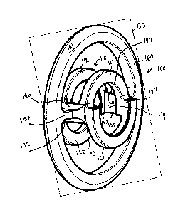
Referring to FIGS. 1-8, a conveyor roller 100 is mounted on and rotatable
about a
mounting shaft 10 in a conveyor. In one embodiment, the conveyor roller is a
returnway
roller, mounted in the returnway of a conveyor for guiding and ¨or supporting
the
conveyor belt as it travels from the outfeed, discharge end, back to the
infeed of the
conveyor. As the conveyor belt moves over the outer rim 160 of the conveyor
roller 100, it
may spin the conveyor roller 100 about the shaft 10. One skilled in the art
will recognize that
the illustrative conveyor roller 100 may be implemented in any suitable
location in a
conveyor, such as the infeed or other suitable location where support of a
conveyor belt is
useful.
The conveyor roller 100 comprises a segmented hub 110 that is mounted on and
rotatable about the shaft 10 in a dedicated mounting region 20. The segmented
hub 110
comprises a plurality segments in different axial planes that connect to and
overlap each
other to form a complete, unitary hub that can encircle a mounting shaft 10
and allow
rotation of the conveyor roller 100 about the mounting shaft 10.
Spokes 150 extend radially from the segmented hub 110 and connect the
segmented
hub 110 to the outer rim 160, the outer surface 161 of which contacts and
supports a
conveyor belt. The illustrative conveyor roller 100 includes two spokes 150 in
line with and
parallel to each other and radially offset from each other by 180 , but the
invention is not so
limited. For example, more spokes may be used to connect the segmented hub 110
to the rim
160. Alternatively, webbing or another suitable connector may connect the
segmented hub
110 to the rim 160.
The illustrative segmented hub 110 comprises a first arcuate segment 111 and a
second arcuate 112 segment parallel to and spaced from the first arcuate
segment 111. The
first and second arcuate sections are equally spaced from a central vertical
plane 50 that
bisects the roller 100, and mirror each other across the central vertical
plane 50. A third
arcuate segment 121 is radially and axially offset from the first arcuate
segment 111, such
that the ends of the first arcuate segment 111 overlap and connect with the
ends of the third
arcuate section to form first and second overlapping portions 140, 141. A
fourth arcuate
segment 122 is radially and axially offset from the second arcuate segment
112, such that the
ends of the second arcuate segment 112 overlap and connect with the ends
fourth arcuate
segment 122 to form third and fourth overlapping portions 142, 143.
4
Date recue/date received 2021-10-28
In the illustrative embodiment, the shape and size of the arcuate segments are
substantially identical, with each segment spanning greater than 1800, so that
the
overlapping and offset segments 111, 112, 121, 122 form a complete
circumference having an
axial bore with a substantially circular cross-section that is slightly bigger
than the outer
diameter of the shaft 10 to allow the segmented hub 110 to slide over the main
body of the
mounting shaft 10.
Alternatively, three, four or more offset, overlapping and connected segments
may
form a complete circumference forming an axial bore for receiving the mounting
shaft 10.
A first bridging segment 146 extends between the first arcuate segment 111 and
the
second arcuate segment 112. The illustrative first bridging segment 146
extends between the
first overlapping portion 140 and the third overlapping portions 142 to
connect the first and
second arcuate sections 111, 112 to the third and fourth arcuate sections 121,
122. However,
the first bridging segment 146 may be radially offset from the overlapping
portions 140, 142,
and¨or extend between any suitable locations of the arcuate segments 111, 112,
121, 122.
A second bridging segment 147 extends the first arcuate segment 111 and the
second
arcuate segment 112 at a second location. The illustrative second bridging
segment 147
extends between the second overlapping portion 141 and the fourth overlapping
portion 143
to further connect the connect the first and second arcuate sections 111, 112
to the third and
fourth arcuate sections 121, 122 at the opposite end. The second bridging
segment 147 can be
radially offset from the overlapping portions 142, 143 and¨or extend between
any suitable
locations to connect the arcuate segments 111, 112, 121, 122 together.
Each illustrative spoke 150 extends from the radially outer side of the
associated
bridging segment 146, 147. Alternatively, the spokes 150 or other suitable
segmented hub-to-
rim connector may be located in a different location or various locations, and
the invention
is not limited to spokes extending from bridging segments on the segmented hub
110.
As shown in FIG. 2, the radially inner surface 145 of each of the bridging
segments
146, 147 is radially offset outwards from the radially inner surfaces of the
arcuate segments
to provide clearance.
The illustrative conveyor roller 100 has mirror image symmetry across the
plane 50,
which bisects the rim 160.
5
Date recue/date received 2021-10-28
FIG. 3 shows an isolated arcuate segment 170 representing each arcuate segment
111,
112, 121 and¨or 122 according to an embodiment. The illustrative arcuate
segment 170
includes a radially outer surface 171, a radially inner surface 172, an
axially outer surface
173, an axially inner surface 174 and end surfaces 175, 176. The illustrative
arcuate segment
spans more than 1800, so that the ends 175, 176 are separated by less than 180
, but the
invention is not so limited. The illustrative arcuate segment has a
rectangular or square
cross-section, with flat axially inner and outer surfaces 173, 174. Shaped
connecting surfaces
may connect the arcuate segment to an adjacent arcuate segment to prevent
crevices and
smooth the interface between the segments. The illustrative end surfaces 175,
176 extend
parallel to a line 178 extending tangent the apex 179 of the arcuate segment.
In this manner,
when the apex 179 is at its topmost point, the end surfaces 175, 176 are
horizontal, as shown
in FIGS. 7 and 8. The ends 175, 176 of one or more of the arcuate segment may
be
chamfered.
While FIG. 3 shows an arcuate segment 170 in isolation, the illustrative
conveyor
roller 100 comprises a segmented hub 110 in which the segments 111, 112, 121,
122 are
integrally formed through injection molding, compression molding or another
suitable
process. The entire conveyor roller 100 may be integrally formed through
injection molding,
compression molding or another suitable process. Alternatively, one or more
portions or
segments of the conveyor roller 100 may be separately formed and then
connected together.
The conveyor roller 100 is configured to receive a mounting shaft 10 that
axially and
radially constrains the movement of the conveyor roller 100, while allowing
rotation of the
conveyor roller 100 about the mounting shaft 10. In one embodiment, shown in
FIG. 4, the
shaft 10 comprises a cylindrical body 11 with an outer surface 12 and
extending along an
axis 16. The mounting shaft 10 includes one or more mounting regions 20, each
capable of
mounting a conveyor roller 100. The illustrative mounting region 20 comprises
a first
eccentric radial groove 30 and a second eccentric radial groove 40 parallel to
and separated
from the first eccentric radial groove 30 by a ridge 60. The illustrative
outer surface of the
ridge 60 matches the outer surface 12 of the cylindrical body 11, but could
alternatively be
inset or offset from the outer surface 12.
The illustrative eccentric radial grooves 30, 40 form a plurality of crescent-
shaped flat
side surfaces 31, 32, 41, 42 extending perpendicular to the axis 16 of the
mounting shaft 10.
6
Date recue/date received 2021-10-28
The radial outer surfaces 35, 45 of the grooves 30, 40 are inset from the
outer surface 12 of
the main body of the mounting shaft 10. The grooves 30, 40 each have an axial
width Wg that
is slightly larger than the combined width Ws of each of the paired segments
111, 121 and
112, 122, as shown in FIG. 5.
FIGS. 5-8 show the conveyor roller 100 is mounted on the mounting shaft 10 in
the
mounting region 20 in a first position, with the first and second arcuate
segments 111, 112
circumscribing the top of the mounting shaft 10, such that the apexes 179 of
the first and
second arcuate segments are at a topmost point. In this first position, the
third and fourth
arcuate segments 121, 122 circumscribe the bottom of the mounting shaft 10.
The axially
inner surfaces 174 of the first and second arcuate segments are constrained by
the inner side
surfaces 32, 41 on the ridge 60. The inner radial surfaces 172 of the first
and second arcuate
segments 111, 112 ride over the radial outer surfaces 35, 45 of the grooves
30, 40. Outer axial
surfaces of third and fourth segments 173 reach to the outer side surfaces 31,
42 of the
grooves. The segmented hub 110 provides a clearance space 180 between the
third and
fourth arcuate segments 121, 122 and the bottom of the mounting shaft 10.
Referring to FIGS. 9-13, the conveyor roller 100 can be easily mounted on the
mounting shaft 10 without tools and rotate about the mounting shaft during
operation.
During each revolution of the conveyor roller 100 about the mounting shaft 10,
all surfaces
of the segmented hub 110 and mounting region 20 of the mounting shaft 10 are
exposed to
enable cleaning, without requiring the conveyor roller 100 to be dismounted
from the
mounting shaft 10.
In a first step, shown in FIG. 9, the axial bore of the segmented hub 110 is
aligned
with the mounting shaft 10 axial axis 16, then slid over the outer periphery
12 of the
mounting shaft 10 until it reaches the mounting region 20, as shown in FIG.
10. In the
illustrative embodiment, the conveyor roller 100 is mounted with the apexes
179 of the first
and second arcuate segments 111, 112 in the topmost position. When centered
over the
mounting region 20 in such a position, the radially inner surfaces 172 of the
arcuate
segments 111, 112, 121, 122 are centered about the axis 16 of the mounting
shaft, providing
clearance 181 between the radially outer surfaces 35, 45 of the grooves 30, 40
and the radially
inner surfaces 172 of the first and second arcuate segments 111, 112. When a
user releases
the conveyor roller 100, the conveyor roller 100 drops into place, such that
the axially inner
7
Date recue/date received 2021-10-28
surfaces 174 of the first and second arcuate segments abut the inner side
surfaces 32, 41 on
the ridge 60, the inner radial surfaces 172 of the first and second arcuate
segments 111, 112
sit on the radial outer surfaces 35, 45 of the grooves 30, 40 and the outer
axial surfaces of
third and fourth segments 173, which circumscribe the bottom of the shaft and
are spaced
from the bottom of the shaft, reach to the outer side surfaces 41, 42 of the
grooves, as shown
in FIG. 11. The conveyor roller can alternatively mount in a different
position.
FIGS 11-13 show the conveyor roller 100 as it rotates through one-half a
revolution in
the direction of the arrow 19. After rotation through 900, as shown in FIG.
12, the segmented
hub 110 is oriented with the first and second arcuate sections 111, 112
spanning a side of the
mounting shaft, from a top to an opposite bottom, exposing certain surfaces
for cleaning.
FIG. 13 shows the conveyor roller 100 after it has rotated through an
additional 90 , so that
the third and fourth arcuate sections 121, 122 are seated in the grooves 30,
40 and
circumscribe the top of the mounting shaft 10. In this position, the axially
outer surfaces 173
of the third and fourth arcuate sections abut and are constrained by the outer
side surfaces
31, 42 of the grooves 30, 40, and additional surface area is exposed for
cleaning. The radially
inner surfaces 172 of the third and fourth arcuate sections 121, 122 contact
and ride over the
radially outer surfaces 35, 45 of the grooves. The first and second arcuate
sections 111, 112,
now circumscribing the bottom of the mounting shaft 10, are spaced from the
bottom of the
shaft 10 to provide clearance 182 between the radially inner surfaces 172 of
the first and
second arcuate sections 111, 112 and the mounting shaft 10. As the conveyor
roller 100
returns to the first position of FIG. 11, additional surfaces are exposed for
cleaning without
removing the conveyor roller 100 from the mounting shaft 10.
In any radial position on the mounting shaft 10, the conveyor roller 100 has
at least
two radially inner surfaces 172 of the arcuate sections 111, 112, 121 and-or
122 in contact
with the radially outer surface of the mounting shaft. In addition, in any
radial position, the
conveyor roller has at least two axial surfaces 173 or 174 of the arcuate
sections 111, 112, 121
and-or 122 in contact with or abutting side surfaces 31, 32, 41 and-or 42 of
the shaft
grooves 30, 40 to constrain the conveyor roller 100 to the mounting region 20
of the shaft.
The conveyor roller 100 can be used with any suitable mounting shaft. lil
another
embodiment, shown in FIGS. 14-17, a mounting shaft 210 can comprise
circumferential
grooves 230, 240 of constant depth forming a mounting region 220. The grooves
230, 240 are
8
Date recue/date received 2021-10-28
separated by a ridge 260 that circumscribes the mounting shaft. The side
surfaces of the
grooves 230, 240, which constrain the segmented hub of the mounting roller 100
are annular
in shape.
The invention is not limited to the illustrative conveyor roller and
mounting
shaft, and encompasses variations and alterations of these embodiments.
9
Date recue/date received 2021-10-28