Note : Les descriptions sont présentées dans la langue officielle dans laquelle elles ont été soumises.
CA 03137029 2021-10-14
WO 2020/214804 PCT/US2020/028499
CUSTOM HIP DESIGN AND INSERTABILITY ANALYSIS
CROSS REFERENCE TO RELATED APPLICATION
[0001] This application perfects and claims the priority benefit of U.S.
Provisional
Patent Application No. 62/834,692, filed April 16, 2019, entitled "Custom Hip
Design
and Insertability Analysis," which application is hereby incorporated herein
by
reference in its entirety.
FIELD OF THE DISCLOSURE
[0002] The present disclosure relates generally to surgical implants for
use in
total hip arthroplasty or total hip joint replacement, and more particularly
to custom
patient specific hip implants and methods for forming hip implant components
such
as femoral stems and femoral sleeves.
BACKGROUND
[0003] Currently, hip implants are generally designed through statistical
analysis
of large datasets involving population-based design. This involves the
analysis of
comprehensive databases of computed tomography scans (CT-scans), often
manually, to design generic geometric implants that are optimized for best fit
within
the population sample to be characterized by a given implant size or shape.
The
design process is labor and time sensitive, and the practical execution
requires a
wide range of scaled geometric shapes to accommodate a range of patient sizes.
The process of population selection for a given implant shape and size can be
subjective and the acceptable "degree of fit" for specimens within a
population
sample can likewise be subjective.
[0004] Traditional hip implants such as the femoral stems are tapered, thin
and
symmetrical, and compensate for low bone contact with increased length of the
femoral stem. In practice and execution, an analysis of insert ability of a
generic
implant is not performed for a patient. The implant designer may have
simulated
implant insertion on members of the population sample during the population-
based
design process, for example with cadaveric testing, but generally, the
insertability
and fit of generic implants is determined ex post facto. A surgeon will
typically use
- 1 -
CA 03137029 2021-10-14
WO 2020/214804 PCT/US2020/028499
special rasps to shape and hollow out the femur by cleaning out loose and
spongy
bone to the shape of the selected standardized femoral stem.
SUMMARY
[0005] Shortcomings of the prior art are overcome, and additional
advantages are
provided through the provision of a computer-implemented method, system and
computer product for use in forming a patient specific femoral stem or sleeve
of a
femoral component for total hip replacement. The method includes, for example:
obtaining, by one or more processors, three-dimensional data representing a
proximal femur of the patient having centralized cancellous bone and
peripheral
cortical bone; generating, by the one or more processors, three-dimensional
data
representing an initial implant having an outer surface corresponding to the
inner
surface of the peripheral cortical bone of the proximal femur of the patient
based on
the three-dimensional data representing the proximal portion of the femur of
the
patient; generating, by the one or more processors, data representing an
insertion/removal path through the centralized cancellous bone based on the
three-
dimensional data representing a proximal portion of the femur of the patient;
and
generating, by the one or more processors, three-dimensional data representing
the
patient specific femoral stem or sleeve having a modified outer surface
allowing for
removal and insertion adjacent to the peripheral cortical bone along the
insertion/removal path without obstruction by the inner surface of the
cortical bone
based on the three-dimensional data representing the proximal portion of the
femur
of the patient and the data representing the insertion/removal path.
[0006] In another embodiment, shortcomings of the prior art are overcome,
and
additional advantages are provided through the provision of a computer-
implemented method, system and computer product for use in forming a patient
specific femoral stem or sleeve of a femoral component for total hip
replacement.
The method includes, for example: obtaining, by one or more processors, three-
dimensional data representing a proximal portion of the femur of the patient
having
centralized cancellous bone and peripheral cortical bone; generating, by the
one or
more processors, three-dimensional data representing an initial implant having
an
outer surface corresponding to the inner surface of the peripheral cortical
bone of the
proximal femur of the patient based on the three-dimensional data representing
the
- 2 -
CA 03137029 2021-10-14
WO 2020/214804 PCT/US2020/028499
proximal femur of the patient; translating, by the one or more processors, the
three-
dimensional data representing the initial implant from the three-dimensional
data
representing the proximal portion of the femur of the patient; and generating,
by the
one or more processors, three-dimensional data representing a patient specific
femoral stem or sleeve having a modified outer surface allowing for removal
from the
peripheral cortical bone along an insertion/removal path without obstruction
by the
inner surface of the cortical bone based on the translation of the three-
dimensional
data representing the initial implant and the data representing the proximal
portion of
the femur of the patient having centralized cancellous bone and peripheral
cortical
bone.
[0007] Additional features are realized through the techniques of the
present
disclosure. Other embodiments and aspects of the present disclosure are
described
in detail herein and are considered a part of the claimed disclosure.
BRIEF DESCRIPTION OF THE DRAWINGS
[0008] The subject matter which is regarded as the disclosure is
particularly
pointed out and distinctly claimed in the concluding portion of the
specification. The
disclosure, however, may best be understood by reference to the following
detailed
description of various embodiments and the accompanying drawings in which:
[0009] FIGS. 1-4 are cross-sectional views diagrammatically illustrating a
computerized process for use in forming a patient specific femoral stem of a
femoral
component for total hip replacement, according to an embodiment of the present
disclosure;
[0010] FIG. 5 is an enlarged cross-sectional view taken along line 5-5 in
FIG. 3,
according to an embodiment of the present disclosure;
[0011] FIG. 6 is a cross-sectional view similar to FIG. 4 diagrammatically
illustrating an alternative step in a computerized process for use in forming
a patient
specific femoral stem of a femoral component for total hip replacement,
according to
an embodiment of the present disclosure;
[0012] FIGS. 7-10 are cross-sectional views diagrammatically illustrating a
computerized process for use in forming a patient specific femoral sleeve of a
- 3 -
CA 03137029 2021-10-14
WO 2020/214804 PCT/US2020/028499
femoral component for total hip replacement, according to an embodiment of the
present disclosure;
[0013] FIG. 11 is an enlarged cross-sectional view taken along line 11-11
in FIG.
9, according to an embodiment of the present disclosure;
[0014] FIG. 12 is an elevational view, in part cross-section, of a patient
specific
femoral sleeve, and a standard femoral stem and neck, according to an
embodiment
of the present disclosure;
[0015] FIG. 13 is a workflow that depicts certain aspects of some
embodiments of
the present disclosure;
[0016] FIGS. 14-17 are cross-sectional views diagrammatically illustrating
a
computerized process for use in forming a patient specific femoral stem of a
femoral
component for total hip replacement, according to an embodiment of the present
disclosure;
[0017] FIGS. 18-21 are cross-sectional views diagrammatically illustrating
a
computerized process for use in forming a patient specific femoral sleeve of a
femoral component for total hip replacement, according to an embodiment of the
present disclosure;
[0018] FIG. 22 is a workflow that depicts certain aspects of some
embodiments of
the present disclosure;
[0019] FIG. 23 is a perspective view of a hip arthroplasty system,
according to an
embodiment of the present disclosure; and
[0020] FIG. 24 depicts a computer system configured to perform an aspect of
an
embodiment of the present disclosure.
DETAILED DESCRIPTION
[0021] Generally stated, disclosed herein are hip implants, and methods for
forming hip implants. For example, the methods may enable providing a tool
employing program code or algorithms for use by a surgeon and others in
accelerating customized hip implant designs such as femoral stems or femoral
sleeves for patient specific total hip arthroplasty or total hip joint
replacement.
- 4 -
CA 03137029 2021-10-14
WO 2020/214804 PCT/US2020/028499
[0022] In this detailed description and the following claims, the words
proximal,
distal, anterior, posterior, medial, lateral, superior, and inferior are
defined by their
standard usage for indicating a particular part of a bone or implant according
to the
relative disposition of the natural bone or directional terms of reference.
[0023] Positions or directions may be used herein with reference to
anatomical
structures or surfaces. For example, as the current devices and methods are
described herein with reference to use with the bones of the hip, the bones of
the hip
may be used to describe the surfaces, positions, directions or orientations of
the
implant apparatus, implant installation apparatus, and surgical methods.
Further, the
devices and surgical methods, and the aspects, components, features and the
like
thereof, disclosed herein are described with respect to one side of the body
for
brevity purposes. However, as the human body is relatively symmetrical or
mirrored
about a line of symmetry (midline), it is hereby expressly contemplated that
the
device and surgical methods, and the aspects, components, features and the
like
thereof, described and/or illustrated herein may be changed, varied, modified,
reconfigured or otherwise altered for use or association with another side of
the body
for a same or similar purpose without departing from the spirit and scope of
the
disclosure. For example, the tools and methods, and the aspects, components,
features and the like thereof, described herein with respect to a right femur
may be
mirrored so that they likewise function with a left femur and vice versa.
[0024] FIGS. 1-5, FIG. 6, FIG. 13, FIGS. 14-17, and FIG. 22
diagrammatically
illustrate computerized processes, for example, implemented, by programming
code
for use in forming a patient specific femoral stem of a femoral component for
total hip
replacement, according to embodiments of the present disclosure. FIGS. 7-12,
FIG.
13, FIGS. 18-21, and FIG. 22 diagrammatically illustrate computerized
processes, for
example, implemented, by programming code for use in forming a patient
specific
femoral sleeve of a femoral component for total hip replacement, according to
embodiments of the present disclosure. The patient specific implant may be a
femoral sleeve through which a generic stem is fitted and interfaced. The
sleeve is
designed from pre-operative data with an exterior surface that is designed to
abut or
to be in close proximity with the inner cortical wall of the patient's bone.
The sleeve
is generally tapered with a wider diameter proximal opening and a smaller
diameter
distal opening. The generic member is designed to lock into the patient
specific
- 5 -
CA 03137029 2021-10-14
WO 2020/214804 PCT/US2020/028499
member. Given the high forces implants are subjected to and manufacturing
efficiencies with generic implants, it may be advantageous in combining a
generic
implant that is subjected to the predominant biomechanical loads with a
patient
specific femoral sleeve with optimized stability with the bone.
[0025] As will be appreciated from the following description, the present
disclosure addresses a challenge for designers of orthopedic hip implants such
as
femoral stems or femoral sleeves by maximizing implant stability in the
cortical bone
of the implant while maintaining insertability in a bone preserving way, e.g.,
volumetrically optimized to minimize size of the femoral stem.
[0026] The techniques of the present disclosure may desirably ensure that
the
implant or femoral stem or sleeve contacts as much cortical bone surface area
as
possible and that the implant cavity matches the implant shape or femoral stem
or
sleeve as closely as possible to a specific patient. Stability may be
maximized by
achieving cortical bone contact along a plurality of implant surface features.
An
implant or femoral stem or sleeve is generally considered insertable if it can
be
implanted next to a surgically prepared cavity without fracture or excessive
interface
micromotion. Maximizing cortical bone contact and maintaining insertability
are
generally conflicting requirements in the generation of an implant shape or
femoral
stem or sleeve shape of the hip implant.
[0027] In order for a custom hip implant to be stable, the engagement
surface
needs to make sufficient cortical bone contact to achieve stability. Cortical
bone is
the dense outer portion of bone that forms a protective layer around the
internal
cavity. The femoral stem or sleeve needs to be of sufficient length and size
to
engage the cortical bone. As such, sufficient stability requires implants to
be larger,
which make them more difficult to insert. Cortical bone is irregular and not
symmetrical. The techniques of the present disclosure address achieving high
cortical bone surface area contact of implants or femoral stems or sleeves by
matching these geometric irregularities. The present disclosure provides
tools,
methods, and/or systems that may optimize stability and insertability through
automated geometric shaping and insertability analysis. Benefits of such an
approach include reducing development time and cost while facilitating more
personalized and/or customized implant femoral stem or sleeve designs likely
to
- 6 -
CA 03137029 2021-10-14
WO 2020/214804 PCT/US2020/028499
achieve clinical success. Such tools, methods, and/or systems of the present
disclosure may facilitate the development of implants or femoral stems or
sleeves
that are thick and asymmetrical to achieve higher degrees of cortical contact
and
insertable without extending too far down the shaft of the femur.
[0028] The techniques of the present disclosure may include tools, methods,
and
systems that optimize stability and insertability of hip implants or femoral
stems or
sleeves by, for example, maximizing initial stability. A determinant of
implant viability
includes initial stability. For example, the present techniques may be
incorporated
into design algorithms or program code to accelerate the design of viable
implants by
auto-solving the challenges of hip implant design, e.g., optimized initial
stability and
insertability. As another example, the algorithms or program code can be used
intra-
operatively to visualize an optimized insertion path. Furthermore, the output
from the
algorithms or program code can be used as inputs to a surgical robot.
[0029] Several direct and indirect problems may be solved by the techniques
of
the present disclosure. For example, conventional implant or femoral stem
design is
time and resource intensive with viability often only derived intra-
operatively. For
example, conventional implant or femoral stem insertability is often
determined
during the surgical procedure by manually testing if the implant can be
inserted after
the canal has been broached and reamed. When extending the implant or femoral
stem design process to high conforming amorphous shapes, the challenges of
design are exacerbated.
[0030] Furthermore, conventional implants or femoral stems have to be
generalized to shapes that are required to work over a wide range of
anatomies.
Making sure they will work over a diverse range of sizes and shapes is
challenging.
For example, designing insertable larger circumference implants for conformity
with
irregular shaped cortical surfaces is not easy due to the constraints of the
cavity. In
addition, as a result of using generalized shapes, a large range of sizes are
required
to accommodate anatomical variation. The result is a significant inventory
requirement for distributors to carry a wide range of sizes. The present
disclosure
empowers implant or femoral stem or sleeve designers with tools, methods, and
systems to support computerized implant or femoral stem and sleeve design and
the
development process. The present technique employs data representing the
- 7 -
CA 03137029 2021-10-14
WO 2020/214804 PCT/US2020/028499
specific configuration of a patient's femur to generate a patient specific
femoral stem
or sleeve, and is a significant advancement over existing conventional femoral
stems
or sleeves generated based on data representing data over a large number of
patients, none of which data correspond to specific data of a subsequent
patient.
[0031] For example, an approach for solving the problem of stability and
insertability of the femoral stem or sleeve component in a total hip
replacement is
through a computer implemented method utilizing programming code that may
include generating and optimizing an insertion path that may serve as an input
to the
computerized implant design process. FIGS. 1-5 diagrammatically illustrate a
computerized process, for example, implemented, by programming code for use in
forming a patient specific femoral stem 100 (FIG. 4) of a femoral component
for total
hip replacement, according to an embodiment of the present disclosure. For
example, FIG. 1 illustrates a proximal portion of a patient's femur 10 having
centralized cancellous bone 12 and peripheral cortical bone 14. For example,
data
representing the patient's proximal femur 10 may include three-dimensional
data
obtained by, for example, a Computed Tomography (CT) scan, a Computerized
Axial
Tomography (CAT) scan, a Magnetic Resonance Imaging (MRI) scan, or other
suitable two-dimensional imaging or three-dimensional imaging or processing. A
femoral shaft axis SA, and a femoral neck axis NA may be operably obtained,
derived, or generated from the three-dimensional data of the proximal portion
of the
patient's femur. A surgeon may input a proximal extreme location 16 and a
distal
extreme location 18 of the desired patient customized femoral stem implant for
femur
10. The proximal extreme location 16 and the distal extreme location 18 may
also
be auto-generated or auto-determined, for example, based on the data
representing
the proximal portion of the patient's femur 10 and/or based on predetermined
data
regarding implant stability. In some embodiments, the distal extreme location
18
may be about 0.5 centimeters (cms) to about 2 cms, about 1 cm to about 1.5
cms,
about 0.5 cms, about 1.0 cm, about 1.5 cms, about 2 cms, or other suitable
distance
below the lesser trochanter 13 of the femur 10. In further embodiments, the
distal
extreme location 18 may be about 2 cms to about 3 cms, about 2 cms to about
2.5
cms, 2.5 cms to about 3 cms, about 2.5 cms, about 3.0 cms, or other suitable
distance below the lesser trochanter 13 of the femur 10.
- 8 -
CA 03137029 2021-10-14
WO 2020/214804 PCT/US2020/028499
[0032] In this approach, as shown in FIG. 2, an insertion/removal path 30
is
derived or auto-generated by identifying the proximal extreme location 16 and
the
distal extreme location 18 of a desired patient customized femoral stem
implant for
femur 10. For example, a neck plane 22 having an orientation may be generated
along femoral neck axis NA and a stem plane 24 having an orientation may be
generated along femoral shaft axis SA. Neck plane 22 may be perpendicular to
femoral neck axis NA, and stem plane 24 may be perpendicular to femoral shaft
axis
SA. A further boundary or plane 26 may be generated and orientated through the
centralized cancellous bone 12 to define a portion of a boundary for forming
the
patient specific femoral stem. In other embodiments, a plane may be used that
lies
in a sagittal plane of the patient and may be used to set a lateral boundary
for the
initial surface generated at proximal extreme location 16. Alternatively, a
surgeon
may input planes 22, 24, and 26, and the orientations thereof.
[0033] Insertion/removal path 30 may be generated by joining the proximal
extreme location 16 and the distal extreme location 18, or joining the
intersection of
the femoral neck axis NA at the plane 22 and the intersection of the femoral
shaft
axis SA and the plane 24, for example, by a mathematical approximation to
derive a
trajectory between the neck plane 22 and stem plane 24. This may be by way of,
a
nonlimiting example, a curve, a spline, a polynomial, an exponential or a
logarithmic
function. The governing insertion/removal path 30 describes any continuous
curve in
arbitrary dimensions represented by a variety of equations that seek to impose
or
represent certain constraints or properties. By way of a nonlimiting example,
different order (linear, quadratic, cubic, etc.), curvature, torsion, basis
functions may
be used to generate them, or spacing between points (e.g. controlling knot
vectors)
may be used to define these equations. The insertion/removal path 30 may be
aligned with the femoral neck axis NA at the plane 22, and may be aligned with
the
femoral shaft axis SA at the plane 24. In some embodiments, a resection plane,
such as neck plane 22 may be provided, e.g., by input by a surgeon, or based
on or
utilizing predetermined data. For example, the resection plane or neck plane
22 may
be determined as disclosed in U.S. patent application serial no. 16/153,334,
entitled,
"Apparatus, Method and System for Providing Customizable Bone Implants", the
entire subject matter of which is incorporated herein by reference.
- 9 -
CA 03137029 2021-10-14
WO 2020/214804 PCT/US2020/028499
[0034] For example, insertion/removal path 30 may be represented in the 3-
coordinate space of the implant and preferably constrained to lie in a single
but fully
arbitrary plane, e.g. demonstrate 0 torsion. In some embodiments, the
insertion/removal path 30 may be disposed along the center of the femur and/or
along a coronal plane. For example, the resulting femoral stem 100 (FIG. 4)
may be
desirably inserted and removed without torsion or rotation along the
insertion/removal path 30. In other words, it may be desirable if all of the
points on
the insertion/removal path 30 lie on a flat plane. By way of a nonlimiting
example,
this can be achieved by modifying the native femoral neck axis NA and femoral
shaft
axis SA to lie on a plane defined by a vector connecting the two anchor points
and a
vector representing the medial-lateral axis of the patient's femur.
[0035] With reference to FIG. 3, once the governing insertion/removal path
30
that represents the trajectory of insertion and removal has been established,
an
initial implant 50 is constructed or generated. The initial implant 50 is
generated
element-wise along the insertion trajectory or insertion/removal path 30 to
achieve
maximal apposition to an inner surface 15 of the cortical bone 14 of the femur
10,
along boundary or plane 24 (FIG. 2), and along boundary or plane 26 (FIG. 2).
[0036] By way of a nonlimiting example, as shown in FIG. 5, data
representing
the governing insertion/removal path 30 may be observable in cross-sectional
views
of the initial implant 50 at discretized planes, e.g., at planes P1, P2, P3,
...PN, as
shown in FIG. 3, located along the governing insertion/removal path 30 with
normal
vectors along the insertion/removal path 30 at that point. All planes may lie
within all
cross-sections of the initial implant along more proximally (towards the neck)
located
planes along the insertion/removal path 30 of similar definition and similar
rotation.
For example, all planes P1, P2, ... Pi, ...PN, the cross-section at each plane
i is
ensured to lie within the cross-section of all planes above it (e.g. P(i+1),
P(i+2),...P(N)). Distal members or cross-sectional portions may be made to
"fit"
within proximal members or cross-sectional portions with the constraints of
definition
and fit, to produce a modified initial implant 55, as shown in FIG. 4 that
tends to be
distally tapered.
[0037] Once the modified initial implant 55 is generated, the insertability
is tested
iteratively. For example, the modified initial implant 55 is removed from the
femur,
-10-
CA 03137029 2021-10-14
WO 2020/214804 PCT/US2020/028499
and insertion or translation of the modified implant 55 in the direction of
arrow X, as
shown in FIG. 4, is simulated along the governing insertion/removal path 30.
The
program code identifies all of the points causing interferences from each
recursive
step and removes them from the modified initial implant 55 such that
insertability
may be achieved, resulting in the patient specific femoral stem 100 as shown
in FIG
4. A neck component 110 may be generated and attachable to or be integral with
the patient specific femoral stem 100. In some embodiments, the resultant
patient
specific femoral stem 100 includes asymmetric cross-sections. In some
embodiments, portions, such as portion 137, of the outer surface or outer
surface of
the resultant patient specific femoral stem 100 may match the corresponding
contour
and shape of the patient's inner cortical bone surface of the femur.
[0038] In some embodiments, with reference again to FIG. 3, the initial
implant 50
may be generated. Once the initial implant 50 is generated, the insertability
may be
tested iteratively. For example, as shown in FIG. 6, initial implant 50 may be
removed from the femur 10, and insertion or translation of the initial implant
50 may
be simulated along the governing insertion/removal path 30 in the direction of
the
arrow Y along the insertion/removal path 30 into femur 10. The program code
may
identify all of the points causing interferences as the distal end of the
initial implant
50 is inserted next to the proximal end of the femur 10. The program code
removes
portions of the initial implant 50 from the initial implant 50 such that
insertability may
be achieved, resulting in a patient specific femoral stem 150 as shown in FIG
6.
[0039] It will be appreciated that the governing insertion/removal path 30
may be
used to reduce the number of computational steps required to generate the
implant
compared to the approach described below (e.g., regarding FIGS. 14-17 and FIG.
22), which do not employ an initial insertion/removal path. By way of a
nonlimiting
example, along the length of the insertion/removal path 30, increasing
constraints on
the maximum distance of any point on the implant cross-section from the center
of
the respective insertion/removal path 30 (e.g. "tapering") can be imposed to
improve
the viability of the implant's insertability.
[0040] FIGS. 7-12 diagrammatically illustrate a computerized process, for
example, implemented, by programming code for use in forming a patient
specific
-11-
CA 03137029 2021-10-14
WO 2020/214804 PCT/US2020/028499
femoral sleeve 400 (FIGS. 10 and 11) of a femoral component for total hip
replacement, according to an embodiment of the present disclosure.
[0041] For example, FIG. 7 illustrates a proximal portion of a patient's
femur 310
having centralized cancellous bone 312 and peripheral cortical bone 314. For
example, data representing the patient's proximal femur 310 may include three-
dimensional data obtained by, for example, a Computed Tomography (CT) scan, a
Computerized Axial Tomography (CAT) scan, a Magnetic Resonance Imaging (MRI)
scan, or other suitable two-dimensional imaging or three-dimensional imaging
or
processing. A femoral shaft axis SA, and a femoral neck axis NA may be
operably
obtained, derived, or generated from the three-dimensional data of the
proximal
portion of the patient's femur. A surgeon may input a proximal extreme
location 317,
a mid-location 319, and a distal extreme location 318 of the desired patient
customized femoral sleeve implant for femur 310. The proximal extreme location
317, the mid location 319, and the distal extreme location 318 may also be
auto-
generated or auto-determined, for example, based on the data representing the
proximal portion of the patient's femur 310 and/or based on predetermined data
regarding implant stability. The mid location 319 and the distal extreme
location 318
may be disposed on the femoral shaft axis SA. The extreme proximal extreme
location 317 may be offset from the femoral shaft axis and disposed on an
outer
surface of the cortical bone 314. The mid location may be disposed on the
femoral
neck axis NA. In some embodiments, the distal extreme location 318 may be
about
0.5 centimeters (cms) to about 2 cms, about 1 cm to about 1.5 cms, about 0.5
cms,
about 1.0 cm, about 1.5 cms, about 2 cms, or other suitable distance below the
lesser trochanter 13 of the femur 10. In further embodiments, the distal
extreme
location 18 may be about 2 cms to about 3 cms, about 2 cms to about 2.5 cms,
2.5
cms to about 3 cms, about 2.5 cms, about 3.0 cms, or other suitable distance
below
the lesser trochanter 13 of the femur 10.
[0042] In this approach, as shown in FIG. 8, resection planes, such as a
first
resection plane 322 and a second resection plane 323 may be provided, e.g., by
input by a surgeon, or based on or utilizing predetermined data. For example,
the
first resection plane 322 may be disposed at 90 degrees from the second
resection
plane 323. The first resection plane may extend through the proximal extreme
-12-
CA 03137029 2021-10-14
WO 2020/214804 PCT/US2020/028499
location 317 (FIG. 7) and the second resection plane may extend through the
mid
location 319 (FIG. 7).
[0043] Insertion/removal paths may be derived or auto-generated based on
the
femoral neck axis NA and the femoral shaft axis SA, or solely, the femoral
shaft axis
SA, and passing through the first plane 322 for use in forming a desired
patient
customized femoral sleeve. In this illustrated embodiment, a plurality of
insertion/removal paths may be generated and later used for selecting an
optimized
femoral sleeve as described below. For example, a first insertion/removal path
300
may extend superiorly from the distal extreme location 318 and concentric with
femoral shaft axis SA. A second insertion/removal path 300' (shown in as a
dashed
line in FIG, 8) may extend superiorly from the distal extreme location 318 and
medially away from femoral shaft axis SA towards first plane 322. A third
insertion/removal path 300" may extend superiorly from the distal extreme
location
318 and medially away from the femoral shaft axis SA towards plane 322 and
then
concentric with the femoral neck axis 322. For example, the third
insertion/removal
path 300" may be a smooth trajectory connecting the femoral shaft axis SA and
the
femoral neck axis NA. The generation of the plurality of insertion/removal
paths may
be by a mathematical approximation to derive the trajectories by way of,
nonlimiting
examples, a straight line, a curve, a spline, a polynomial, an exponential or
a
logarithmic function. The governing insertion/removal paths describes any
continuous straight line or curve in arbitrary dimensions represented by a
variety of
equations that seek to impose or represent certain constraints or properties.
By way
of a nonlimiting example, different order (linear, quadratic, cubic, etc.),
curvature,
torsion, basis functions may be used to generate them, or spacing between
points
(e.g. controlling knot vectors) may be used to define these equations.
[0044] For example, the insertion/removal paths may be represented in the 3-
coordinate space of the implant and preferably constrained to lie in a single
but fully
arbitrary plane, e.g. demonstrate 0 torsion. In some embodiments, the
insertion/removal paths may be disposed along the center of the femur and/or
along
a coronal plane. For example, the resulting femoral sleeve 400 (FIG. 10) may
be
desirably inserted and removed without torsion or rotation along an optimized
insertion/removal path. In other words, it may be desirable if all of the
points on the
insertion/removal path lie on a flat plane. By way of a nonlimiting example,
this can
-13-
CA 03137029 2021-10-14
WO 2020/214804 PCT/US2020/028499
be achieved by modifying the native femoral neck axis NA and femoral shaft
axis SA
to lie on a plane defined by a vector connecting the two anchor points and a
vector
representing the medial-lateral axis of the patient's femur.
[0045] With reference to FIG. 9, selecting one of the insertion/removal
paths, e.g.,
insertion/removal path 300" as shown in FIG. 9, that represents the trajectory
of
insertion and removal, an initial implant 350 may be constructed or generated.
The
initial implant 350 may be generated element-wise along the insertion
trajectory or
insertion/removal path 300" to achieve maximal apposition to an inner surface
315 of
the cortical bone 314 of the femur 310, and along planes 322 and 324.
[0046] By way of a nonlimiting example, as shown in FIG. 11, data
representing
the governing insertion/removal path 300" may be observable in cross-sectional
views of the initial implant 350 at discretized planes, e.g., at planes P1,
P2, P3, ...
PN, as shown in FIG. 9, located along the governing insertion/removal path
300" with
normal vectors along the insertion/removal path 300" at that point. All planes
may lie
within all cross-sections of the initial implant along more proximally
(towards the
neck) located planes along the insertion/removal path 300" of similar
definition and
similar rotation. For example, all planes P1, P2, ... Pi, ...PN, the cross-
section at
each plane i is ensured to lie within the cross-section of all planes above it
(e.g.
P(i+1), P(i+2),P(N)). Distal members or cross-sectional portions may be made
to "fit"
within proximal members or cross-sectional portions with the constraints of
definition
and fit, to produce a modified initial implant 355, as shown in FIG. 10 that
tends to be
distally tapered.
[0047] Once the modified initial implant 355 is generated, the
insertability is
tested iteratively. For example, the modified initial implant 355 is removed
from the
femur, and insertion or translation of the modified implant 355 in the
direction of
arrow X1, as shown in FIG. 10, is simulated along the governing
insertion/removal
path 300". The program code identifies all of the points causing interferences
from
each recursive step and removes them from the modified initial implant 355
such that
insertability is maintained, resulting in the patient specific femoral sleeve
400 as
shown in FIG 10. The computer implemented method utilizing programming code
that may be operable to provide the patient specific femoral sleeve implant
400 with
a passageway 450 that may be positionable, aligned, or concentric with the
shaft
-14-
CA 03137029 2021-10-14
WO 2020/214804 PCT/US2020/028499
axis SA (FIG. 8). For example, as shown in FIG. 12, the passageway 450 in the
patient specific femoral sleeve implant 400 may be sized, located, and
orientated
relative to the femoral sleeve implant and the patient's femur for receiving a
standard
or customized femoral stem 550 attached to a neck component 510.
[0048] In some embodiments, with reference again to FIG. 9, the initial
implant
350 may be generated. Once the initial implant 350 is generated, the
insertability
may be tested iteratively. For example, the initial implant 350 may be removed
from
the femur 10, and insertion or translation of the initial implant 350 may be
simulated
along the governing insertion/removal path 300" in the direction toward the
resected
femur (in a similar manner as shown in FIG. 6) along the insertion/removal
path 300"
into the femur 10. The program code may identify all of the points causing
interferences as the distal end of the initial implant is inserted next to the
proximal
end of the femur 10. The program code removes portions of the initial implant
from
the initial implant such that insertability is guaranteed, resulting in a
patient specific
femoral sleeve.
[0049] It will be appreciated that the governing insertion/removal path
300" may
be used to reduce the number of computational steps required to generate the
implant compared to the approach described below (e.g., regarding FIGS. 18-21
and
FIG. 22), which do not employ an initial insertion/removal path. By way of a
nonlimiting example, along the length of the insertion/removal path 300",
increasing
constraints on the maximum distance of any point on the implant cross-section
from
the center of the respective insertion/removal path 300" (e.g. "tapering") can
be
imposed to improve the viability of the implant's insertability.
[0050] Such a technique may be extended to any class of shapes whose
insertion
trajectory into a cavity that is represented by the exact complement of that
shape is
represented by an insertion/removal path that meets the aforementioned
requirements. By way of a nonlimiting example, this includes patient-specific
shapes
in the orthopedic context, involving tibial and femoral components of total
and partial
knee implants, acetabular cups for total hip replacements, and the humeral and
glenoid components in total shoulder arthroplasty.
[0051] FIG. 13 illustrates a workflow 600 that depicts certain aspects of
some
embodiments of the present disclosure for use in forming a patient specific
femoral
-15-
CA 03137029 2021-10-14
WO 2020/214804 PCT/US2020/028499
stem of a femoral component for a total hip replacement. In some embodiments
of
the present disclosure, a program code 610 (also referred to as one or more
programs) executed by a processing circuit or hardware, obtains at 620, by one
or
more processors, three-dimensional data representing a proximal femur of the
patient having centralized cancellous bone and peripheral cortical bone. At
630,
three-dimensional data representing an initial implant having an outer surface
corresponding to the inner surface of the peripheral cortical bone of the
proximal
femur of the patient is generated, by the one or more processors, based on the
three-dimensional data representing the proximal femur. At 640, data
representing
an insertion/removal path through the centralized cancellous bone is
generated, by
the one or more processors, based on the three-dimensional data representing
the
proximal femur of the patient. At 650, three-dimensional data representing a
patient
specific femoral stem or sleeve having a modified outer surface allowing for
removal
and insertion next to the peripheral cortical bone along the insertion/removal
path
without obstruction by the inner surface of the cortical bone is generated, by
the one
or more processors, based on the three-dimensional data representing the
proximal
femur of the patient and the data representing the insertion/removal path.
[0052] In some embodiments, of the present disclosure, a program code
executed by a processing circuit or hardware, may obtain, by one or more
processors, three-dimensional data representing centralized cancellous bone of
a
proximal femur of the patient or peripheral cortical bone of a proximal femur
of the
patient. The three-dimensional data representing an initial implant having an
outer
surface corresponding to the inner surface of the peripheral cortical bone of
the
proximal femur of the patient or of the outer surface of the cancellous bone
is
generated, by the one or more processors, based on the three-dimensional data
representing the proximal femur. Data representing an insertion/removal path
through the centralized cancellous bone or within the cortical bone is
generated, by
the one or more processors, based on the three-dimensional data representing
the
proximal femur of the patient. Three-dimensional data representing a patient
specific
femoral stem or sleeve having a modified outer surface allowing for removal
and
insertion next to the peripheral cortical bone along the insertion/removal
path without
obstruction by the inner surface of the cortical bone is generated, by the one
or more
-16-
CA 03137029 2021-10-14
WO 2020/214804 PCT/US2020/028499
processors, based on the three-dimensional data representing the proximal
femur of
the patient and the data representing the insertion/removal path.
[0053] In some embodiments of the present disclosure, the workflow 600 may
further include program code for fabricating, by the one or more processors,
the
femoral stem or femoral sleeve based on the three-dimensional data
representing
the patient specific femoral stem for the femoral stem. The fabricating of the
femoral
stem or femoral sleeve may include three-dimensional printing, additive
manufacturing forging, or casting based on the data.
[0054] In some embodiments of the present disclosure, the generating at
650, the
three-dimensional data representing the patient specific femoral stem or
femoral
sleeve may include program code for translating, by the one or more
processors, the
three-dimensional data representing the initial implant based on the data
representing the insertion/removal path and the three-dimensional data
representing
a proximal femur of the patient, and program code for modifying, by the one or
more
processors, the three-dimensional data representing the initial implant based
on the
translating the three-dimensional data representing the initial implant
through the
three-dimensional data representing the proximal femur of the patient. The
translating may include program code for translating, by the one or more
processors,
the three-dimensional data representing the initial implant without rotation
along the
insertion/removal path.
[0055] In some embodiments of the present disclosure, the insertion/removal
path
may be disposed on a plane such as a coronal plane. The insertion/removal path
may include a continuous curve. The insertion/removal path may include a
spline, a
polynomial, an exponential, or a logarithmic function line.
[0056] In some embodiments of the present disclosure, the generating at 630
the
three-dimensional data representing the initial implant may include program
code for
obtaining, by the one or more processors, data representing a proximal end of
the
initial implant, and data representing a distal end of the initial implant.
The
generating at 640 data representing an insertion/removal path may include
program
code for obtaining, via the processor, data representing a femoral neck axis
of the
femur, and a femoral shaft axis of the femur.
-17-
CA 03137029 2021-10-14
WO 2020/214804 PCT/US2020/028499
[0057] In some embodiments of the present disclosure, the generating at 630
data representing the three-dimensional data representing the initial implant
may
include program code for obtaining, by the one or more processors, data
representing a proximal end of the initial implant, and data representing a
distal end
of the initial implant, and the generating at 630 data representing the
insertion/removal path may include program code for obtaining, by the one or
more
processors, data representing a femoral neck axis of the femur, and a femoral
shaft
axis of the femur, and the insertion path at the proximal end of the initial
implant is
axially aligned along the femoral neck axis, and the insertion path at the
distal end of
the initial implant is axially aligned with the femoral shaft axis of the
femur.
[0058] An embodiment for solving the problem of stability and insertability
of the
femoral stem or femoral sleeve component in a total hip replacement, for
example,
may be through a computer implemented method utilizing programming code in a
recursive process, whereby an implant is designed that maximizes cortical
contact
from a proximal member along the femoral neck axis to a distal location along
the
long axis of the femur. Rather than calculating an insertion path, the present
technique is directed to program code that begins with an initial implant
representation. FIGS. 14-17 diagrammatically illustrate a computerized
process, for
example, implemented, by programming code for use in forming a patient
specific
femoral stem of a femoral component for total hip replacement, according to an
embodiment of the present disclosure.
[0059] For example, FIG. 14 illustrates a proximal portion of a patient's
femur 710
having centralized cancellous bone 712 and peripheral cortical bone 714. For
example, data representing the proximal portion of the patient's femur 710 may
include three-dimensional data obtained by, for example, a Computed Tomography
(CT) scan, a Computerized Axial Tomography (CAT) scan, a Magnetic Resonance
Imaging (MRI) scan, or other suitable two-dimensional imaging or three-
dimensional
imaging or processing. A surgeon may input a proximal extreme location 716 and
a
distal extreme location 718 of the desired patient customized femoral stem
implant
for the femur 710. Alternative, the proximal extreme location 716 and the
distal
extreme location 718 may be determined and generated by program code.
-18-
CA 03137029 2021-10-14
WO 2020/214804 PCT/US2020/028499
[0060] In this approach, as shown in FIG. 15, a plane 722 having an
orientation
relative to the proximal femur may be generated at the proximal extreme
location
716 and a plane 724 having an orientation relative to the femur shaft may be
generated at the distal extreme location 718. In some embodiments, the planes
may
be normal to a femoral neck axis (not show in FIG.15) and normal to a femoral
shaft
axis (not shown in FIG.15). A further plane 726 may be generated and
orientated
through the centralized cancellous bone 712 to define a portion of a boundary
for
forming the patient specific femoral stem. In other embodiments, a plane may
be
used that lies in a sagittal plane of the patient and may be used to set a
lateral
boundary for the initial surface generated at proximal extreme location 716.
Alternatively, a surgeon may input planes 722, 724, and 726, and the
orientations
thereof. In some embodiments, a resection plane, such as plane 722 may be
provided, e.g., by input by a surgeon, or based on or utilizing predetermined
data.
For example, the resection plane or plane 722 may be determined as disclosed
in
U.S. patent application serial no. 16/153,334, entitled, "Apparatus, Method
and
System for Providing Customizable Bone Implants", the entire subject matter of
which is incorporated herein by reference.
[0061] With reference to FIG. 16, an initial implant or femoral stem 750 is
constructed. The initial implant 750 is generated between the proximal extreme
location 716 and the distal extreme location 718. The initial implant 750 has
an outer
surface that corresponds to an inner surface 715 of the cortical bone 714, and
along
the boundary or plane 726 (FIG. 15).
[0062] The computerized process includes the initial implant 750 having an
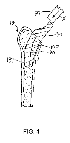
outer
surface within a conforming cavity defined by the cortical bone 715 of the
femur 710
and boundary or plane 726 and calculates or generates an extraction path for
the
initial inserted femoral stem 750. The initial implant 750 may be free to move
with
six-degrees of freedom in a series of small step movements, for example, as
indicated by arrows A, biased to a rigid transformation that minimizes the
collision of
the most points along the outer surface 755 of the initial implant 750 with
the inner
surface 715 of the cortical bone 714. The algorithm or program code identifies
all of
the points causing interferences for that incremental step and removes them
from
the initial implant 750, resulting in a resultant femoral stem 800 as shown in
FIG. 17.
The algorithm or program code also records the rigid transformation for each
-19-
CA 03137029 2021-10-14
WO 2020/214804 PCT/US2020/028499
incremental step such that such transformations can be re-integrated into an
insertion trajectory 835. The process may be repeated to generate an optimized
resultant patient specific femoral stem 800 having a shape that maximizes
cortical
contact when installed in the patient along the insertion trajectory 835. A
neck
component 810 may be generated and attachable or integral with femoral stem
800.
In some embodiments, the resultant femoral stem 800 includes asymmetric cross-
sections. In some embodiments, portions, such as portion 837, of the outer
surface
of outer surface of the resultant femoral stem 800, may match the
corresponding
contour and shape of the patient's inner cortical bone surface 715 of the
femur 10.
[0063] An embodiment for solving the problem of stability and insertability
of a
femoral sleeve component in a total hip replacement, for example, may be
through a
computer implemented method utilizing programming code in a recursive process,
whereby an implant is designed that maximizes cortical contact from a proximal
member along the long axis of the femur. Rather than calculating an insertion
path,
the present technique is directed to program code that begins with an initial
implant
representation. FIGS. 18-21 diagrammatically illustrate a computerized
process, for
example, implemented, by programming code for use in forming a patient
specific
femoral sleeve of a femoral component for total hip replacement, according to
an
embodiment of the present disclosure.
[0064] For example, FIG. 18 illustrates a proximal portion of a patient's
femur 910
having centralized cancellous bone 912 and peripheral cortical bone 914. For
example, data representing the proximal portion of the patient's femur 910 may
include three-dimensional data obtained by, for example, a Computed Tomography
(CT) scan, a Computerized Axial Tomography (CAT) scan, a Magnetic Resonance
Imaging (MRI) scan, or other suitable two-dimensional imaging or three-
dimensional
imaging or processing. A surgeon may input a proximal extreme location 917, a
distal extreme location 918, and a mid-location 919 of the desired patient
customized
femoral sleeve implant for the femur 910. Alternative, the proximal extreme
location
917, the distal extreme location 918, and the mid location 919 may be
determined
and generated by program code. Other features may be used of the patient's
femur
and/or used in conjunction with data representing the standard femoral stem
470
(FIG. 12) and the femoral neck implant 410 (FIG. 12) (e.g., superimposed) and
may
be determined and generated by program code.
- 20 -
CA 03137029 2021-10-14
WO 2020/214804 PCT/US2020/028499
[0065] In this approach, as shown in FIG. 19, a first plane 922 having an
orientation relative to the proximal femur may be generated at the mid
location 919
(FIG. 18), a second plane 923 having an orientation relative to the proximal
femur
may be generated at the mid location 919 (FIG. 18), and a third plane 924
having an
orientation relative to the proximal femur may be generated at the distal
location 924
(FIG. 18). The first plane and the second plane may correspond to the
resection
planes.
[0066] In some embodiments, the first and second planes may be normal or
perpendicular to each other, and the first plane and the third plane may
normal or
perpendicular to a femoral shaft axis. Alternatively, a surgeon may input
planes 922,
923, and 924, and the orientations thereof. In some embodiments, resection
planes,
such as first plane 922 and second plane 923 may be provided, e.g., by input
by a
surgeon, or based on or utilizing predetermined data.
[0067] As shown in FIG. 20, an initial implant or femoral sleeve 950 is
constructed. The initial implant 950 is generated between the mid location 919
and
the distal extreme location 918. The initial implant 950 may have an outer
surface
that corresponds to an inner surface 915 of the cortical bone 914, the first
plane 922,
and the third plane 924.
[0068] The computerized process includes the initial implant 950 having an
outer
surface within a conforming cavity defined by the cortical bone 915 of the
femur 910
and boundary or planes 922 and 924 and calculates or generates an extraction
path
for the initial inserted femoral stem 950. The initial implant 950 may be free
to move
with six-degrees of freedom in a series of small step movements, for example,
as
indicated by arrows B, biased to a rigid transformation that minimizes the
collision of
the most points along the outer surface 955 of the initial implant 950 with
the inner
surface 915 of the cortical bone 914. The algorithm or program code identifies
all of
the points causing interferences for that incremental step and removes them
from
the initial implant 950, resulting in a resultant femoral sleeve 1000 as shown
in FIG.
21. The algorithm or program code also records the rigid transformation for
each
incremental step such that such transformations can be re-integrated into an
insertion trajectory 1005. The process may be repeated to generate an
optimized
resultant patient specific femoral sleeve 1000 having a shape that maximizes
cortical
-21 -
CA 03137029 2021-10-14
WO 2020/214804 PCT/US2020/028499
contact when installed in the patient along the insertion trajectory 1005. A
passageway 1050 may be generated for receiving a standard femoral stem and
neck, such as femoral stem 470 (FIG. 12) and neck 410 (FIG. 12).
[0069] FIG. 22 illustrates a workflow 1100 that depicts certain aspects of
some
embodiments of the present disclosure for use in forming a patient specific
femoral
stem or femoral sleeve of a femoral component for total hip replacement. In
some
embodiments of the present disclosure, a program code 1110 (also referred to
as
one or more programs) executed by a processing circuit or hardware, obtains at
1120, by one or more processors, three-dimensional data representing a
proximal
femur of the patient having centralized cancellous bone and peripheral
cortical bone.
At 1130, three-dimensional data representing an initial implant having an
outer
surface disposed within and corresponding to the inner surface of the
peripheral
cortical bone of the proximal femur of the patient is generated, by the one or
more
processors, based on the three-dimensional data representing a proximal femur
of
the patient. At 1140, the three-dimensional data representing the initial
implant is
translated, by the one or more processors, from the three-dimensional data
representing the proximal femur of the patient. At 1150, three-dimensional
data
representing a patient specific femoral stem or sleeve having a modified outer
surface allowing for removal from the peripheral cortical bone along an
insertion/removal path without obstruction by the inner surface of the
cortical bone is
generated, by the one or more processors, based on the translation of the
three-
dimensional data representing the initial implant and the data representing
the
proximal portion of the femur of the patient having centralized cancellous
bone and
peripheral cortical bone..
[0070] In some embodiments of the present disclosure, the workflow 1100 may
further include program code for fabricating, by the one or more processors,
the
femoral stem or sleeve based on the three-dimensional data representing the
patient
specific femur.
[0071] In some embodiments of the present disclosure, the translating 1140
may
include program code for translating, by the one or more processors, the three-
dimensional data representing the initial implant a plurality of incremental
translations from the three-dimensional data representing the proximal femur
of the
- 22 -
CA 03137029 2021-10-14
WO 2020/214804 PCT/US2020/028499
patient, and wherein each of the plurality of incremental translation includes
a
plurality of different translations, and program code for selecting, by the
one or more
processors, one of the different translations based on the different
translation
requiring the least modification of the initial implant.
[0072] In some embodiments of the present disclosure, the translating 1140
may
include program code for translating, by the one or more processors, the three-
dimensional data representing the initial implant in a plurality of
incremental
translations from the three-dimensional data representing the proximal femur
of the
patient, and the generating may include program code for generating, by the
one or
more processors, the three-dimensional data representing the patient specific
femoral stem or sleeve based on the translating the three-dimensional data
representing the initial implant in the plurality of incremental translations.
[0073] In some embodiments of the present disclosure, the translating 1140
may
include program code for translating, by the one or more processors, the three-
dimensional data representing the initial implant in a plurality of
incremental straight
line translations from the three-dimensional data representing the proximal
femur of
the patient, and the generating may include program code for generating, by
the one
or more processors, the three-dimensional data representing the patient
specific
femoral stem or sleeve based on the translating the three-dimensional data
representing the initial implant in the plurality of incremental straight line
translations.
In addition, the translating 1140 may include program code for translating, by
the one
or more processors, the three-dimensional data representing the initial
implant along
a coronal plane from the three-dimensional data representing the proximal
femur of
the patient, and the generating may include program code for generating, by
the one
or more processors, the three-dimensional data representing the patient
specific
femoral stem or sleeve based on the translating the three-dimensional data
representing the initial implant along the coronal plane.
[0074] In some embodiments of the present disclosure, the translating 1140
may
include program code for translating and rotating, by the one or more
processors, the
three-dimensional data representing the initial implant from the three-
dimensional
data representing the proximal femur of the patient, and the generating may
include
program code for generating, via the processor, the three-dimensional data
- 23 -
CA 03137029 2021-10-14
WO 2020/214804 PCT/US2020/028499
representing the patient specific femoral stem or sleeve based on the
translating the
three-dimensional data representing the initial implant in the coronal plane.
[0075] FIG. 23 illustrates a hip arthroplasty system 1200 having a patient
specific
femoral stem component 1210, according to an embodiment of the present
disclosure. For example, a patient specific femoral stem component 1210 may be
designed and fabricated as described above. In this illustrated embodiment,
arthroplasty system 1200 may include an acetabular component 1220, a bearing
liner 1230, a femoral head 1240, a femoral neck 1250, and the patient specific
femoral stem component 1210.
[0076] FIG. 24 illustrates a block diagram of a computer system 1300, which
is
part of the technical architecture of the embodiments of the present
disclosure.
System 1300 may include a circuitry 1310 that may in certain embodiments
include a
microprocessor 1320. The system 1300 may also include a memory 1330 (e.g., a
volatile memory device), and storage 1340. The system 1300 may include a
program logic 1350 including code 1352 that may be loaded into or stored in
the
memory 1330, the storage 1340, and/or circuitry 1310, and executed by the
microprocessor 1320 and/or circuitry 1310. The various components may be
operably coupled directly or indirectly via a system bus or may be coupled
directly or
indirectly to other data processing systems and components. The program logic
1350 may include the program code discussed above in this disclosure for use
in
forming a patient specific femoral stem or femoral sleeve of a femoral
component for
total hip replacement.
[0077] As will be appreciated by one skilled in the art, aspects of the
technique
may be embodied as a system, method, or computer program product. Accordingly,
aspects of the technique may take the form of an entirely hardware embodiment,
an
entirely software embodiment (including firmware, resident software, micro-
code,
etc.) or an embodiment combining software and hardware aspects that may all
generally be referred to herein as a "circuit," "module" or "system".
[0078] It will be understood that each block of the flowchart illustrations
and/or
block diagrams, and combinations of blocks in the flowchart illustrations
and/or block
diagrams, can be implemented by computer program instructions. These computer
program instructions may be provided to a processor of a general purpose
computer,
- 24 -
CA 03137029 2021-10-14
WO 2020/214804 PCT/US2020/028499
special purpose computer, or other programmable data processing apparatus to
produce a machine, such that the instructions, which execute via the processor
of
the computer or other programmable data processing apparatus, create means for
implementing the functions/acts specified in the flowchart and/or block
diagram block
or blocks. Each block in the flowchart or block diagrams may represent a
module,
segment, or portion of code, which includes one or more executable
instructions for
implementing the specified logical function(s).
[0079] These computer program instructions, also referred to as software
and/or
program code, may also be stored in a computer readable medium that can direct
a
computer, other programmable data processing apparatus, or other devices to
function in a particular manner, such that the instructions stored in the
computer
readable medium produce an article of manufacture including instructions which
implement the function/act specified in the flowchart and/or block diagram
block or
blocks. For example, in a particular arrangement, a desktop or workstation
computer
may be employed using a commercially available operating system, e.g. Windows
,
OSX , UNIX or Linux based implementation.
[0080] The computer readable storage medium 1340 may be, for example, but
not limited to, an electronic, magnetic, optical, electromagnetic, infrared or
semiconductor system, apparatus, or device, or any suitable combination of the
foregoing. The storage 1340 may include an internal storage device, an
attached
storage device and/or a network accessible storage device. More specific
examples
(a non-exhaustive list) of the computer readable storage medium include the
following: an electrical connection having one or more wires, a portable
computer
diskette, a hard disk, a random access memory (RAM), a read-only memory (ROM),
an erasable programmable read-only memory (EPROM or Flash memory), an optical
fiber, a portable compact disc read-only memory (CD-ROM), an optical storage
device, a magnetic storage device, or any suitable combination of the
foregoing. In
the context of this document, a computer readable storage medium may be any
tangible medium that can contain or store a program for use by or in
connection with
an instruction execution system, apparatus, or device.
[0081] Computer program code for carrying out operations for aspects of the
present technique may be written in any combination of one or more programming
- 25 -
CA 03137029 2021-10-14
WO 2020/214804 PCT/US2020/028499
languages, including an object oriented programming language, such as Java,
Smalltalk, C++ or the like, and conventional procedural programming languages,
such as the "C" programming language, PHP, ASP, assembler or similar
programming languages, as well as functional programming languages and
languages for technical computing. The program code may execute entirely on
the
user's computer, partly on the user's computer, as a stand-alone software
package,
partly on the user's computer and partly on a remote computer or entirely on
the
remote computer or server. In the latter scenario, the remote computer may be
connected to the user's computer through any type of network, including a
local area
network (LAN) or a wide area network (WAN), or the connection may be made to
an
external computer (for example, through the Internet using an Internet Service
Provider). Furthermore, more than one computer can be used for implementing
the
program code, including, but not limited to, one or more resources in a cloud
computing environment.
[0082] Input/output or I/O devices 1360 (including, but not limited to,
keyboards,
displays, pointing devices, DASD, tape, CDs, DVDs, thumb drives and other
memory
media, etc.) can be coupled to the system either directly or through
intervening I/O
controllers. Network adapters may also be coupled to the system to enable the
data
processing system to become coupled to other data processing systems or remote
printers or storage devices through intervening private or public networks.
Modems,
cable modems, and Ethernet cards are just a few of the available types of
network
adapters.
[0083] Data relating to a patient, e.g., the patient's pelvis and hip, may
be created
by, or accessed from, a medical sensor device. For example, previous medical
scans of an extremity, such as those obtained from a computerized axial
tomography
(CAT or CT) or magnetic resonance imaging (MRI) scan may be stored in a
medical
record storage apparatus, in storage 1340, or accessed by system 1300. Such
patient data may include other data for a given patient (e.g. bone density,
type,
length, medical conditions etc.). By way of a non-limiting example, the
patient data
may include a scan data set containing a series of two-dimensional images
obtained
from the scanning device (e.g. CT scan slices). As such, the scan data set is
a 3D
dimensional representation of the scan data.
- 26 -
CA 03137029 2021-10-14
WO 2020/214804 PCT/US2020/028499
[0084] From the present disclosure, it will be appreciated that the
technique of the
present disclosure for design of patient specific femoral stem or femoral
sleeve
implants overcome the problems of conventional femoral stem or femoral sleeve
implants. The technique of the present disclosure may include program
algorithms
and code to pre-operatively simulate surgical insertion of the generic
implants or
customized patient specific femoral stem or femoral sleeve implants. The
present
disclosure overcomes the problems with population-based design, which require
both obtaining or access to large segmented data pools of CT scans, which is
extremely costly, and designing standardized implants, which is time
consuming,
costly, and labor intensive. Proper classification and treatment of the
population
classifications can also increase cost, for example, if higher degrees of
refinement
are sought on the population classifications, which necessitate both increased
analysis and number of discrete implants that need to be designed.
[0085] The technique of the present disclosure allows determining or
optimizing a
minimum size for the femoral stem or femoral sleeve implants, which overcomes
generic implants that tend to be longer and thinner and result in more trauma
to the
femur upon insertion.
[0086] From the present description, it will be appreciated that the
technique of
the present disclosure allows for pre-operative insertability analysis and
helps
facilitate the design of customize implants by simulating insertability. The
present
disclosure may be useful for simulating the insertion of both generic and
custom
implants as well as for the design of both generic and custom implants. The
present
disclosure may be used with surgical procedures that employ a surgical robot.
The
present disclosure may be useful for pre-operative simulations of a surgical
procedure.
[0087] From the present description, the technique of the present
disclosure
includes a computer implemented methods for simulating insertion of generic
and
custom orthopedic hip implants. Computer implemented methods include
simulating
the insertion of generic and custom implants and include simulating the
removal of
an inserted implant and developing an implant around an optimized insertion
trajectory.
- 27 -
CA 03137029 2021-10-14
WO 2020/214804 PCT/US2020/028499
[0088] As may be recognized by those of ordinary skill in the art based on
the
teachings herein, numerous changes and modifications may be made to the above-
described and other embodiments of the present disclosure without departing
from
the scope of the disclosure. The implants, screws, and other components of the
devices and/or apparatus as disclosed in the specification, including the
accompanying abstract and drawings, may be replaced by alternative
component(s)
or feature(s), such as those disclosed in another embodiment, which serve the
same, equivalent or similar purpose as known by those skilled in the art to
achieve
the same, equivalent or similar results by such alternative component(s) or
feature(s)
to provide a similar function for the intended purpose. In addition, the
devices and
apparatus may include more or fewer components or features than the
embodiments
as described and illustrated herein. Accordingly, this detailed description of
the
currently-preferred embodiments is to be taken as illustrative, as opposed to
limiting
the disclosure.
[0089] The terminology used herein is for the purpose of describing
particular
embodiments only and is not intended to be limiting of the disclosure. As used
herein, the singular forms "a", "an" and "the" are intended to include the
plural forms
as well, unless the context clearly indicates otherwise. It will be further
understood
that the terms "comprise" (and any form of comprise, such as "comprises" and
"comprising"), "have" (and any form of have, such as "has", and "having"),
"include"
(and any form of include, such as "includes" and "including"), and "contain"
(and any
form of contain, such as "contains" and "containing") are open-ended linking
verbs.
As a result, a method or device that "comprises," "has," "includes," or
"contains" one
or more steps or elements possesses those one or more steps or elements, but
is
not limited to possessing only those one or more steps or elements. Likewise,
a step
of a method or an element of a device that "comprises," "has," "includes," or
"contains" one or more features possesses those one or more features, but is
not
limited to possessing only those one or more features. Furthermore, a device
or
structure that is configured in a certain way is configured in at least that
way, but
may also be configured in ways that are not listed.
[0090] The present disclosure has been described with reference to the
preferred
embodiments. It will be understood that the architectural and operational
embodiments described herein are exemplary of a plurality of possible
arrangements
- 28 -
CA 03137029 2021-10-14
WO 2020/214804
PCT/US2020/028499
to provide the same general features, characteristics, and general apparatus
operation. Modifications and alterations will occur to others upon a reading
and
understanding of the preceding detailed description. It is intended that the
present
disclosure be construed as including all such modifications and alterations.
** * * *
- 29 -