Note : Les descriptions sont présentées dans la langue officielle dans laquelle elles ont été soumises.
CA 03137806 2021-10-22
- 1 -
Method for controlling a wind turbine
The present invention relates to a method for controlling a wind turbine. The
present
invention also relates to a wind turbine. The present invention additionally
relates to a
wind farm with multiple wind turbines.
Wind turbines are known, they generate electrical power from wind and feed it
into an
electrical supply grid. As a result, wind turbines can make a contribution to
the energy
supply, but they are increasingly also used for tasks of supporting the
electrical supply
grid. It should be particularly noted here that, of all the feeding
generators, wind turbines
are among those that can be controlled the quickest. Consequently, they can be
used
particularly for quick short-term changes of the power feed-in.
-io These good properties of wind turbines have increasingly been
recognized and are
increasingly also being used for grid support. Apart from the suitability of
wind turbines for
quick control, wind turbines can also perform supporting tasks, particularly a
quick
increase in power or reduction in power, but not to any desired level and/or
not in any
desired short time. It should be particularly noted that wind turbines always,
that is to say
if they are not assigned a corresponding store, can only feed into the
electrical supply grid
as much power as is possible on the basis of the prevailing wind and of course
the design
of the wind turbine.
For this reason, it is known to operate wind turbines at a deliberately cut-
back level, in
order to be able when required to increase their power feed-in by the cut-back
power
value.
Date recue/date received 2021-10-22
- 2 -
Apart from the fact that such a method has the effect that energy that can be
generated
from the wind is forfeited, such a method also does not however take into
account that
the power to be fed in from the wind turbine cannot be changed without putting
a load on
the wind turbine. Particularly quick power changes may constitute putting a
load on the
wind turbine that is unfavorable and can for example have unfavorable effects
on the
lifetime of the wind turbine. In other words, such loading can lead to a
shortening of the
lifetime of the wind turbine. Although there are proposals, accordingly such a
reduction of
the service life can be estimated, they do not prevent such a reduction of the
service life.
The German Patent and Trademark Office has searched the following prior art in
the
to priority application relating to the present application: DE 10 2017 112
936 Al, US 2017/0
328 342 Al, EP 2 354 541 Al, HEIER, Siegfried: Windkraftanlagen:
Systemauslegung,
Integration und Regelung [Wind turbines: system design, integration and
control], 3rd
revised and extended edition, Wiesbaden: Vieweg+Teubner, 2003, pp. 431-434 &
456-
462. - ISBN 978-3-663-07668-1, DE 10 2009 059 669 Al, DE 10 2011 100 981 Al,
US
2009 / 0 230 681 Al and DE 10 2016 120 700 Al.
The invention is therefore based on the object of addressing at least one of
the problems
mentioned. In particular, it is intended to propose a solution which limits or
reduces a
loading of the wind turbine arising due to demands for grid support. At least
it is intended
to propose an alternative solution to the solutions known so far.
According to the invention, a method for controlling a wind turbine is
proposed.
Assumed here is a wind
turbine which is intended for feeding electrical power into an electrical
supply grid and has
a tower with a nacelle arranged rotatably on it. The wind turbine additionally
has an
aerodynamic rotor, which can be driven by wind, and a generator, which is
coupled to the
aerodynamic rotor and is intended for generating electrical power from wind.
Also
provided for this purpose is a power unit for controlling the generator for
controlling
electrical power output by the generator.
The generator is driven, directly or indirectly, by the aerodynamic rotor, in
order thereby to
generate electrical power from wind. Also provided is a power unit, for
controlling the
generator for controlling electrical power output by the generator.
Consequently, the
electrical power output by the generator can be controlled by way of the power
unit. For
this purpose, an active rectifier, which consequently rectifies the stator
current of the
Date recue/Date received 2023-05-03
CA 03137806 2021-10-22
- 3 -
generator, may particularly be provided. The control of the stator current
consequently
also allows the wind turbine to be controlled. At least, as a result an output
power of the
wind turbine can be controlled.
Furthermore, a feed-in unit for feeding the electrical power output by the
generator or part
thereof into the electrical supply grid is also provided.
The present invention is consequently based on these elements of a wind
turbine.
Building on this, the method comprises the following steps.
The wind turbine is controlled such that, in normal operation, an electrical
feed-in power is
fed into the electrical supply grid in dependence on the wind. Normal
operation is to this
extent operation in which no grid supporting demands are made. Consequently,
the wind
turbine feeds in in so-called grid-parallel operation, in which it therefore
feeds in as much
power as is possible on the basis of the prevailing wind and of course the
design of the
wind turbine.
It is also proposed that the electrical feed-in power is changed in dependence
on a grid
state or a grid demand of the electrical supply grid. For example, it may be
provided that
the feed-in power is reduced with increasing grid frequency, in any event as
soon as the
grid frequency has exceeded a predetermined limit value. In this case, the
electrical feed-
in power is changed in dependence on a grid state. If this frequency-dependent
power
reduction is a stipulation of the electrical supply grid, the electrical feed-
in power is
consequently also changed in dependence on an at least indirect grid demand.
However, it also comes into consideration that a current and specific grid
demand must
be met, accordingly for example the electrical supply grid or its operator
expressly
requires the reduction of the fed-in power by a percentage.
In this respect it is thus also proposed that the changing of the electrical
feed-in power is
guided such that a specifiable mechanical, in particular momentary, loading
limit of the
wind turbine is maintained. The wind turbine therefore does not directly
implement a
required change in the power fed in, whether it is dependent on a grid state
or dependent
on a specific demand for changing the power, but guides the changing of the
electrical
feed-in power. The changing of the electrical feed-in power is in this case
guided such
that the specifiable mechanical loading limit of the wind turbine is
maintained. Such a
mechanical loading limit may also be or comprise a set of multiple individual
loading
limits.
Date recue/date received 2021-10-22
CA 03137806 2021-10-22
- 4 -
This is based particularly on the idea that for example an abrupt increase in
the power fed
in is only possible by an abrupt increase in the torque. It does not matter
too much here
whether the torque has actually been increased directly, or the power output
by or taken
from the generator increases abruptly, which has an abrupt increase in the
torque as a
consequence.
In any event, the limiting of the specifiable mechanical power may
particularly take place
by a respective power demand not being passed on unchecked or unfiltered to
the wind
turbine, in particular to the generator, for implementation. Particularly in
the case of a
desired jump in power, which is therefore desired by the electrical supply
grid, this is
passed on in a somewhat lessened form to the generator for implementation. For
example, the use of a limitation to a flank for changing the power comes into
consideration, or such a power demand can be passed via a dynamic filter. In a
simple
case, such a dynamic filter may be a filter with simple lowpass
characteristics, such as for
example a delay element of the first order or second order.
As a result, a jump in power, and an accompanying loading of the wind turbine,
can be
avoided by a simple checking of the filtering of the specified value for the
changing of the
power.
It should be noted that unhindered passing on of an abrupt change in power, to
keep to
this example, may lead to an abrupt change in the generator torque, and that
leads
directly to mechanical loading of the generator. Such mechanical loading of
the generator
then possibly likewise affects the rotor blades of the rotor of the wind
turbine. Such a
jump in torque may also have an effect on the mounting of the generator on a
machine
carrier of the wind turbine.
Other changes in power than the jump in power mentioned by way of example also
come
into consideration however for such undesired loading, which according to the
invention is
now avoided, such as for example changes in the power that are not abrupt but
nevertheless very quick.
Which changes in torque and/or power lead to which mechanical loadings, or to
which
level of mechanical loading, can be recorded in advance in simulations.
However, on-site
measurements in which such quick changes in power and/or changes in torque are
carried out also come into consideration. The resultant loading may for
example be
recorded by strain gages on the rotor blades or by strain gages on other
loaded elements,
Date recue/date received 2021-10-22
CA 03137806 2021-10-22
- 5 -
such as for example the rotor hub. It is preferably ensured that only a few
such
measurements are carried out, and consequently few required instances of
inducing
corresponding loading. Alternatively, such measurement may be carried out with
very low
loading values and then be projected by calculation, in particular
extrapolated, to
correspondingly high loading.
It should be emphasized that the proposal concentrates on changing the
electrical feed-in
power. It is therefore checked to what extent the changing of the electrical
feed-in power
leads to mechanical loading, and correspondingly the changing of the
electrical feed-in
power is then carried out such that the specifiable mechanical loading limit
is maintained,
-io in particular carried out with such gradual changes over time. The
specifiable mechanical
loading limit may also be referred to as the specified mechanical loading
limit.
According to one embodiment, it is proposed that at least one limit gradient
is specified
for changing the feed-in power. Such a limit gradient is a maximum, in terms
of amount,
change over time of a power value, particularly a power value of an electrical
power
generated by the generator. The limit gradient may also be a maximum, in terms
of
amount, change of a generator torque to be controlled. In a graphically
illustrative form,
such a limit gradient consequently forms a flank rising with time, which must
not be
overshot by the corresponding power or the corresponding generator torque, and
a falling
flank, which must not be undershot by the corresponding power or the generator
torque to
be controlled. It is consequently proposed not to specify the corresponding
power or the
corresponding generator torque with regard to its variation, but to limit it
with regard to its
variation.
If therefore the changing of the electrical feed-in power in dependence on the
grid state or
in dependence on the grid demand leads to a changing of the power or to a
changing of
the generator torque which does not overshoot the limit gradient, in terms of
amount, no
change occurs. If, however, the changing of the electrical feed-in power would
require a
greater change, in terms of amount, the limit gradient would be reached and as
a result
the changing would be limited. This ultimately achieves the effect that
changes that are
too great or too quick are not passed on to the generator, and consequently
changes that
are too great or quick are not implemented. A mechanical loading limit of the
wind turbine
is thereby maintained.
The already mentioned investigations in advance, which may determine a link
between
changes in power and resultant loadings, consequently allow the mechanical
loading to
Date recue/date received 2021-10-22
CA 03137806 2021-10-22
- 6 -
be specified and a corresponding limit gradient to be chosen on the basis of
the recorded
link.
Preferably, the limit gradients are variable. Particularly, they may be
specified situation-
dependently. For example, a wind turbine in part-load operation, when the wind
is
therefore so weak that the wind turbine cannot reach its rated power, may
possibly only
be mechanically loaded by a changing of the feed-in power to a lesser extent
than a wind
turbine that is feeding in in full-load operation, which is therefore operated
with
correspondingly stronger wind.
Preferably, the limit gradient may also be varied for one and the same
operation, in that a
-io strong increase is allowed at the beginning, but is for example already
reduced a few
seconds later, that is to say for example 3, 4 or 5 seconds later. This is
based on the idea
that an initially short quick increase in power leads to mechanical loading
that is still
allowable, whereas the additional mechanical loading would however be exceeded
if a
correspondingly great change of the feed-in power were continued to be
allowed.
It also comes into consideration that mechanical loading only occurs due to an
oscillation.
Also such an oscillation can be prevented by specifying a corresponding limit
gradient. To
this extent it should be noted that a limitation of the change in power or a
change in
generator torque is a non-linear function. The effect consequently depends on
the
amplitude. According to the limited amplitude, this can possibly cause
oscillations, and
conversely such oscillations can be prevented by correspondingly specifying
the limit
gradient. It also comes into consideration here to check by investigations in
advance such
as simulations by which limit gradients such oscillations or other
oscillations can be
prevented or limited.
According to one embodiment, it is proposed that a generator torque of the
generator is
controlled by way of a setpoint torque value, the setpoint torque value being
passed via a
filter element, for reducing oscillation and/or for avoiding excitement of
generator
oscillation, the filter element being configured in particular as a lowpass
filter and/or as a
delay element, in particular as a linear delay element of the first or second
order.
To this extent, a special pre-filtering for the controlling of the generator
is proposed. Such
a filter element may also be referred to as pre-control. The filter element
prevents that a
jump in the setpoint value of the setpoint torque value is implemented
directly in the
generator control. As a result, particularly a surge in the generator, which
could excite an
Date recue/date received 2021-10-22
CA 03137806 2021-10-22
- 7 -
oscillation in the generator, can also be avoided. The filter element avoids
such a surge,
and consequently avoids such an excitement of an oscillation or can also serve
for
reducing oscillation.
The use of a lowpass filter consequently has the effect that particularly
higher frequencies
are removed from the setpoint torque value. Particularly the use of a linear
lowpass filter,
such as a linear delay element of the first or second order, makes a dynamic
consideration possible, in particular also consideration in the frequency
domain. As a
result, eigenvalues or a resonant frequency of the generator can be
specifically taken into
account.
to The use of the limit gradient and a filter element, which may also be
referred to
synonymously as a filter, can also be combined. In particular, such a
combination may
take the form that first a limitation of the power and/or of the generator
torque is
performed by the limit gradient and then the signal thus limited is processed
further. The
signal thus limited may already represent a limitation of a setpoint torque
value and then
be passed as such via the filter element. Or, particularly if it concerns an
amount of
power, the limited signal may be transformed into a setpoint torque value and
the
resultant setpoint torque value may be passed via the filter element.
According to one embodiment, it is proposed that the changing of the
electrical feed-in
power is controlled such that, following a generator torque exceeding a torque
limit value
predetermined in terms of amount, a further generator torque exceeding the
predetermined torque limit value is suppressed for a predetermined recovery
time period
or is limited to the torque limit value. Consequently, initially an excessive
generator torque
is allowed. If a further generator torque exceeding the torque limit value
then occurs, this
is no longer allowed. Depending on the situation, this may mean that it is
generally not
allowed, but is preferably limited to the torque limit value. This preferably
takes place for 5
to 30 seconds. Preferably, the generator torque exceeding the predetermined
torque limit
value is also allowed for a predetermined time period and this time period may
correspond to the recovery time period.
It has however been recognized that the underlying problem may be that the
generator
and the mechanical structure behind it may start oscillating due to a number
of great
generator torques in series. This fundamentally obviates the problem that the
generator
torque is permanently too great. It should also be noted here that such a high
generator
Date recue/date received 2021-10-22
CA 03137806 2021-10-22
- 8 -
torque, which may also be referred to synonymously as a generator moment,
occurs
particularly due to a change in power.
Such a high generator torque may occur particularly if, as a result, flywheel
energy, that is
to say kinetic energy, is to be removed from the rotor of the wind turbine. If
a great
generator torque thereby occurs, this means that the generator is also
strongly braked. If
this great generator torque were therefore to occur for a long time, for
example for one
minute, this may lead to such strong braking of the generator, and
consequently the rotor,
of the wind turbine that it may come to a standstill. Such a situation is also
unfavorable
and usually undesired; however, there is then no longer high mechanical
loading.
to The present invention however concerns reducing or limiting a mechanical
loading and, to
remain with the example mentioned, this may occur particularly as a result of
kinetic
energy being removed from the rotor of the wind turbine in the short term and
for a short
time, for example for 5 seconds, by a correspondingly high generator torque.
This may be
the case for example when the frequency in the electrical supply grid
fluctuates and the
wind turbine tries to counteract it by briefly increased power feed-in.
If therefore the generator torque has been very high for a brief moment, such
as the 5
seconds mentioned by way of example, it can be assumed that no additional
energy is
demanded in the following 5 seconds, on account of the frequency oscillation
in the
electrical supply grid, and the generator torque has correspondingly dropped
again.
Likewise 5 seconds later, to keep with the above example, a high power demand
may
then occur once again, with a corresponding resultant high generator torque.
Therefore,
great changes of torque potentially occur in the 5 second cycle. Depending on
the
frequency of these great changes of torque, they may lead to the generator or
the
generator rotor system starting to oscillate. To avoid this, the mentioned
recovery time
period is provided. As a result, a rapid succession of great generator torques
is avoided.
According to a further embodiment, it is proposed that the changing of the
electrical feed-
in power is controlled such that, in the case of a decaying oscillation of the
generator
torque with a maximum amplitude that exceeds the predetermined amplitude limit
value,
a further generator torque pulse with at least half the amplitude of the
amplitude limit
value is avoided. If, therefore, the generator torque oscillates, which can be
accompanied
by a mechanical oscillation of the generator and the rotor, any further
generator torque
pulses are suppressed. If these generator torque pulses are small, to be
specific less
Date recue/date received 2021-10-22
CA 03137806 2021-10-22
- 9 -
than half the amplitude of the amplitude limit value, it is possible to
dispense with this
suppression.
It can as a result be prevented that such decaying, but still existing
oscillation of the
generator torque is indeed excited again. It is proposed in this respect that
this
suppression of such further generator torque pulses is carried out until the
decaying
oscillation has decayed to an amplitude that lies below a predetermined
amplitude decay
value. This amplitude decay value is preferably chosen to be less than 25% of
the
amplitude limit value.
There is therefore at most still an oscillation with an amplitude of a quarter
of the
io amplitude limit value and, in the case of such a small value of a
quarter, it can be
assumed that the oscillation is considered to have essentially decayed.
Alternatively, a decay time may also be chosen, so that therefore the
suppression of
further generator torque pulses of a corresponding level is only carried out
until a
predetermined decay time has elapsed. Such a decay time preferably lies in the
range
from 5 to 30 seconds. It has been recognized here that ¨ depending on the
generator - a
generator oscillation has decayed, which even in the case of generators of low
oscillating
frequency can be assumed at 30 seconds. Of course, depending on the generator,
a
different decay time may also be chosen.
According to one embodiment, it is proposed that a generator control circuit,
which
comprises at least the generator and the power unit, is formed for controlling
the
generator. It is also proposed that control dynamics, in particular
eigenvalues and/or
poles, are specified for the generator control circuit, and the specifying of
the control
dynamics, in particular the eigenvalues or poles, takes place such that the
specifiable
mechanical loading limit of the wind turbine can be maintained.
When using a generator control circuit of such a configuration, the torque can
consequently be specified as a setpoint value and to this extent form the
input variable for
the control circuit. The current actual value of the torque value is
subtracted from this and
the resultant system deviation is passed via a controller, the dynamics of
which can be
specified, or by way of which the dynamics of the control circuit can be
specified.
The result of such a controller may then be a manipulated variable. The
manipulated
variable may be passed to the power unit for implementation. The manipulated
variable
Date recue/date received 2021-10-22
CA 03137806 2021-10-22
- 10 -
may be for example an exciter current to be set if the generator is designed
as a
separately excited synchronous generator. By way of this exciter current, the
generator
torque can be set, or at least fundamentally changed.
This is however only one, particularly graphic example. According to another
example,
the setting of the generator torque may take place by way of an active
rectifier. The active
rectifier may for this purpose control the stator current output by the
generator, and
thereby the power output by the generator. As a result, in turn the generator
torque can
be set.
With the generator control circuit, a power of the generator, to be specific
an output
to power, can be set directly. In this case, there is therefore a setpoint
value for the output
power that is to be set. This can be compared with an actual value of the
output power,
that is to say the generator power, and the resultant system deviation can be
passed via
the controller, which calculates a manipulated variable from it and passes it
to the power
unit for implementation.
It has consequently been recognized that such dynamics that can also influence
mechanical loading, and as a result can prevent mechanical overloading, can be
specified by way of this generator control circuit. Particularly, the
parameterization of this
generator control circuit can be used to make the control of the generator so
slow that
generator torques that are too high, and consequently mechanical loadings that
are too
high, are avoided.
The use of such a generator control circuit can also be combined with the
proposal of the
limit gradient and/or the proposal of the upstream filter element. The
parameterization of
the generator control circuit may possibly have to be adapted to it.
According to one embodiment, it is proposed that the generator control circuit
includes
mechanical elements or takes into account mechanical properties, to be
specific the
aerodynamic rotor, in particular its moment of inertia, and/or at least one
blade
eigenfrequency and additionally or alternatively the tower with the nacelle,
in particular at
least one eigenfrequency of an oscillation of the tower with the nacelle.
It is consequently proposed that these dynamics that are caused by the
mechanical
properties are taken into account in the generator control circuit. This is
particularly
reflected in the parameterization of the control circuit. It is particularly
known that not only
Date recue/date received 2021-10-22
CA 03137806 2021-10-22
- 1 1 -
the aerodynamic rotor and the rotor blades but also the interrelationship
between the
tower and then nacelle can in each case have an eigenfrequency and/or
corresponding
complex conjugate eigenvalues. Such properties may be known or determined in
simulations. These properties can then be introduced into the generator
control circuit,
particularly into the parameterization of the generator control circuit.
According to one embodiment, it is proposed that the generator control circuit
includes a
property or a behavior of the electrical supply grid, in particular that an
eigenfrequency
and/or an oscillation of the electrical supply grid is included. A property,
in particular an
eigenfrequency, of the electrical supply grid is consequently a general
property that may,
but does not have to, lead to an oscillation. If it leads to an oscillation,
the associated
frequency is in that case known. This frequency is also of importance for the
question of
its excitation, and it is proposed precisely for this purpose that it is taken
into account in
the generator control circuit.
Additionally or alternatively, a current behavior, in particular a currently
existing
oscillation, of the electrical supply grid may be recognized and then can be
taken into
account directly in the control circuit. In this case, the control circuit
could be adaptively
designed, in order to take into account such current behavior, in particular a
current
frequency of an oscillation. Alternatively, the control circuit may be
designed so robustly
that it can cover a spectrum of possible frequencies. Such a spectrum may be
the result
of empirical values.
According to one embodiment, it is proposed that a mechanical model of the
wind turbine
is taken into account in the changing of the electrical feed-in, in order to
guide the
changing of the electrical feed-in such that a specifiable, in particular
momentary,
mechanical loading limit of the wind turbine can be maintained. It is proposed
with
particular preference that the mechanical model is contained in the generator
control
circuit, or at least is taken into account there.
Such a mechanical model modulates particular relationships between mechanical
movements, mechanical bending distortions and mechanical forces, therefore
maps
them. This preferably includes the modulation of a relationship between the
generator
torque occurring, which consequently also acts on the rotor, and the resultant
movement
of the rotor and also other forces occurring on the rotor. It may thus include
an
Date recue/date received 2021-10-22
CA 03137806 2021-10-22
- 12 -
acceleration behavior of the rotor dependent on such a torque, including a
resultant
bending distortion of the rotor blades, the forces resulting from that on the
rotor blades
and in particular on the pitch bearing at which the rotor blades are fastened
to the hub of
the rotor, and possible oscillations occurring.
If it is therefore planned for example to increase the electrical feed-in
power, it can be
deduced how in return the generator torque increases. This generator torque,
or its likely
increase, may then form an input variable for the mechanical model and,
depending on
this, it can be recognized which mechanical loads are to be expected. This can
then be
compared with the specifiable mechanical loading limit and, depending on this,
the
to changing of the electrical feed-in power can be adapted as required,
that is to say in
particular reduced or slowed down as required.
These aspects can be taken into account by the mechanical model being
contained in the
generator control circuit. For example, a mechanical loading that is
recognized by the
mechanical model can change a control gain in the generator control circuit by
way of a
control stipulation. For this, the mechanical model may be directly
incorporated in the
generator control circuit. It may however also be that the mechanical model is
taken into
account in the generator control circuit by the input variable of the
generator control
circuit, that is to say the setpoint value for the generator torque or the
setpoint value for
the generator power to be set, being adapted dependent on the mechanical
model.
According to one embodiment, it is proposed that an oscillation detecting
means is
provided, for detecting at least one oscillation of the wind turbine, in
particular for
detecting mechanical oscillations and/or oscillations of the generator, the at
least one
detected oscillation being used for guiding the changing of the electrical
feed-in power
such that the specifiable mechanical loading limit of the wind turbine can be
maintained.
It is consequently proposed here as a variant that mechanical oscillations
and/or
oscillations of the generator are directly detected. Mechanical oscillations
of the wind
turbine and/or oscillations of the generator are at the forefront here.
Mechanical
oscillations of the wind turbine may particularly also be oscillations of the
rotor,
particularly in the direction of rotation. Such oscillations may be caused for
example by
elasticities of the rotor blades. However, oscillations in the longitudinal
direction of a rotor
axis of rotation, and consequently generator axis of rotation, also come into
Date recue/date received 2021-10-22
CA 03137806 2021-10-22
- 13 -
consideration. Such oscillations can also be caused by changes in power, and
consequently changes in load.
It is likewise proposed to detect oscillations of the generator. Such
generator oscillations
may also be mechanical oscillations. However, it also comes into consideration
that a
torque oscillation is detected, and this can be detected electrically.
However, such a
torque oscillation then also often causes a mechanical oscillation. It is
particularly
proposed here to use the method for a gearless wind turbine. In this case,
oscillations of
the generator also act directly, to be specific without an intermediate gear
mechanism, on
the rotor, and similarly oscillations of the rotor act directly on the
generator.
to Such an oscillation detecting means may be for example an acceleration
sensor, which
can detect particularly, but not only, oscillations of the rotor, and
consequently of the
nacelle, of the wind turbine in the longitudinal direction of the rotor axis.
Also coming into
consideration are strain gages, which can detect oscillations on the basis of
strains on the
tower of the wind turbine and/or which can recognize oscillations of the rotor
blades when
attached correspondingly, if for example they are arranged at a region at the
root of the
rotor blades. A rotor position sensor may also be used for oscillation
measurement, if a
variation over time of the rotor position thus detected, which may also be
referred to as
the rotary position of the rotor, is evaluated.
Torque oscillations of the generator may either be derived from the control of
the wind
turbine, which often has knowledge of the current output power of the
generator. Or else
oscillations of the torque may be detected by the specific current sensor as
an oscillation
detecting means. This is also only another example of an oscillation detecting
means.
Optical sensors, which can record movements of elements, also come into
consideration
as another example.
According to one embodiment, it is proposed that a limiting filter is proposed
for
controlling the generator, in particular for controlling it by way of a
setpoint torque value,
in order to limit a control signal, in particular to be specific the setpoint
torque value, to a
predetermined limit amplitude in a specified frequency range.
Preferably, the limit amplitude is in this case specified as a frequency-
dependent variation
in amplitude. This is particularly based on the idea that relationships
between the torque
of the generator and the resultant mechanical loadings are already known. Such
relationships may be detected in advance by measurements or by simulations.
Here, the
specified frequency range may also be defined and correspondingly specified,
that is to
Date recue/date received 2021-10-22
CA 03137806 2021-10-22
- 14 -
say also the associated limit amplitude, which as a result may be
predetermined. Then,
the maintenance of the specifiable mechanical loading limit can be achieved by
this
limiting filter in an easy and in particular also quick way. Particularly,
with this proposal
there is no need for any feedback of measurements.
Particularly in the case of investigations in advance, whether on an actual
system or by
means of simulations, a frequency dependence can also be recognized and
recorded in
principle and also quantitatively. Accordingly, the limit amplitude may be
different
depending on the frequency. A frequency-dependent variation in amplitude may
in this
case also particularly relate to the use for example of a jump signal as a
setpoint torque
value. According to the teaching of Fourier, such a jump signal is made up of
different
frequency components and precisely that can be taken into account by
specifying a
frequency-dependent variation in amplitude. It possibly comes into
consideration that
such a limit amplitude is designed as a corresponding frequency-dependent
function or a
frequency-dependent limiting system. A corresponding frequency-dependent
filter
particularly comes into consideration here.
Preferably, the wind turbine has a synchronous generator, it being of a
gearless
configuration. It is also provided that the power unit has a rectifier and a
stepup converter,
or that it has a controlled rectifier. If it has a controlled rectifier, the
stepup converter is not
needed.
For this use of a synchronous generator, it is thus envisaged to use the
stepup converter
or the controlled rectifier for controlling the generator for controlling the
power output by
the generator or for controlling the generator torque. Both with the stepup
converter and
the controlled rectifier, in each case a stator current of the generator can
be controlled.
This stator current is to this extent an output current of the synchronous
generator.
Consequently, the output power of the synchronous generator can be controlled
by the
control of this stator current. With corresponding conversion and account
taken of the
speed of the rotor of the generator, similarly a torque can be derived from
the stator
current or a torque of the generator can be set by way of the stator current.
The generator
torque can consequently be specified as desired, and consequently also a
torque acting
on the rotor.
In the case of a preferably used gearless wind turbine, the torque of the
rotor can
consequently be specified directly. Particularly if the rotor torque is a
critical factor with
regard to the specifiable mechanical loading limit, a corresponding loading
can be directly
Date recue/date received 2021-10-22
CA 03137806 2021-10-22
- 15 -
influenced, and possibly set and limited, by way of this controlling of the
synchronous
generator. Even if other elements or further elements are relevant with regard
to the
specifiable mechanical loading limit, such as for example a bending and/or
oscillation of
the rotor blades, this can also be influenced well by way of controlling the
electrical power
or generator torque output by the generator using the power unit mentioned.
Preferably, the synchronous generator is designed as a separately excited
synchronous
generator and the power unit then comprises an exciter generator, in
particular a DC
chopper, in order thereby to control an exciter current of the synchronous
generator. As a
result, the excitation of the synchronous generator can be controlled, and
consequently a
control of the generator torque can be carried out well. This also allows the
output
electrical power of the generator to be controlled. Correspondingly, the power
unit is
thereby provided with a good, and in particular further possibility of setting
the power
and/or the generator torque, and consequently of influencing the mechanical
loading.
According to the invention, a wind turbine that is designed for feeding
electrical power into
an electrical supply grid is proposed. It comprises
- a tower with a nacelle arranged rotatably on it,
- an aerodynamic rotor, which can be driven by wind,
- a generator, which is coupled to the aerodynamic rotor and is
intended for
generating electrical power from wind,
- a power unit for controlling the generator for controlling electrical
power output by
the generator and/or for controlling a generator torque and
- a feed-in unit for feeding the electrical power output by the
generator or part
thereof into the electrical supply grid,
- a control unit for controlling the wind turbine such that, in
normal operation, an
electrical feed-in power is fed into the electrical supply grid in dependence
on the
wind, the control unit being prepared
- to control a changing of the electrical feed-in power in
dependence on a grid state
and/or a grid demand of the electrical supply grid,
- the changing of the electrical feed-in power being guided such
that a specifiable
mechanical, in particular momentary, loading limit of the wind turbine is
maintained.
The wind turbine is consequently designed in the way that has already been
explained
above in connection with the method according to the invention for controlling
a wind
turbine.
Date recue/date received 2021-10-22
CA 03137806 2021-10-22
- 16 -
The control unit of the wind turbine may be designed particularly as a process
computer
and in this case particularly be coupled to the power unit and the feed-in
unit. Preferably,
the control unit to this extent controls both the power unit and the feed-in
unit. However, it
also at least partially comes into consideration that the feed-in unit is
controlled indirectly
by the power unit.
Such control may be designed such that, by controlling the electrical power
output by the
generator, or indirectly by controlling the generator torque, the power unit
also controls a
supply of power, and over time a supply of energy, to the feed-unit. Part of
the control of
the feed-in unit may then be configured such that the feed-in unit controls
the feeding into
the electrical supply grid dependent on the power or energy that it receives
from the
power unit or through the control of the power unit.
The control unit may also be connected to a detecting unit for detecting at
least one grid
state. Particularly, the voltage in the electrical supply grid, or a voltage
representative of it
at the output of the feed-in unit, may be detected here, and in addition the
fed-in current
and/or the fed-in power.
The detecting of the voltage of the electrical supply grid in this case
comprises in addition
to a voltage amplitude also a frequency of the electrical voltage.
Furthermore, a phase
position is detected, in particular a phase position of the electrical voltage
with respect to
the fed-in electrical current. A fed-in reactive power component can also be
derived from
it. A need for change of the power to be fed into the electrical supply grid
can also be
deduced from these values, particularly the detected grid frequency and/or a
change of
the grid frequency.
This need for change may then be evaluated in the control unit and, dependent
on it,
again the controlling of the generator may be controlled, to be specific by
way of
controlling the power unit. The control unit may receive information
concerning the grid
state and otherwise also from the feed-in unit if the latter detects the
mentioned grid
variables or grid states or some of them.
The control unit may also include the specifiable mechanical loading limit.
This may also
be specified in the control unit. To the extent to which it is specified
dependent on a
stipulation and/or dependent on input variables, such a specification may also
be carried
out in the control unit. In this case, the mechanical loading limit may also
be calculated
there or determined in some other way. For absolute values of the specifiable
mechanical
Date recue/date received 2021-10-22
CA 03137806 2021-10-22
- 17 -
loading limit, it also comes into consideration that they are stored in
advance in the
control unit, in particular at the factory. It nevertheless also comes into
consideration that
they are occasionally renewed.
According to one embodiment, it is provided that the wind turbine, in
particular the control
unit, is prepared for carrying out a method for controlling a wind turbine
according to at
least one embodiment described above.
For this purpose, the control unit may be designed correspondingly. The
mentioned
connections between the control unit and the power unit and also the feed-in
unit may
also be included in such a design. A connection of a measuring unit for
recording grid
states, in particular electrical variables of the electrical supply grid, may
also be included
in this preparation of the control unit for carrying out the method mentioned.
By means of a mechanical model of the wind turbine, mechanical loads can be
estimated,
in particular estimated in advance. This mechanical model may also be designed
and
used in the way explained above in connection with embodiments of the method
for
controlling a wind turbine.
According to the invention, a wind farm with multiple wind turbines is also
proposed. In
this case it is provided that the wind turbines, at least some of them, are
designed
according to at least one embodiment described above of a wind turbine.
Here it particularly comes into consideration that the wind turbines feed into
the electrical
supply grid together at a grid connection point, and thereby change this
electrical feed-in
power that is fed in altogether in dependence on a grid state and/or a grid
demand, a
changing of the electrical feed-in power of each individual wind turbine in
this case being
controlled such that a specifiable mechanical loading limit of each individual
wind turbine
is maintained. In this way it can be achieved that the power fed in altogether
at the grid
connection point can be adjusted better in dependence on the grid state or the
grid
demand.
According to one embodiment, it is proposed that the wind farm is connected to
the
electrical supply grid at a grid connection point in order to feed an
electrical farm power
into the electrical supply grid. The electrical farm power is essentially the
sum of all the
electrical feed-in powers of the wind turbines of the wind farm at the
respective moment.
Date recue/date received 2021-10-22
CA 03137806 2021-10-22
- 18 -
Furthermore, a central farm control is provided for the wind farm, in order to
coordinate
the wind turbines such that the electrical farm power is fed into the
electrical supply grid
at the grid connection point, in particular while taking into account the
respective
specifiable loading limit of each wind turbine. Consequently, the central farm
control
coordinates the wind turbines in any event with regard to their electrical
feed-in power.
For this, the central farm control may give an individual setpoint value for
the electrical
feed-in power to each wind turbine. The wind turbine then sets the
corresponding
electrical feed-in power and the sum of all of these electrical feed-in powers
is then
essentially the electrical farm power. If, however, a changing of the
electrical feed-in
power is required, or such changing is announced, each wind turbine may return
a signal
to the central farm control in order to indicate to the central farm control a
limitation of the
possible changing of the feed-in power.
Dependent on this, the central farm control can then correspondingly adapt how
the
electrical farm power is divided up among the wind turbines, in that for
example a wind
turbine that has not yet met a specifiable mechanical loading limit takes over
part of the
power that another wind turbine cannot deliver at the moment because of a
mechanical
loading limit.
It also comes into consideration that, whenever a desired changing of the
electrical farm
power is not achievable because of the specifiable mechanical loading limits
of all the
wind turbines, then a new electrical farm power that can be achieved is
specified.
It comes into consideration in this respect that it is proposed according to
one
embodiment that the central farm control transmits to a grid operator that is
operating the
electrical supply grid information concerning to what extent the changing of
the electrical
farm power can be implemented. The electrical supply grid or its grid operator
can then
adapt to this situation.
The invention is now described in more detail below by way of example on the
basis of
exemplary embodiments with reference to the accompanying figures.
Figure 1 shows a wind turbine in a perspective representation.
Figure 2 shows a wind farm in a schematic representation.
Date recue/date received 2021-10-22
CA 03137806 2021-10-22
- 19 -
Figure 3 shows a generator controlling in a schematic representation.
Figure 1 shows a wind turbine 100 with a tower 102 and a nacelle 104. Arranged
on the
nacelle 104 is a rotor 106 with three rotor blades 108 and a spinner 110.
During
operation, the rotor 106 is set in a rotary motion by the wind, and thereby
drives a
generator in the nacelle 104.
Also provided is a feed-in unit 101 for feeding electrical power output by the
generator
into an electrical supply grid 120. For this purpose, the feed-in unit outputs
a three-phase
alternating current, which can be fed into the electrical supply grid 120 by
way of a grid
transformer 116 at the common grid connection point 118.
Also indicated in Figure 1 is a current pickup 103 and a voltage pickup 105,
which can
also together form a measuring device. The current that can consequently be
detected
and the voltage that can consequently be detected can be used as an input
signal for the
feed-in unit 101. As a result, grid states such as the grid frequency or the
grid voltage can
also be detected. For detecting the grid voltage, the transmission behavior of
the grid
transformer 116 may be taken into account. It is also possible by the current
pickup 103
and the voltage pickup 105 to detect the phase position of the current and
voltage in
relation to one another, and consequently also detect fed-in active power and
fed-in
reactive power, or thereby also a power factor. These variables form grid
states. These
values can consequently also be used when feeding in and also when taking into
account
specifiable mechanical loading limits.
Figure 2 shows a wind farm 112 with, by way of example, three wind turbines
100, which
may be the same or different. The three wind turbines 100 are consequently
representative of, in principle, any desired number of wind turbines of a wind
farm 112.
The wind turbines 100 provide their power, to be specific in particular the
current
generated, by way of an electrical farm grid 114. In this case, the
respectively generated
currents or powers of the individual wind turbines 100 are added up and
usually a
transformer 116 is provided, which steps up the voltage in the farm in order
to then feed it
into the supply grid 120 at the feed-in point 118, which is also referred to
generally as a
PCC. The farm grid 114 may for example be differently designed, in that for
example
there is also a transformer at the output of each wind turbine 100, just to
mention one
other exemplary embodiment.
Date recue/date received 2021-10-22
CA 03137806 2021-10-22
- 20 -
The wind farm 112 also has a central farm control 130. With the central farm
control 130,
the wind turbines 100 can be coordinated. For this purpose, there is a
communication
between the central farm control 130 and the wind turbines 100. This
communication may
take place in a cable-bound or else wireless manner. For the sake of better
overall clarity,
no communication connections between the central farm control 130 and the wind
turbines 100 are shown.
Communication between the central farm control 130 and a grid operator also
comes into
consideration. Such communication may take place with a grid control center
132 of the
grid operator and this is indicated in Figure 2. In addition, the grid
operator may request a
need for supporting power and the central farm control may then report back to
the grid
operator to what extent and in what way the need can be covered. In this case,
a
restriction for maintaining a specifiable mechanical loading limit may already
be taken into
account. Consequently, with such a mechanical loading limit already taken into
account,
the grid operator may receive information as to the extent to which its need
can be
covered by the wind farm 112.
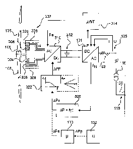
In Figure 3, a controlling of a synchronous generator 302 is schematically
represented. Of
the synchronous generator 302, the rotor 304 and the stator 306 are designed
in each
case as annular regions. Figure 3 shows this in an indicated sectional
representation, so
that they are shown as hatched regions. These hatched regions are essentially
the
magnetically effective regions of the rotor 304 and stator 306.
The rotor 304 is shown here as an inner-lying rotor, so that the synchronous
generator
302 is in this example designed as an internal rotor, and as a ring generator.
The rotor
304 is in this case fixedly connected to an indicated aerodynamic rotor 106.
This
aerodynamic rotor 106 consequently corresponds to the aerodynamic rotor 106
according
to Figure 1 and has correspondingly indicated rotor blades 108.
Merely for reasons of representation, only two rotor blades 108 are shown in
Figure 3.
For the sake of simplicity, the same reference signs as in Figure 1 have been
chosen
here to indicate that these may also be the same elements as in Figure 1. The
same
applies to the further elements of Figure 3, which have the same reference
signs as in
Figure 1 and/or Figure 2. Even though a different form of representation has
been chosen
in some cases, all of these elements coincide with the corresponding elements
of Figures
1 or 2 or both.
Date recue/date received 2021-10-22
CA 03137806 2021-10-22
- 21 -
The synchronous generator 302 may consequently be arranged in the nacelle 104
of the
wind turbine 100 according to Figure 1. The stator 306 of the synchronous
generator 302
is of a six-phase design, to be specific with two three-phase systems offset
by 30 degrees
in relation to one another. The stator 306 is fastened on a supporting frame
308, which is
only indicated. By means of this supporting frame 308, the synchronous
generator 302 is
consequently fastened in a nacelle like the one in the nacelle 104 of Figure
1, to be
specific on a machine carrier.
The six-phase stator current Is is then passed to an active rectifier 310. The
active
rectifier 310 rectifies this six-phase stator current Is and generates a
direct current with a
direct voltage and passes this to the DC link 312. The active rectifier 310
may in this case
also specifically control the stator current Is and thereby also control a
torque of the
synchronous generator 302. For this, the active rectifier 310 may receive a
setpoint power
value Ps and optionally a setpoint reactive power value as that is not shown
in Figure 3.
The setpoint power values Ps and possibly C), may for example be specified by
a control
unit 314. Such a setpoint power value Ps, which is thus specified by the
control unit 314,
may be specified for example dependently on a speed of the aerodynamic rotor
106 in a
way corresponding to a speed-power curve. The control unit 314 may
correspondingly
calculate this. Just for the sake of simplifying the representation, to this
extent an input of
a detected speed n into the control unit 314 is not shown. Otherwise, however,
the
schematically represented control unit 314 can in any case perform any
controls of the
wind turbine, or perform a large part of the control of the wind turbine, and
in this case
then have such a speed value available in any case.
Consequently, an operating point of the wind turbine is set by way of the
setpoint power
value Ps. In a special situation described further below, this power that has
been set may
be changed at least in the short term by a differential power LPF. To this
extent, APF is
shown in Figure 3 as a further input variable for the active rectifier 310.
In any event, the power or energy that the active rectifier 310 has input into
the DC link
312 is converted by the feed-in unit 101 into a three-phase alternating
current with a
three-phase alternating voltage and is finally fed into the electrical supply
grid 120 at the
common grid connection 118.
The schematically shown feed-in unit 101 can use the measured currents and
voltages,
particularly as they have been recorded by the current pickup 103 and the
voltage pickup
Date recue/date received 2021-10-22
CA 03137806 2021-10-22
- 22 -
105, in order to detect grid states of the electrical supply grid 120. One
possibility is to
detect a grid frequency fN as a grid state.
It may thus be provided that, dependent on the detected grid frequency, a
supporting
power is to be fed into the electrical supply grid, to be specific in addition
to the current
power, particularly in addition to the specified power Ps of the current
operating point. It
particularly comes into consideration here that, for short-term frequency
drops of the grid
frequency fN, a supporting power is to be fed into the electrical supply grid
quickly and
also only for a short time. A short time may particularly lie in the range
from 5 to 30
seconds. Such supporting power may lie in the range from 5 to 20 percent of
the current
output power of the synchronous generator 302, that is to say in the range
from 5 to 20
percent of the power Ps.
As a result, such additional supporting power can be generated by the
synchronous
generator that the latter is electrically braked, whereby kinetic energy is
converted into
electrical power. For this purpose, the active rectifier 310 may
correspondingly increase
the stator current Is. An exciter current may possibly be set. As a result,
the generator
torque also increases, which leads to said electrical braking of the rotor and
thereby an
increase in the power generated. Particularly, the aerodynamic rotor 106 but
also the
rotor 304, which may also be referred to as an electrodynamic rotor, is
thereby braked. Its
kinetic energy is therefore converted.
It has thus been recognized that, although such supporting power can be
helpful, it may
also constitute great loading of a mechanical nature for the wind turbine. It
is
correspondingly proposed to guide the changing of the electrical power, to be
specific the
increasing of the electrical power output by the generator, by the
differential power APt
such that a specifiable mechanical loading limit of the wind turbine is
maintained. One
possible way of implementing this is explained in Figure 3.
Accordingly, the feed-in unit 101 outputs the grid frequency fN and transfers
it to the
power changing block 320. The latter may have implemented a function which,
dependent on the frequency f that is input here as the grid frequency fN,
determines a
change in power. In simplified terms, it can be assumed that the power
changing block
320 also knows the rated grid frequency, that is to say the frequency that the
electrical
supply grid should have, that is to say usually 50 Hz or 60 Hz, to be specific
has
implemented or stored it. In this case, the implemented function will usually
take the form
Date recue/date received 2021-10-22
CA 03137806 2021-10-22
- 23 -
that, if the frequency corresponds to the rated frequency, the required change
in power
has the value 0.
In the example explained, it is however assumed that the grid frequency fN has
fallen
significantly below the rated frequency. Then, dependent on this, the power
changing
block 320 calculates a corresponding setpoint differential power value APs.
The output
power of the synchronous generator 302 is to be increased by this setpoint
power
changing value APs. This is based on the idea that power losses are negligible
and,
correspondingly, this increased power is also fed in, so that the electrical
feed-in power is
changed in the same way.
io In order then however to maintain specifiable mechanical loading limits
of the wind
turbine, this setpoint value of the power change APs is not given directly to
the active
rectifier 310 as a setpoint value, but is first passed via a filter element
322.
There are various possible ways in which this filter element 322 can be
configured. In
Figure 3, two of these possibilities are graphically indicated. Of them, the
left variant is
shown in a block depicted by solid lines and the right variant in a region
depicted by
dashed lines. It is intended to be indicated by this that these variants can
be alternatives.
The variant indicated in the left part of the filter element 322 is configured
as a lowpass
filter. Low frequencies are therefore allowed through and higher frequencies
are
attenuated all the more the higher they are. In the case of the setpoint value
of the
change in power APs, it comes into consideration that this setpoint value can
be
generated by the power changing block 320 with a very quickly changing grid
frequency
fN as a setpoint jump value or abruptly increasing setpoint value. In this
case, the rising
flank of such a jump value corresponds to a high-frequency signal or high-
frequency
component of a signal and the indicated lowpass filter would consequently
attenuate such
a steep flank correspondingly.
The variant shown on the right specifies a maximum gradient, to be specific
for the
amount of the change, so that a rising positive flank and falling negative
flank respectively
form the limits. The setpoint value entered in the filter block 322 is
consequently limited to
these flanks. Otherwise, there may of course be further variants than these
two variants
shown of the lowpass filter and of the limited gradients. A combination also
comes into
consideration.
Date recue/date received 2021-10-22
CA 03137806 2021-10-22
- 24 -
The result of the filter element 322 is a filtered change in power APF, which
is then input
into the active rectifier 310 as a setpoint value. Consequently, the active
rectifier 310
does not receive such a strong signal in the form of a jump through the filter
element 322,
so that the synchronous generator 302 can also correspondingly not be
controlled as
hard any longer.
However, it also comes into consideration here that the filter element 322 is
time-variant,
or is controlled in a time-variant manner, in order to change the respective
filter function.
This applies to the variant of the lowpass filter just as much as to the
variant of the limit
gradients, that is to say to other variants.
-io With such a time dependence or time-dependent control, it can
particularly be provided
and realized that how often the wind turbine, particularly the synchronous
generator 302,
has already had to withstand strong loading due to a sudden demand for a quick
increase
in power is taken into account. To be specific, it has been recognized that a
strong abrupt
increase in the power, which is accompanied by a correspondingly strongly
increasing
generator torque, does not directly damage the wind turbine, but in the case
of sustained
loading can be critical and can damage the wind turbine.
Sustained loading is in particular such loading in which such increases in
power are
demanded at short intervals, such as for example minute intervals, or 5 to 10
second
intervals. In this case, it then comes into consideration that the first such
increase in
power is still passed on unfiltered to the active rectifier 310, and
consequently as a result
to the synchronous generator 302. If, however, a further such demand for an
abrupt
increase in power comes in quick succession, then, or only after a
predetermined number
in a predetermined time period, the filter element 322 can have its effect in
such a way
that such a jump in power is no longer allowed through.
Here it has particularly been recognized that many such jumps in power in
quick
succession also pose the risk that the synchronous generator 302 or the rotor
106 is
made to oscillate. That can be avoided by the filter element 322, with in turn
a first abrupt
change in power being able to be passed on unfiltered.
A further variant is represented by dashed lines in Figure 3, accordingly to
be specific a
change in power is specified by a grid operator instead of by a measured grid
state. This
is indicated by the control center 132, which may correspond to the control
center 132 of
Figure 2. This control center may for example demand a change in power APp of
a farm
power. The grid control center may therefore demand that the farm power fed in
Date recue/date received 2021-10-22
CA 03137806 2021-10-22
- 25 -
altogether from a wind farm, such as the wind farm 112 of Figure 2, changes by
this
change in power of the farm power APP.
Such a demand for a changed farm power may be passed to a central farm control
130,
such as that shown in Figure 2. The central farm control 130 may then convert
this
setpoint value of a farm power into a setpoint value of a changed installation
power and
output it. The central farm control 130 therefore generates a setpoint value
of a change in
power LPs and inputs it into the filter element 322. This is a substitute for
specifying a
setpoint value for a change in power Alps, which according to the first
variant has been
generated by the power changing block 320. Otherwise, the further processing
of this
-io setpoint power value can be carried out in the filter element 322 as
explained above.
This proposes a solution which provides a changing of the feed-in power while
taking into
account mechanical loading. The changing of the feed-in power may arise from a
grid
state, including a grid oscillation, which can be detected. The grid state,
which may in
principle also comprise multiple elements and to this extent also stands
synonymously for
multiple grid states, can be detected particularly by the wind turbine or a
farm control, or
be input by way of an external interface, for example by a grid operator,
which in this way
can demand a change in power. These three possibilities may also be referred
to as 3
levels.
Particularly proposed is a solution for access to the rotational energy of the
rotor of the
wind turbine to improve the properties of the grid.
The solution consequently relates to the use of the rotational storage device
particularly
for local system services. This may include the provision of control power,
flywheel
replication, voltage impression or else a yield-optimized gradient
restriction.
It has been recognized that an active rectifier makes very high efficiency
gradients at the
generator possible, and consequently allows corresponding torque gradients to
be
realized. In this respect, to restrict mechanical loading, a corresponding
restriction is
proposed. Consequently, a reduction or limitation of the loadings of the
mechanical
structure with grid-related power gradients is proposed.
Preferably, a dynamic restriction of the efficiency gradients in dependence on
the loading
of the mechanical structure is provided.
Date recue/date received 2021-10-22
CA 03137806 2021-10-22
- 26 -
It has particularly been recognized that access to the rotational energy of
the rotor may
take place through an active rectifier, whereby high torque gradients at the
rotor shaft
become possible. As a result, high loadings of the mechanical structure are
possible.
New system services allow the mechanical oscillation system of a wind turbine
to become
coupled with the oscillation systems in the grid. This is counteracted by the
proposed
solution.
Particularly the following is proposed:
Restricting the torque gradients or the variation in torque to avoid
mechanical stress or
exceeding of maximum loads.
to Particularly, a gradient restriction is proposed, and/or a displacement
of an excitation
spectrum by making the variation in torque more uniform, for example by a
lowpass filter,
particularly according to a delay element of the first or second order
(PT1/PT2).
One proposal is to specify definitions of the dead times that are to be
maintained after
sudden torque changes. One variant is to wait for the decay of a mechanical
oscillation.
A further fundamental approach is the avoidance of mechanical oscillations. In
this
respect, it may be proposed to take into account the resonant frequencies in
the
mechanical system in the control of the generator torque.
The placing of the poles in the control that is used also comes into
consideration,
accordingly a distance of the poles in the complex plane from the imaginary
axis is set or
increased.
Most preferably, a mapping of the mechanical model in the control takes place.
One variant proposes a detection of the vibrations and reaction of the
generator control,
in order thus for the control system to respond to such oscillations.
An avoidance of any excitations by way of specifying a specific frequency
range as a limit
curve is also proposed. This may also depend on a predetermined amplitude, or
the
amplitude is specified as the limit curve.
Date recue/date received 2021-10-22
CA 03137806 2021-10-22
- 27 -
Particularly arising as advantages of the proposed solutions are an
avoidance/a reduction
of mechanical stress at the same time as an improvement of the properties of
the grid in
comparison with solutions that do not take mechanical loadings into account.
A decoupling of the oscillation systems of the electrical supply grid on the
one hand and
the wind turbine on the other hand is also possible. This can be achieved by
adapted
generator control that takes these two oscillation systems into account.
It has particularly been recognized that, when there is a change in the
generator torque,
the mechanical structure may be particularly loaded in the following two ways.
In the case of the first type of loading, an absolute one-off loading occurs
directly when
there is the jump in torque. This can have effects on bending of the tower of
the wind
turbine, on bending of the rotor blades and on maximum loads and lifetime
loads.
A second type of loading is produced by a cyclical torque variation. This can
give rise to
an excitation of a resonance in the mechanical system.
In this respect, resonant frequencies of the mechanical system should be
noted. A first
tower oscillation may lie in the range of 0.25 Hz. A second tower oscillation
may lie in the
range of 1-3 Hz.
A first blade frequency in the flapwise direction may lie in the range of 0.55
Hz, and a first
blade frequency in the chordwise direction may lie in the range of 0.75-0.9
Hz.
For this purpose it is proposed to take into account frequencies in the
electrical supply
grid. In this respect it has been recognized that so-called inter-area
oscillations, that is to
say oscillations in power between portions of the grid, may lie in the range
of 0.2-0.8 Hz.
So-called power system oscillations (PSO), that is to say local oscillations
in power, may
have frequencies from 1 Hz. Furthermore, so-called subsynchronous resonances
(SSR),
that is to say voltage oscillations with frequencies below the grid frequency,
may
particularly lie in the range of 15 Hz.
Date recue/date received 2021-10-22