Note : Les descriptions sont présentées dans la langue officielle dans laquelle elles ont été soumises.
WO 2020/254233
PCT/EP2020/066459
SYSTEM AND METHOD FOR PREPARING
A CATHETER BEFORE USE
FIELD OF THE INVENTION
100011 This invention relates to a method of
preparing a catheter for use in a
patient, in particular purging and de-airing, and further relates to a
respective system
including the catheter. The catheter may be part of an intravascular blood
pump for
percutaneous insertion into a patient's blood vessel.
BACKGROUND OF THE INVENTION
100021 Before using a catheter in a patient, more specifically
before inserting the
catheter into a patient's blood vessel, the catheter must be properly
prepared. In
particular, the catheter must be purged and de-aired to prevent air or other
gas bubbles
from being introduced into the patient, which could cause severe
complications, such as
an infarct. Typically, a catheter comprises an elongate tubular body having a
proximal
end and a distal end, with the distal end being the leading end upon insertion
into the
patient. The tubular body has a lumen which extends through the catheter from
the
proximal end to the distal end for receiving functional structures, lines or
the like,
depending on the application or for supplying fluids, e.g. including
pharmaceuticals, to
the patient. The lumen includes air before use and shall be completely de-
aired before
the catheter is inserted into the patient. For de-airing and purging, a fluid
may be
pumped through the catheter with a certain pressure.
100031 De-airing the lumen of the elongate tubular
body of the catheter usually
is not a problem because of its smooth geometry and small diameter. The lumen
typically does not have any convexities, and the small diameter causes
capillary forces
that draw the purge fluid through the lumen to eliminate any air bubbles or
other gas
bubbles. However, the catheter may be in fluid communication to at least one
connected
device, e.g. a pump unit or a handle portion, which can be held by a user to
maneuver or
otherwise control the function of the catheter. Depending on the application,
a
connected device may have at least one cavity which is in fluid communication
with the
- 1 -
CA 03140107 2021-11-30
WO 2020/254233
PCT/EP2020/066459
lumen of the catheter and which has a fluid inlet for receiving the purge
fluid. The
cavity of a connected device may have a complex geometry and may accommodate
functional and possibly movable parts, such that air bubbles may still be
trapped in the
cavity although the purge fluid already exits the catheter at the distal end.
In particular,
5
if a user does not correctly hold the
connected device, for instance not in a correct de-
airing orientation which may be on an upright and vertical orientation, air
bubbles may
be trapped inside the cavity. According to the state of the art, it highly
depends on the
experience of the user, who may be for instance a surgeon, cardiologist,
general
practitioner, or other medical staff, to determine when the catheter and
connected
10 devices are completely de-aired.
[0004]
The aforementioned problem of
de-airing the catheter, in particular a
connected device, may be particularly relevant to intravascular blood pumps.
An
intravascular blood pump is configured for percutaneous insertion into a
patient's blood
vessel and comprises a pump unit with a rotatable impeller for conveying blood
from a
15
blood flow inlet to a blood flow outlet of the
pump unit. A drive unit is provided to
cause rotation of the impeller.
100051
In one type of intravascular
blood pumps the pump unit comprises a
drive unit which is directly coupled to the impeller and is included in a
common pump
casing together with the pump unit. The common pump casing may be arranged at
the
20
distal end of the catheter. De-airing of the
catheter may be required before insertion into
a patient.
100061
In another type of
intravascular blood pumps, the drive unit may be
coupled to the impeller by means of a flexible drive shaft which extends
through the
lumen of the elongate tubular portion of the catheter, wherein the drive unit
may be
25
disposed in a cavity of a handle portion. In
this type of intravascular blood pump, the
pump unit with the impeller may be expandable. The drive unit may comprise an
electric motor including a stator and a rotor and further electronic parts to
control
rotation of the drive unit, which may create convexities, undercuts or other
cavities in
which air bubbles might be trapped. Since the drive unit, such as the moving
parts of an
30
electric motor, may be immersed in the purge
fluid, it is even more difficult to properly
- 2 -
CA 03140107 2021-11-30
WO 2020/254233
PCT/EP2020/066459
eliminate all air bubbles from the cavity in the handle portion. Thus, it is
important that
a user holds the catheter, in particular the handle portion, in a de-airing
orientation
during purging and de-airing to avoid causing harm to the patient.
SUMMARY OF THE INVENTION
100071 It is therefore an object of the present
invention to provide a method of
preparing, in particular purging, a catheter for use in a patient and a
respective system
including the catheter, which allows securely de-airing the catheter,
particularly before
insertion into a patient. In particular, the catheter may be part of an
intravascular blood
pump.
100081 This object is achieved according to the
present invention by a system
and a method having the features of the independent claims. Preferred
embodiments and
further developments of the invention are specified in the claims dependent
thereon.
100091 According to a first aspect of the
invention, a system is provided which
comprises a catheter as described above, in particular comprising an elongated
tubular
portion and a connected device which is connected to the catheter. The
elongate tubular
portion has a lumen. The connected device has at least one cavity. As
explained above,
before the catheter is used in a patient, the lumen and the cavity should be
de-aired, i.e.
air bubbles should be completely removed. In order to monitor the orientation
of at least
one connected device and for the elongate tubular portion, preferably a
connected
device as is described in more detail below, the system further comprises at
least one
sensor for detecting said orientation.
[00101 According to a second aspect of the
invention, a method of preparing a
catheter for use in the patient is provided. In particular, the catheter is
constructed as
explained above having an elongated tubular portion and a connected device. In
the
method of preparing the catheter, in particular purging the catheter, a fluid
is supplied
through a fluid inlet into the at least one cavity of the connected device and
thereby into
the lumen of the elongate tubular portion to purge said cavity and lumen. The
method
- 3 s.
CA 03140107 2021- 11- 30
WO 2020/254233
PCT/EP2020/066459
further comprises the step of detecting the orientation of at least one
connected device
and of the elongate tubular portion, preferably during the fluid supply.
[0011]
In the system and method of the
present invention, an orientation of at
least one connected device and/or the elongate tubular portion, preferably a
connected
device, can be detected. Thus, the system and the method of the present
invention do
not rely on the experience of the user to correctly orient the catheter,
especially of a
connected device, but provide means to monitor the orientation of at least a
portion of
the catheter, in particular during the purging process. It will be appreciated
that the term
"connected device" may refer to any structure connected to the elongate
tubular body
which can be manipulated by a user, in particular holding it by a user in his
hands or
turning it together with the patient, and which has a cavity in fluid
communication with
the lumen of the elongate tubular body.
[0012]
The term "orientation"
particularly refers to the orientation of the
respective portion of the catheter in three-dimensional space relative to a
fixed reference
system such as gravity. In particular, the orientation does not necessarily
include an
absolute position of the respective portion of the catheter in three-
dimensional space,
but may rather be regarded as a "relative position", for instance relative to
a vertical or
horizontal axis or plane in three-dimensional space or any other suitable
reference point
or system. For instance, the orientation may refer to a tilt of the respective
portion of the
catheter and may be indicated as an angle in degrees, e.g. relative to a
vertical axis or
horizontal plane. A vertical axis can be oriented in direction of gravity.
[0013]
A control unit may be provided,
which may receive data from the at least
one sensor, the data particularly including the detected orientation, i.e.
data representing
the actual or current orientation of the respective portion of the catheter.
The data may
be transmitted by wire or wirelessly. It may be determined whether the
detected
orientation matches an orientation in which a cavity can be de-aired. This may
be the
cavity of which the orientation is detected. A difference between the detected
orientation and a predetermined orientation, i.e. a predefined orientation
which should
be achieved by a user orienting the catheter, may be calculated. The
predetermined
- 4 -
CA 03140107 2021-11-30
WO 2020/254233
PCT/EP2020/066459
target orientation is not necessarily a unique orientation but may include a
range of
orientations suitable for proper purging as will be explained in more detail
below.
100141 Based on said difference between the
detected orientation and the
predetermined orientation, a user may be guided to change, i.e. to correct,
the
orientation of the respective portion of the catheter to approach the
predetermined
orientation. The respective portion of the catheter can be moved such that it
matches the
predetermined orientation or at least lies within a -range defined by the
predetermined
orientation. It will be appreciated that a tolerance may be allowed. For
instance, a user
interface, such as a display or the like, may be provided in the control unit,
which may
display the detected orientation or a representation indicating the difference
between the
detected orientation and the predetermined orientation or both. Alternatively
or
additionally, it may display the matching of the detected orientation with an
orientation
in which a cavity may be de-aired, which may be a predetermined orientation.
For
instance, an image of the respective portion of the catheter indicating its
orientation in
real time may be displayed, or a simple graphic, such as a line or the like,
may be
displayed indicating the tilt angle. Additionally or alternatively, the
difference between
the detected orientation and the predetermined target orientation can be
displayed. For
instance, any suitable graphic, such as a symbol, color scale (e.g. red-yellow-
green) or
the like may be displayed. Alternatively or additionally, the difference may
also be
indicated by means of any suitable acoustic signal, which enables the user to
change the
orientation to approach the predetermined target orientation.
100151 Guiding the user to correct the orientation
of the respective portion of the
catheter can improve the purging process and can reduce or eliminate the risk
of air
bubbles being trapped inside the cavity or lumen. In particular, a complex
geometry
inside the cavity or lumen, e.g. comprising convexities, undercuts or the
like, may
require the user to hold the respective portion of the catheter in the
predetermined
orientation such that air bubbles can exit.
[0016] Since air bubbles move in the purge fluid
in a vertically upward
direction, the predetermined orientation is preferably a vertical or
substantially vertical
orientation or a conical range defined by a vertical axis and a predetermined
angle. It
- 5 -
CA 03140107 2021- 11- 30
WO 2020/254233
PCT/EP2020/066459
will be appreciated that any other orientation may be possible, depending on
the
geometry of the cavity or lumen to be de-aired. For instance, depending on the
interior
geometry, an angle of 45 degrees or any other angle could be necessary or
suitable to
completely de-air the cavity. As mentioned above, the "predetermined
orientation" may
include a range of orientations, e.g. range of angles, within which it is
possible to
completely de-air the cavity and lumen of the catheter. For instance, if the
cavity has a
smooth and regular geometry, it may be sufficient if the user holds the
respective
portion of the catheter, in particular the connected device, within a range of
45 or 30
degrees in any direction with respect to a vertical axis. Preferably, the
orientation can be
detected in the range of 0 to 180 degrees, e.g. to determine which end of the
handle
portion faces upward and which end faces downward. Generally, in order to
ensure
proper de-airing, the fluid inlet of the handle portion should be located
below an exit to
the lumen of the elongate tubular portion, with respect to a vertical
direction. For
example, an orientation angle can refer to a longitudinal main direction of
the catheter
or a connected device.
[0017] It will be appreciated that the
predetermined orientation, regardless of
whether it refers to a single orientation or a range of orientations, may not
only refer to
the tilt., i.e. angle relative to an external reference system, of the
respective portion of
the catheter, but may also refer to any other degree of freedom, such as
rotation about a
longitudinal axis of the respective portion of the catheter. For instance, in
particular if
the predetermined orientation is other than a vertical orientation, it might
be necessary
to rotate e.g. the connected device about its longitudinal axis to a
predetermined
orientation to remove all air bubbles from the cavity.
100181 In one embodiment, a user may start the
purge process and a fluid, i.e.
any suitable purge fluid, will be supplied to the cavity of the connected
device and
thereby into the lumen of the tubular portion of the catheter. The purge fluid
may be
continuously supplied to the cavity and lumen of the catheter while the user
is
continuously guided to hold the respective portion of the catheter in the
correct
orientation, i.e. to change the orientation if necessary.
- 6 -
CA 03140107 2021-11-30
WO 2020/254233
PCT/EP2020/066459
[0019] In a preferred embodiment, however, the
fluid supply may be activated,
in particularly activated only, if the detected orientation matches the
predetermined
target orientation, i.e. if the user correctly orients the catheter and/or a
connected device
the respective portion of the catheter. Similarly, the fluid supply may be
deactivated, i.e.
stopped or paused, if the detected orientation differs from the predetermined
target
orientation, i.e. when the user does not correctly orient the respective
portion of the
catheter. Particularly in this embodiment, it may be advantageous to measure
the
volume of the supplied fluid. Thus, if the measured volume of the supplied
fluid reaches
a known volume of the cavity and the lumen to be purged, and due to the fact
that air
bubbles are able to exit the cavity and lumen at all times because of the
correct
orientation, a conclusion can be drawn that de-airing is complete. The system
may then
notify the user that purging is complete. It will be appreciated that a
certain safety
margin, i.e. additional purge fluid volume can be added until the system
indicates a
successful completion of the purging process. In addition, the user may be
requested to
confirm that the purge fluid exits the catheter at the distal end to complete
the purging
process.
[0020] As explained above, there may be no
problems of purging the lumen of
the elongate tubular portion of the catheter, while purging the at least one
cavity of a
connected device may be difficult.
In another preferred embodiment, the at least one sensor is arranged in the
connected
device of the catheter in order to detect its orientation. It may not be
necessary to detect
the orientation of the elongate tubular portion of the catheter.
100211 The at least one sensor to detect the
orientation of the respective portion
of the catheter, in particular the orientation of at least one connected
device, may be at
least one of a gravity sensor, an accelerometer and a gyroscope. For the sake
of
convenience, any of these terms may refer to all of these terms. However, the
term
"sensor" in the sense of the present disclosure may include any other type of
active or
passive sensor, means or system which is able to detect an orientation of the
respective
portion of the catheter in three-dimensional space. These may include sensors
which are
based on a magnetic or electromagnetic field, optical sensors or the like.
- 7 -
CA 03140107 2021- 11- 30
WO 2020/254233
PCT/EP2020/066459
For instance in another embodiment, the at least one sensor may be arranged at
a
distance to the catheter. The sensor may be formed by a camera system which
records
the respective portion of the catheter, in particular the orientation of at
least one
connected device, and detects the orientation from the recorded image.
5 [0022]
However, a sensor is preferred which is easy
to implement in existing
systems and which provides reliable results. For instance, the advantage of a
gravity
sensor or accelerometer is that it does not require any external
infrastructure, like
external sensors or external field generators. In addition, an accelerometer
is robust
against external perturbations, such as a magnetic field, which may be caused
for
10
instance by an electric motoric of an
intravascular blood pump. An accelerometer may
be designed as a MEMS device or nanodevice and can be arranged on a printed
circuit
board (PCB) or printed circuit assembly (PCA) which already exists for example
in a
drive unit of an intravascular blood pump.
[0023]
A gravity sensor or
accelerometer may detect a "downward" direction,
15 more specifically in a vertical direction. This "downward" direction, which
represents
the detected orientation, may be transferred to the control unit using memory-
mapped
register technique. That means, the sensor data, i.e. the detected orientation
(downward
direction) is stored in a memory, e.g. a memory of the blood pump. Every time
the
control unit reads a specific byte of the pump memory, the control unit gets
the detected
20 orientation, e.g. the tilt in degrees, instead of the memory content. That
means, the
accelerometer does not need an additional connection, e.g. wires, to the
control unit to
transfer the data of the sensor but uses the existing communication connection
that reads
the memory.
100241
As mentioned above, the system
and method according to the present
25 invention may be particularly advantageous when used in connection with an
intravascular blood pump, in particular an intravascular blood pump with a
pump unit
connected to an elongate body of the catheter. In this type of intravascular
blood pumps,
the interior of the catheter is in fluid communication with the environment
and is purged
during operation of the pump and has to be completely de-aired before use in
order to
30 avoid introducing air bubbles into the patient's vascularity. By detecting
the orientation
- 8 -
CA 03140107 2021-11-30
WO 2020/254233
PCT/EP2020/066459
of the at least one connected device and guiding a user to correctly orient
the catheter,
especially at least one of the connected devices, the respective cavities can
be securely
de-aired. The pump unit may be expandable, i.e. it may be compressed into a
compressed configuration for insertion into the blood vessel, and may be
released and
expanded once placed at the target position as will be appreciated by a person
skilled in
the art.
BRIEF DESCRIPTION OF THE DRAWINGS
[0025] The foregoing summary, as well as the
following detailed description of
preferred embodiments, will be better understood if read in conjunction with
the
appended drawings. For the purpose of illustrating the present disclosure,
reference is
made to the drawings, which are to be understood as schematic and may not be
true to
scale. The drawings are exemplary for illustrating the present invention, and
the scope
of the disclosure is not limited to the specific embodiments disclosed in the
drawings. In
the drawings:
FIG. 1 shows a system in accordance with an embodiment of the present
invention,
including an intravascular blood pump connected to a control unit.
FIG. 2 shows the blood pump of FIG. 1 in more detail.
FIG. 3a to FIG. 3c schematically illustrate a handle portion or a pump unit of
a catheter
at different orientations during the purging process.
DETAILED DESCRIPTION
[0026] FIG. 1 shows a system 100 in accordance
with an embodiment of the
present invention. In particular, the system 100 comprises an intravascular
blood pump
10 connected to a control unit 5. The intravascular blood pump 10 comprises a
catheter
1 with a pump unit 2 connected to the distal end 22 of the catheter 1, more
specifically
to an elongate tubular portion 11 of the catheter I (see FIG. 2). The pump
unit 2 is also
- 9 -
CA 03140107 2021-11-30
WO 2020/254233
PCT/EP2020/066459
called a connected device 230_ A handle portion 3 is connected to a proximal
end 21 of
the elongate tubular portion 11. The handle portion 11 is also called a
connected device
230. The handle portion 3 can be grabbed by a user for handling the catheter 1
and will
not be inserted into the patient. The intravascular blood pump 10 may be
designed to act
5 as a left ventricular assist device and may be inserted into a patient's
aorta toward the
heart, more specifically the left ventricle of the patient's heart. In this
case, the pump
unit 2 will be placed through the aortic valve to convey blood from the left
ventricle
into the aorta. However, it will be appreciated that the blood pump 10 may be
designed
for a different application, such as to act as a right ventricular assist
device, or the
10 catheter may be designed for a different field than intravascular blood
pumps.
[0027] Still referring to FIG. 1, the handle
portion 3 accommodates a drive unit
4 of the blood pump 10, which will be explained in more detail below. In order
to
control the drive unit 4, an electric connecting cable 7 is provided
connecting the
intravascular blood pump 10 to the control unit 5. The control unit 5 has a
user interface
15 comprising a display 6. It will be appreciated that the control unit 5 may
comprise
various further control elements, such as a touch screen, control dials,
buttons or the
like. The display 6 may be configured to display various operation parameters
of the
blood pump 10, such as pump flow rate, pump speed, motor current, etc. In
particular,
in view of the present invention, the display 6 may display during an initial
purging
20 process a representation of the orientation of a connected device 230,
for example the
handle portion 3, which is detected by a sensor 15. As indicated in FIG. 1,
the current
orientation 27 of the connected device 230 may be displayed relative to a
predetermined
target orientation 28 of the connected device (indicated in dashed lines in
FIG. 1). Any
other display options suitable to guide a user may be implemented. Further, or
in an
25 alternative example, the orientation 27 of the pump unit 2 may be
displayed.
[0028] Besides the electrical connection, the
blood pump 10 is further connected
to a purge line 8 which is provided for supplying a purge fluid to the blood
pump 10 for
an initial purging and de-airing process as well as during operation of the
blood pump
10. The purge line 8 may be connected to a purge cassette 9, which may be
provided for
30 generating a certain purge pressure, which may be for instance 500 mmHg. A
purge
fluid, which may be any suitable fluid, such as water, or preferably a
dextrose solution,
- 10 -
CA 03140107 2021-11-30
WO 2020/254233
PCT/EP2020/066459
may be provided in a container or bag 17 and supplied to the purge cassette 9
and
further, via the purge line 8, to the blood pump 10. Details of the method of
preparing
the blood pump 10 will be described in more detail below with respect to FIG.
3a to
FIG. 3c.
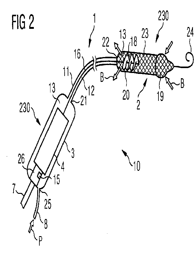
[0029] Referring now to FIG. 2, the intravascular blood pump 10 of
the system
100 of FIG. 1 is described in more detail. The blood pump 10 comprises two
connected
devices 230 which are the handle portion 3 and the pump unit 2. Each of the
connected
devices 230 comprises a cavity 13. Each of these cavities 13 is in fluid
communication
with a lumen 12 of the elongate tubular body 11. The blood pump 10 of the
embodiment
shown is an expandable catheter pump, in other words, the pump unit 2 is
expandable
from a compressed configuration (not shown) to an expanded configuration. More
specifically, in order to insert the blood pump 10 through a small access into
a patient's
blood vessel, the pump unit 2 will be compressed to the compressed
configuration to
reduce its diameter. Once placed at a target location, for instance the left
ventricle and
the aorta, the pump unit 2 may expand. For this purpose, the pump unit 2 may
comprise
an expandable pump casing 23, which may be in the form of a cannula and may be
formed of a mesh-like support structure covered by a thin polymer membrane.
The
support structure may be made of a shape memory material, such as nitinol. The
pump
unit 2 may have at its distal end an atraumatic tip 24, also known as J-tip or
pig tail. An
impeller 18, which may be expandable and compressible, respectively, as well,
is
disposed inside the pump casing 23. In particular in the aforementioned
application for
left ventricular support, a blood flow inlet 19 may be formed in a distal
portion of the
pump casing 23, for instance in an enlarged diameter portion. Blood enters the
pump
casing 23 and is conveyed by means of an impeller 18 rotating about an axis of
rotation
through the pump casing 23, and out of a blood flow outlet 20 (indicated by
arrows B).
[01130] The impeller 18 is coupled to a flexible
drive shaft 16, which extends
through the catheter 1, more specifically through the lumen 12 of the elongate
tubular
body 11 of the catheter 1. The flexible drive shaft 16 is coupled to a drive
unit 4 which
is located inside the cavity 13 of the handle portion 3. The drive unit 4,
which is only
schematically illustrated in FIG. 2, may comprise an electric motor. Further
electronic
- 11 -
CA 03140107 2021-11-30
WO 2020/254233
PCT/EP2020/066459
parts of the drive unit 4, such as a PCB 26, are connected to the cable 7,
which in turn is
connected to the control unit 5 as explained above with respect to FIG. 1.
100311 A sensor 15 for detecting the orientation
of the handle portion 3 is placed
on the PCB 26 to be able to transmit data relating to the current orientation
to the
5 control unit 4. Before use in the patient, in particular the cavity 13 of
the handle portion
3 and the lumen 12 of the elongated tubular portion 11 of the catheter 1, and
also the
pump unit 2, have to be completely de-aired, that means air bubbles have to be
completely removed from all cavities of the blood pump 10 to prevent air from
being
introduced into the patient's vascularity, which may cause severe
complications, such as
an infarct. In order to supply a purge fluid to the blood pump 10, the purge
line 8 is
connected to a purge fluid inlet 25 of the handle portion 3. A person skilled
in the art
will understand that various connectors, such as Y-connectors, Luer-connectors
or the
like may be used to connect the various lines and cables. Further or in the
alternative, a
sensor may be placed in the pump unit, additionally or alone.
15 [00321 Referring now to FIG. 3a to FIG. 3c, a method of
preparing a catheter in
accordance with an embodiment of the present invention is described. In
particular, as
explained above, during the preparation of catheter I before it can be used in
a patient,
air bubbles shall be completely removed. While there is substantially no risk
that air
bubbles are trapped in the lumen 12 of the elongate tubular body 11 of the
catheter 1, air
bubbles might be trapped inside the cavity 13 of connected devices as the
handle
portion 3 and/or the pump unit 2. In particular, there is a risk that purge
fluid exiting the
catheter 1 at the distal end 22 (i.e. exiting the pump unit 2) may erroneously
imply that
the catheter 1 has been successfully de-aired. This is because the cavity 13
of the handle
portion 3 (or the pump unit ¨ not shown) may have recesses or other
geometrical
25 structures of the inner wall or of built-in components which may still
be filled with air
while the purge fluid already flows through the lumen 12 of the elongate
tubular portion
11 of the catheter 1. In particular, the lumen 12 may have a very small
diameter such
that capillary forces may draw the purge fluid into the lumen 12 although
there still is
air in the cavity 13 of the handle portion 3 and/or the pump unit.
Furthermore, the
cavities or built-in components may have irregular structures that further
increase the
risk of entrapped air bubbles.
- 12 -
CA 03140107 2021-11-30
WO 2020/254233
PCT/EP2020/066459
100331 The risk of air bubbles being trapped
inside the handle portion 3 and/or
the pump unit 2 can be substantially reduced or eliminated if the handle
portion 3 and/or
the pump unit 2 is held in a correct orientation during the initial purge
process for de-
airing the catheter 1. Therefore, the system 100 of the present invention
includes a
sensor 15 for detecting the orientation of the handle portion 3 and/or the
pump unit 2. In
other words, the current orientation of the handle portion 3 and/or the pump
unit 2 can
be detected while supplying the purge fluid through the line 8 (see arrow P)
into the
handle portion 3 or into the pump unit via the tubular portion 11. In
particular, the
current orientation may be detected continuously or at certain time intervals,
preferably
very short time intervals, such that the orientation can be properly
monitored.
10034] The sensor 15 may be a gravity sensor,
accelerometer, gyroscope or any
other sensor, which is able to detect an orientation. In particular, it is
sufficient to detect
the orientation, and it may not be necessary to detect the absolute position
of the handle
portion 3 and/or the pump unit 2 in three-dimensional space, particularly in
relation to
gravity. Especially an accelerometer does not require any external
infrastructure, like
external field generators or the like, and is robust against a magnetic field,
which may
be caused by the drive unit 4. Thus, an accelerometer may provide an exact
orientation.
[00351 In particular, the orientation may be
represented by a tilt angle a
enclosed by a general longitudinal axis L and/or the pump unit 2 and a
vertical axis V.
preferably along gravity. As indicated by the arrows in FIG. 3a to FIG. 3c, an
accelerometer 15 typically detects a vertically downward direction. The sensor
data can
then be used to calculate the tilt angle a relative to the particular downward
direction.
The detected orientation may be transmitted to the control unit 5. Preferably,
the sensor
data obtained by the sensor 15 are transmitted using memory mapping, which
eliminates
the need for further connection wires, and the existing connecting cable 7 can
also be
used for transmitting the sensor data. The control unit 5 can display the
detected
orientation calculated from the sensor data on a display 6 as illustrated in
FIG. 1.
Further, the control unit 5 may be configured to guide the user to change the
orientation
of the handle portion 3 or the pump unit 2 toward a predetermined target
orientation. As
illustrated in FIG. 3a to FIG. 3; the display 6 may also give a positive and
negative
- 13 -
CA 03140107 2021- 11- 30
WO 2020/254233
PCT/EP2020/066459
indication 29 whether the current orientation matches the predetermined target
orientation or not, respectively.
100361 A de-airing process will be described with
the handle in FIG. 3a-3c as an
example that can also be applied to the pump unit 2 analogously: The
predetermined
target orientation may be chosen depending on the interior geometry of the
handle
portion 3, to be the orientation in which air bubbles can securely exit the
cavity 13 of
the handle portion 3 into the lumen 12 of the elongated tubular portion 11 of
the
catheter 1. The predetermined target orientation may be a vertical orientation
as shown
in FIG. 3a, in which further a purge fluid line 8 is located vertically below
the proximal
end 21 of the tubular portion 11, i.e. at an angle a of 0 degrees, or, in
other words, in
which the vertical axis V is coincident with the longitudinal axis L. In this
orientation,
the purge fluid 30 is introduced from below and can securely push any air 31
in a
vertically upward direction such that the cavity 13 and that the lumen 12 can
be securely
de-aired. It will be appreciated that any angle a greater than 0 or any range
of angles
may be selected to define the predetermined target orientation.
[0037] As shown in FIG. 3b, if the handle portion
3 is held at an oblique angle,
for instance an angle a greater than 0 degree and below 90 degrees, such as 45
degrees,
air 31 may be trapped in a corner of the cavity 13 of the handle portion 3
while the
purge fluid 30 already is present in lumen 12. Likewise, as shown in FIG. 3c,
if the
handle portion 3 is held in an orientation in which the fluid inlet into the
handle portion
3 is located vertically above the exit into the lumen 12, i.e. for instance at
an angle a
greater than 90 degrees up to 180 degrees, air 31 may be trapped in a corner
of the
cavity 13 of the handle portion 3. Nevertheless, purge fluid may continuously
exit the
catheter 1 at the distal end 22, thereby making the user erroneously believe
that he has
successfully de-aired the catheter 1.
[00381 Therefore, the user is guided how to hold
the handle portion 3, in other
words how to change the orientation of the handle portion 3 such that it
matches the
predetermined target orientation. The detected orientation, that means the
current
orientation detected by the sensor 15 is compared to the predetermined target
orientation
and a suitable indication is displayed on the display 6, e.g. at least one of
the indications
- 14 -
CA 03140107 2021-11-30
WO 2020/254233
PCT/EP2020/066459
27, 28 and 29 as described above. It will be appreciated that any indication
representing
the difference between the current detected orientation and the predetermined
target
orientation suitable to guide a user to choose the correct orientation may be
envisioned,
such as graphic illustrations, color scales, arrows or the like. Likewise, in
addition or
alternatively, an acoustic signal may be used to guide the user to change the
correct
orientation to approach and match the predetermined target orientation, which
is
necessary for completely de-airing the system.
100391 While the purge fluid may be continuously
supplied by the fluid line 8 to
the cavity 13 and to the lumen 12 during the aforementioned purging and de-
airing
process, it may be advantageous to activate the flow of purge fluid only if
the user holds
the handle portion 3 in the correct orientation. Vice versa, the flow of purge
fluid may
be stopped or paused if the user does not correctly hold the handle portion 3.
This may
reduce or eliminate the risk that the purge fluid is drawn into the lumen 12
too early
although air is still present in the handle portion 3. The volume of supplied
purge fluid
may be measured such that based on the known volume of all cavities in the
catheter I,
an indication may be displayed once the purging and de-airing process is
completed.
For safety reasons, the control unit 5 may prompt the user to confirm that the
purge
fluid exits the blood pump 10 at the distal end, and a safety margin for the
amount of
purge fluid may be added.
109401 The disclosed method and system allow for
proper and secure
preparation of a catheter for use in a patient, in particular proper purging
and de-airing
the catheter in order to prevent air bubbles from being introduced into the
patient's
vascularity. It will be appreciated that the invention is particularly useful
in the field of
intravascular blood pumps but may be implemented in any catheter which
requires
proper de-airing before used in a patient.
- 15 -
CA 03140107 2021-11-30