Note : Les descriptions sont présentées dans la langue officielle dans laquelle elles ont été soumises.
MONITORING SYSTEM
BACKGROUND
Technical Field.
[0001] The subject matter described relates to systems and methods that
monitor vehicles
of a vehicle system.
Discussion of Art.
[0002] A positive vehicle control (PVC) system is a monitoring system
that monitors the
locations of numerous vehicles in a network of routes and communicates with
the vehicles to
prevent collisions or other unsafe traveling conditions. PVC systems may
operate by determining
which segments of routes are occupied by vehicles, are undergoing maintenance,
or the like, and
generating signals that inform the respective vehicles as to whether the
vehicles can enter into
certain route segments. Without receiving such a signal, the PVC system may
prevent the
respective vehicle from entering a route segment. One example of a PVC system
is a positive train
control (PTC) system.
[0003] A PVC system may need accurate speed readings related to vehicles
within the
vehicle system. Specifically, PVC systems may determine an accurate speed to
safely predict when
to enforce a target. The calculated braking curves are very dependent on speed
and even a small
error in speed (e.g., one to two miles per hour) can have a significant effect
on calculated braking
distance. PVC systems may use multiple sensors that are compared and filtered
to determine an
accurate speed. In a rail vehicle setting, the primary speed source is a wheel
tachometer. Still,
because the tachometer is directly coupled to the wheel of a locomotive, the
tachometer is prone
to detect speed changes when the wheel slips or slides along the rail.
Therefore, PVC systems may
use alternate speed sources such as GPS to filter and validate speed so that a
wheel slip or slide
event can be detected and handled by some means that is safe and maintains
accuracy.
[0004] However, for some vehicles, navigation satellite systems can be
insufficient to
determine the speed of the vehicle. For example, vehicles often travel through
tunnels, in and out
of buildings, in remote locations, in urban locations having tall buildings,
in mountainous regions,
1
Date recue / Date received 2021-11-29
etc., all of which can result in spotty navigation system coverage and
difficulties in determining
vehicle location. As a result, when a speed change is detected as a result of
wheel slip and the
navigation satellite system is unable to accurately determine the speed of the
vehicle, the PVC
system often cannot identify the wheel slip, resulting in inaccurate
determination by the PVC
system.
[0005] The current wheel slip/slide detection design monitors the wheel
tachometer speed
for a large acceleration or deceleration within a short time period (e.g., one
second) as a potential
slip or slide event. Speed is then compared against a speed determined by the
navigation satellite
system. Because of inaccuracies of the speed determined by the wheel
tachometer, the speed
determined by the PVC system is determined to be the last or previously
determined tachometer
speed (determined before the slip or slide event). The last determined
tachometer speed is then
used for calculating braking curves to restrict movement for up to ten seconds
until the wheel
tachometer speed again matches the speed determined by the navigation
satellite system. In this
manner, the braking curve calculations are made utilizing the last determined
speed until the match
occurs to account for slip or slide events. In most actual slip or slide
events, the locomotive
monitoring system corrects the loss of adhesion causing the slip or slide
event, and the wheel
tachometer and satellite navigation system speed sources converge again, and
the true speed of the
locomotive is once again known. Still, such methodology leads to long periods
before convergence
back to the correct vehicle speed as a result of a wheel slip, resulting in
inaccurate information
being gathered and utilized by the PVC system during that time period. Using
inaccurate speeds
to determine how to control vehicles during movement of the vehicles can
result in unsafe
operation of the vehicles, especially at faster speeds. Therefore, a need may
exist for a monitoring
system that includes a PVC that differs from those currently known.
BRIEF DESCRIPTION
[0006] In one or more embodiments, a monitoring system may include a
sensor that
outputs a sensed moving speed of a vehicle system. The monitoring system may
also include one
or more processors in communication with the sensor. The one or more
processors may be
configured to determine a predicted speed of the vehicle system based on one
or more forces acting
on the vehicle system, and to compare the predicted speed with the sensed
moving speed. The one
2
Date recue / Date received 2021-11-29
or more processors may also be configured to control movement of the vehicle
system based on
comparing the predicted speed with the sensed moving speed.
[0007] In one or more embodiments, a monitoring system is provided that
includes a sensor
and one or more processors. The one or more processors may be configured to
monitor a sensed
moving speed of a vehicle system based on output from the sensor and to
determine a predicted
speed of the vehicle system based on one or more forces acting on the vehicle
system. The one or
more processors may be configured to compare the predicted speed with the
sensed moving speed,
and to control movement of the vehicle system based on comparing the predicted
speed with the
sensed moving speed. The one or more processors may also be configured to
determine whether a
wheel slip occurred based on comparing the predicted speed with the sensed
moving speed.
[0008] In one or more embodiments, a method includes sensing, with a
sensor, a sensed
moving speed of a vehicle system. The method may also include determining a
predicted speed of
the vehicle system based on one or more forces acting on the vehicle system,
and comparing the
predicted speed with the sensed moving speed. The method may also include
controlling
movement of the vehicle system based on comparing the predicted speed with the
sensed moving
speed.
BRIEF DESCRIPTION OF THE DRAWINGS
[0009] The inventive subject matter may be understood from reading the
following description
of non-limiting embodiments, with reference to the attached drawings, wherein
below:
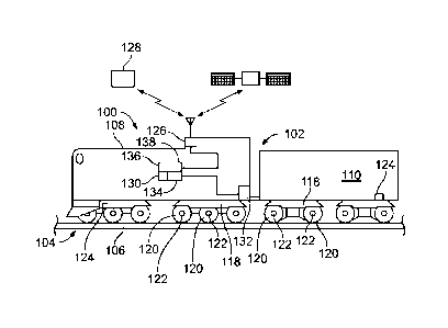
[0010] Figure 1 illustrates a block schematic diagram of a vehicle system;
[0011] Figure 2 illustrates block schematic diagram of a controller;
[0012] Figure 3 illustrates a block schematic diagram of a method of
restricting the movement
of a vehicle system; and
[0013] Figure 4 illustrates vehicle speed over time.
DETAILED DESCRIPTION
3
Date recue / Date received 2021-11-29
[0014] Embodiments of the subject matter described herein relate to
systems and methods
that calculate the speed of a vehicle based on forces acting upon the vehicle
when a wheel slip or
slide is detected. When a potential wheel slip or slide occurs, the system may
use a calculated
vehicle speed until the tachometer speed matches the calculated vehicle speed,
or a positional
moving speed as determined utilizing an off-board source such as a satellite
navigation system.
The calculated speed may be based upon the forces acting on the vehicle,
including route grade,
route curvature, resistive forces, motor forces including tractive forces and
dynamic braking, air
braking, control settings including throttle position and brake pipe pressure
(BPP) drop, etc. By
utilizing calculated speed for braking calculations, when a wheel slip or
slide event is detected,
more accurate braking calculations are achieved.
[0015] A PVC system is a monitoring system utilized by a vehicle system
to allow the
vehicle system to move within a designated restricted manner (such as above a
designated penalty
speed limit, to enter another route segment, etc.) only responsive to receipt
or continued receipt of
one or more signals (e.g., received from off-board the vehicle) that meet
designated criteria, e.g.,
the signals have designated characteristics (e.g., a designated waveform
and/or content), are
received at designated times (or according to other designated time criteria),
and/or under
designated conditions. For example, the vehicle may be automatically prevented
from entering
into another route segment unless a signal is received by the PVC system
indicating that the other
route segment does not include any other vehicles, may be automatically
prevented from moving
at speeds above a speed limit when a route segment has a maintenance crew
present, etc. This is
opposed to 'negative' vehicle monitoring systems where a vehicle is allowed to
move unless a
signal (restricting movement) is received.
[0016] Not all embodiments described herein are limited to rail vehicle
systems, or PVC
systems. For example, one or more embodiments of the detection systems and
methods described
herein can be used in connection with other types of vehicles, such as
automobiles, trucks, buses,
mining vehicles, marine vessels, aircraft, agricultural vehicles, or the like.
As another example,
one or more embodiments can be used with vehicle control systems other than
PVC systems to
change movement of a vehicle. For example, a negative vehicle monitoring
system (e.g. where a
vehicle is allowed to move unless a signal restricting movement is received)
could be utilized to
change the movement of a vehicle.
4
Date recue / Date received 2021-11-29
[0017] Figure 1 illustrates a schematic diagram of one example of a
vehicle system 100
that includes a monitoring system 102. The vehicle system may also travel
along a route 104 on a
trip from a starting or departure location to a destination or arrival
location. The vehicle system
includes at least one propulsion-generating vehicle 108 and, optionally, a non-
propulsion-
generating vehicle 110 that are mechanically connected or interconnected to
one another to travel
together along the route. Alternatively, the vehicle system may be formed of
only a single
propulsion-generating vehicle. In yet another embodiment, the vehicles in the
vehicle system are
logically or virtually coupled together, but not mechanically coupled
together.
[0018] The propulsion-generating vehicle may generate tractive efforts to
propel (for
example, pull or push) the vehicle system along routes. The propulsion-
generating vehicle includes
a propulsion subsystem, such as an engine, one or more traction motors, or the
like, that operate to
generate tractive effort to propel the vehicle system. The propulsion-
generating vehicle also
includes a braking system 112 that generates braking effort to slow or stop
movement of the vehicle
system. Although one propulsion-generating vehicle and one non-propulsion-
generating vehicle
are shown in Figure 1, the vehicle system may include multiple propulsion-
generating vehicles
and/or multiple non-propulsion-generating vehicles.
[0019] In the example of Figure 1, the vehicles of the vehicle system
each include multiple
wheels 120 that engage the route and at least one axle 122 that couples left
and right wheels
together (only the left wheels are shown in Figure 1). Optionally, the wheels
and axles are located
on one or more trucks or bogies 118. Optionally, the trucks may be fixed-axle
trucks, such that the
wheels are rotationally fixed to the axles, so the left wheel rotates the same
speed, amount, and at
the same times as the right wheel. In one embodiment, the vehicle system may
not include axles,
such as in some mining vehicles, electric vehicles, etc.
[0020] Movement of at least one wheel is monitored by a wheel speed
sensor 124 that
detects rotation of the wheel that can be used to determine a sensed moving
speed of the vehicle
system. The wheel speed sensor may be coupled to the wheel, the axle, the
vehicle system, a
wayside device, etc. and positioned to detect characteristics of the wheel
that may be used to
determine the sensed moving speed of the vehicle system. In one example, the
wheel speed sensor
Date recue / Date received 2021-11-29
is a tachometer. In another example, an iterative learning control sensor or
algorithm may be
utilized to determine the sensed moving speed of the vehicle system.
[0021] The monitoring system may further include a wireless communication
system 126
that allows wireless communications between vehicles in the vehicle system
and/or with remote
locations, such as the remote (e.g., dispatch) location 128. The communication
system may include
a receiver and a transmitter, or a transceiver that performs both receiving
and transmitting
functions. The communication system may also include an antenna and associated
circuitry.
[0022] The monitoring system further includes a trip characterization
element 130. The
trip characterization element may provide information about the trip of the
vehicle system along
the route. The trip information may include route characteristics, designated
locations, designated
stopping locations, schedule times, meet-up events, directions along the
route, and the like.
[0023] For example, the route characteristics may include grade,
elevation slow warnings,
environmental conditions (e.g., rain and snow), and curvature information. The
trip information
concerning schedule times may include departure times and arrival times for
the overall trip, times
for reaching designated locations, and/or arrival times, break times (e.g.,
the time that the vehicle
system may be stopped), and departure times at various designated stopping
locations during the
trip. The trip characterization element may also include vehicle control
setting for the trip,
including throttle settings, dynamic braking settings, etc. The trip
characterization element may be
a database stored in an electronic storage device, or memory. The information
in the trip
characterization element 130 may be input via the user interface device by an
operator, may be
automatically uploaded, or may be received remotely via the communication
system. The source
for at least some of the information in the trip characterization element may
be a trip manifest, a
log, or the like.
[0024] In an embodiment, the monitoring system may include a vehicle
characterization
element 134. The vehicle characterization element may provide information
about the make-up of
the vehicle system, such as the type of non-propulsion-generating vehicles
(for example, the
manufacturer, the product number, the materials, etc.), the number of non-
propulsion-generating
vehicles, the weight of non-propulsion-generating vehicles, whether the non-
propulsion-
generating vehicles are consistent (meaning relatively identical in weight and
distribution
6
Date recue / Date received 2021-11-29
throughout the length of the vehicle system) or inconsistent, the type and
weight of cargo, the total
weight of the vehicle system, the number of propulsion-generating vehicles,
the position and
arrangement of propulsion-generating vehicles relative to the non-propulsion-
generating vehicles,
the type of propulsion-generating vehicles (including the manufacturer, the
product number, power
output capabilities, available notch settings, fuel usage rates, etc.), and
the like.
[0025] The vehicle characterization element may be a database stored in
an electronic
storage device, or memory. The information in the vehicle characterization
element may be input
using an input/output (I/O) device (referred to as a user interface device) by
an operator, may be
automatically uploaded, or may be received remotely via the communication
system. The source
for at least some of the information in the vehicle characterization element
may be a vehicle
manifest, a log, or the like.
[0026] The vehicle system may also include a locator device 136. The
locator device may
be positioned on the vehicle system, utilize wayside devices, etc. In one
example, the locator
device is a global navigation satellite system such as a global positioning
system (GPS) that
provides position data related to the vehicle system. Alternatively, the
locator device may be or
may implement WiFi, Bluetooth enabled beacons, near-field communication (NFC),
radio
frequency identification (RFID), QR code, etc. to provide location
information.
[0027] Figure 2 provides a schematic illustration of a controller 200
that may control
operation of a propulsion-generating vehicle. In one example, the controller
represents the
controller in Figure 1. The controller may be a device that includes one or
more processors 202
(microprocessors, integrated circuits, field programmable gate arrays, etc.).
The one or more
processors may determine the speed of the vehicle system based on a sensor
reading, and/or based
on one or more force parameters. Force parameters may represent or be used to
determine a force
on the vehicle system to vary the speed of the vehicle system. Force
parameters may include route
grade, route curvature, resistive forces, motor tractive forces, dynamic
braking, air braking, throttle
position, brake pipe pressure drop, or the like.
[0028] The controller optionally may also include a controller memory
204, which may be
an electronic, computer-readable storage device or medium. The controller
memory may be within
the housing of the controller, or alternatively may be on a separate device
that may be
7
Date recue / Date received 2021-11-29
communicatively coupled to the controller and the one or more processors
therein. By
"communicatively coupled," it is meant that two devices, systems, subsystems,
assemblies,
modules, components, and the like, are joined by one or more wired or wireless
communication
links, such as by one or more conductive (e.g., copper) wires, cables, or
buses; wireless networks;
fiber optic cables, and the like. The controller memory can include a
tangible, non-transitory
computer-readable storage medium that stores data on a temporary or permanent
basis for use by
the one or more processors. The memory may include one or more volatile and/or
non-volatile
memory devices, such as random access memory (RAM), static random access
memory (SRAM),
dynamic RAM (DRAM), another type of RAM, read only memory (ROM), flash memory,
magnetic storage devices (e.g., hard discs, floppy discs, or magnetic tapes),
optical discs, and the
like. The memory may be utilized to store information related to vehicle
parameters, route
parameters, trip parameters, or the like. Vehicle parameters may include
vehicle weight, wheel
diameter, tachometer readings, throttle settings, brake settings, speeds,
brake settings,
accelerations, etc. Route parameters may include route grade, route weather,
route curvature, etc.
Trip parameters may include destination, speed limits for areas, traffic
congestion, break locations,
tunnel locations, or the like.
[0029] The controller may also include a transceiver 206 that may
communicate with a
remote device 208. The transceiver may be a single unit or be a separate
receiver and transmitter.
In one example, the transceiver may only transmit signals. The remote device
208 may be a
dispatch controller, a controller of another vehicle, a second controller
coupled to the vehicle
system, a controller within a wayside device, or the like. In one example, the
remote device is a
PVC system as described herein, and more specifically, in one embodiment a
positive train control
(PTC) system. The PVC system may receive speed information from the
transceiver, determine
and/or calculate the speed of the vehicle system, restrict movement of one or
more vehicle systems
based on a set of rules, etc.
[0030] The controller may also include one or more sensors 210 coupled to
the vehicle
system to detect vehicle parameters, route parameters, trip parameters, or the
like. In one
embodiment, at least one sensor is a wheel speed sensor that detects
information that may be
utilized to calculate a sensed moving speed of the vehicle system. In one
example, the wheel speed
sensor is a tachometer coupled to the wheel. The one or more sensors may also
include a locator
8
Date recue / Date received 2021-11-29
device such as a GPS that provides the location of the vehicle system. The
sensors may be coupled
to the vehicle system, adjacent a vehicle system, or otherwise. For example, a
weather sensor that
is in communication with the one or more processors, even when in a remote
location, may be
considered a sensor of the controller. The one or more sensors may also
include auxiliary sensors
that monitor force parameters related to the vehicle system that may be
utilized to determine a
predicted speed of the vehicle system. In one example, the predicted speed may
be a positional
moving speed, a calculated moving speed, or the like.
[0031] The controller may also include an input device 212 and an output
device 214.
Specifically, the input device may be an interface between an operator and the
one or more
processors. The input device may include a display or touch screen, input
buttons, ports for
receiving memory devices, etc. In this manner, an operator may manually
provide parameters into
the controller, including vehicle parameters, route parameters, and trip
parameters. Similarly, the
output device may present information and data to an operator, or provide
prompts for information
and data. The output device may similarly be a display or touch screen. In
this manner, a display
or touch screen may be an input device and an output device.
[0032] The controller can additionally include a speed regulator unit
216. The speed
regulator unit receives inputs from the sensors, memory, input device, etc.
and makes
determinations regarding the speed of the vehicle. In particular, the speed
regulator unit may
receive inputs from a vehicle characterization element 218 and/or a trip
characterization element
220 that are also part of the controller. In one example, the speed regulator
unit receives input from
a tachometer and determines the speed of the vehicle based on a calculation,
lookup table,
algorithm, or the like to determine the vehicle speed. The speed regulator
unit may also receive or
obtain a threshold rate and threshold amount, and determine changes of rate of
the speed of the
vehicle. Specifically, the speed regulator unit 216 may determine if the
sensed moving speed of
the vehicle system change at a rate that is faster than the threshold rate or
changes by more than a
threshold amount.
[0033] In one example, the threshold rate is 3 miles per hour per second,
such that the
speed regulator unit may determine that the sensed moving speed decelerates or
accelerates more
than 3 miles per hour per second. Such a threshold rate indicates that a wheel
can potentially be
9
Date recue / Date received 2021-11-29
slipping or sliding, and the sensor is detecting the change in wheel rotation
rate only, and not a
change in vehicle system rate. In another example, the threshold amount may be
5 miles per hour
from a determined speed. Specifically, during a trip often a vehicle system is
to maintain a constant
speed during section of the trip. Thus, an increase above or below that speed
in a section may be
indicative of a wheel slip. When used herein, wheel slip refers to any
undesired movement of the
wheel, including wheel slip, wheel slide, or the like. Similarly, the
threshold amount may be 3 mph
from a calculated or predicted speed. Specifically, based on the operational
settings, route inclines
or declines, vehicle system weight, etc., the speed regulator unit may
determine a calculated or
predicted speed of the vehicle system for any given portion of a route. If the
speed determined
from a sensor exceeds the threshold amount from the calculated or predicted
speed, a wheel slip
condition may be presented. In yet another example, the calculated or
predicted speed may be
determined by a remote device, and communicated to the speed regulator unit,
and the threshold
amount may be an amount from such communicated calculated moving speed.
[0034] The speed regulator unit may also determine whether to restrict
the movement of
the vehicle system based on a calculated speed and not based on the sensed
moving speed that is
output from the sensor. In one example, the monitoring system, via the speed
regulator unit,
continuously provides vehicle speed information to a remote device. In one
example, the remote
device is a PVC system that receives similar input from other vehicles systems
traveling the same
or similar routes. Based on the speed information received, the PVC system
determines and
communicates speed restrictions to the speed regulator unit to prevent
collisions, and provide safer
traveling conditions. So, when a potential wheel slip is determined by the
speed regulator unit,
instead of sending the sensed moving speed as determined by a wheel speed
sensor, the speed
regulator unit determines to have the PVC system utilize a calculated speed of
the vehicle.
[0035] In one embodiment, the speed regulator unit calculates the speed
of the vehicle
based on parameters. For example, based on the throttle position, grade of the
route, and weight
of the vehicle, a prediction may be made regarding the speed of the vehicle.
Such a prediction
may be made through an algorithm, mathematical equation, lookup table,
mathematical function,
etc. Alternatively, the PVC system may make the prediction and communicate the
prediction to
the speed regulator unit. The calculated vehicle speed is then the vehicle
speed communicated to
Date recue / Date received 2021-11-29
the PVC system to determine restriction of movement of the vehicle system
based on vehicle
speed.
[0036] After the speed regulator unit determines to communicate the
calculated speed to
the PVC system instead of the sensed vehicle speed, the monitoring system
continues to determine
whether to restrict the movement of the vehicle system based at least on the
sensed moving speed
and not based on the calculated speed. Specifically, once the wheel slip has
been verified, the speed
regulator unit communicates the sensed vehicle speed. In one embodiment, to
verify the wheel
slip, in response to a rate or an amount threshold being exceeded, the one or
more processors
receive global positioning data, and based on the global positioning data, the
positional moving
speed of the vehicle system is continuously determined, and compared to the
sensed vehicle speed.
Once the positional moving speed matches, or is within a tolerance of the
sensed wheel speed, a
determination is made that the wheel either did not slip, or has completed
slipping. In one example,
the tolerance is 2 miles per hour. As a result of the determination, the speed
regulator unit
communicates the sensed vehicle speed again to the PVC system to restrict
movement of the
vehicle system based on the wheel speed sensor.
[0037] Figure 3 illustrates a block diagram of a method 300 of
restricting the movement
of a vehicle system. In one example, the monitoring system of Figure 2 is
utilized to implement
the method.
[0038] At step 302, a sensed moving speed of a vehicle system is
monitored based on
output from a sensor using a monitoring system that may automatically restrict
movement of the
vehicle system based at least on the sensing moving speed that is monitored.
In one example, the
sensor is a wheel speed sensor, and specifically may be a tachometer. The
tachometer detects the
frequency of rotations of the wheel to determine revolutions per minute, that
is utilized to
determine the resulting sensed moving speed of the vehicle.
[0039] In another example, the monitoring system is a PVC system, or a
controller utilizing
PVC system protocols that may be in communication with numerous vehicle
systems that travel
the same or similar routes. Based on the movements of all of the different
vehicle systems the PVC
system restricts the movement of individual vehicle systems to prevent
collisions and improve
safety along the routes. In an embodiment when the vehicle systems are rail
vehicles, and the
11
Date recue / Date received 2021-11-29
monitoring system utilizes PVC system protocols, when a first rail vehicle is
on a first rail, and a
second rail vehicle is on a second rail that converges with the first track,
the monitoring system
monitors the speed of both the first rail vehicle and the second rail vehicle.
If from monitoring the
speed of the first and second rail vehicles a determination is made that the
front of the second rail
vehicle will collide with non-propulsion-generating vehicles at the back end
of the first rail vehicle
when the second rail merges into the first rail, the monitoring system will
automatically reduce the
speed of the second rail vehicle to prevent the collision. By reducing the
speed of the second rail
vehicle, the movement of the second rail vehicle is restricted, thus
preventing collision at the merge
point between the first and second rails.
[0040] In another example, the first rail vehicle and second rail vehicle
may be traveling
along the same track. If the first rail vehicle comes upon standing water on
the track and is forced
to stop, the controller similarly will stop the movement of the second rail
vehicle to prevent the
second rail vehicle from hitting the back end of the first rail vehicle.
[0041] At step 304, a determination is made whether to restrict the
movement of the vehicle
system based at least on a calculated speed and not based on the sensed moving
speed. In particular,
if the threshold rate or threshold amount are not exceeded, then the
monitoring system continues
to monitor the vehicle system, and the sensed moving speed is utilized to
communicate to a PVC
system to restrict the movement of the vehicle. However, if a threshold rate
or threshold amount
is exceeded, then the monitoring system no longer uses the sensed moving speed
and instead begins
to utilize a calculated speed of the vehicle system to communicate to a PVC
system.
[0042] If a determination is made at step 304 to use a calculated speed,
at step 306,
responsive to determining that the sensed moving speed is one or more of
changing at a rate that
is faster than a threshold rate, or changing by more than a threshold amount,
a calculated speed of
the vehicle system is obtained using the monitoring system. In one example,
the sensed moving
speed of a vehicle is monitored using a tachometer. If the wheel slips or
spins, the reading of the
tachometer detects the slip or spin, and does not provide an accurate speed
determination. To
address this concern, the tachometer may be monitored for sudden accelerations
or decelerations
that are indicative of wheel slips and spins. In this manner, a threshold rate
may be 2 miles per
12
Date recue / Date received 2021-11-29
hour per second, whereas a threshold amount may be more the 5 miles per hour
in a 5 second
interval. Both thresholds provide indications of wheel slips or spins.
[0043] The calculated speed of the vehicle in one example is determined
by a PVC system.
The PVC system may be remote to the vehicle system, or on board the vehicle
system. The
calculated speed may be obtained by making a determination, calculation,
predictions, etc. in
response to a threshold being exceeded, or from receiving the calculated speed
from a monitoring
system that continuously determines, calculates, predicts, etc. the predicted
speed. In particular, a
PVC system often continuously determines the calculated speed of the vehicle
by obtaining force
parameters such as route grade, route curvature, resistive forces, motor
tractive forces, dynamic
braking, air braking, throttle position, brake pipe pressure drop, etc. These
parameters may be
monitored by auxiliary sensors, input into the monitoring system, received
from the memory of
the monitoring system, received from a remote device, calculated based on
other parameters, or
the like. Based on the force parameters, the calculated speed may be
determined using an
algorithm, mathematical equation, mathematical function, mathematical model,
computer based
model, lookup table, decision tree, or the like. In this manner, the
monitoring system does not
utilize the sensed moving speed as determined by the wheel sensor to determine
the calculated
speed.
[0044] At step 308, also responsive to determining that the sensed moving
speed is one or
more of changing at a rate that is faster than the threshold rate, or changing
by more than a
threshold amount at step 304, a determination is made whether a wheel slip
occurred. In particular,
the threshold rate and threshold amount are presented to attempt to identify
potential wheel slip,
and mitigate the effect of a wheel slip.
[0045] In one example, to determine if a wheel slip has occurred, the
vehicle system
utilizes position data to determine a positional moving speed of the vehicle
system. In one
embodiment the monitoring system either includes or is in communication with a
global
positioning system that detects the location of the vehicle system. Then based
on the distance the
vehicle system has traveled over a given period, the positional moving speed
of the vehicle may
be determined. In the example, the positional moving speed of the vehicle
system is compared to
the sensed moving speed of the vehicle system. If the positional moving speed
and sensed moving
13
Date recue / Date received 2021-11-29
speed match or are within a tolerance of one another, a slip has not occurred.
Alternatively, if the
positional moving speed and sensed moving speed do not match or are not within
a tolerance of
one another, then a determination is made that a wheel slip has occurred.
[0046] In another example, to determine if a wheel slip has occurred, the
vehicle system
compares the calculated speed and the sensed moving speed determined utilizing
the wheel sensor.
If the calculated speed does not match, or is not within a tolerance of the
sensed moving speed
determined utilizing the sensor, a wheel slip is determined to occur. In this
manner, if a GPS signal
is lost or cannot be found, a slip event can still be determined.
[0047] At step 310, the monitoring system returns to determining whether
to restrict the
movement of the vehicle system based at least on the sensed moving speed.
After the determination
of the wheel slip, if no wheel slip has occurred, the monitoring system
switches back to restricting
movement of the vehicle system by using the sensed moving speed as determined
by utilizing the
sensor to communicate to a PVC system. Alternatively, if a wheel slip is
determined, the
monitoring system continues to compare the sensed moving speed to a predicted
speed such as a
positional moving speed, or the calculated moving speed. Once these moving
speeds converge, or
are within a tolerance of one another, an indication that the wheel slip is
over is provided. As a
result, the monitoring system returns to using the sensed moving speed of the
sensor to restrict
movement, and thus returns to determining whether to restrict the movement of
the vehicle system
based at least on the sensed moving speed. In particular, the monitoring
system continues to
monitor whether a threshold rate or threshold amount is exceeded indicating
another potential
wheel slip has occurred.
[0048] Figure 4 illustrates a graph 400 plotting sensed moving speed 402
over time 404 to
illustrate the speed of a vehicle during a wheel slip and how the system of
Fig. 2 and method of
Fig. 3 can improve speed data provided for the restriction of movement of the
vehicle system. Line
406 illustrates the actual speed of the vehicle system, while line 408
illustrates the wheel tach
(sensor) speed, or sensed moving speed, line 409 illustrates a calculated
speed, and line 410
illustrates a current method used to compensate for wheel slip where the last
sensed moving speed
recorded before the potential wheel slip (threshold rate or threshold amount
is exceeded) is
detected and used as the speed for determining restriction of movement of the
vehicle.
14
Date recue / Date received 2021-11-29
[0049] In this example, a wheel slip occurs at point 412. As illustrated,
at the wheel slip
point the wheel tach speed suddenly increases compared to the actual speed of
the vehicle system
as the wheel freely spins. Then the sensed moving speed (e.g. tach speed)
suddenly decreases
compared to the actual speed of the vehicle as the wheel reengages, and
finally corresponds back
to the actual speed at point 414. When not mitigated, this speed fluctuation
results in a controller,
such as a PVC system, using incorrect speed information in restricting
movement of the vehicle
system. Such incorrect calculation can result in a reduction of speed of a
vehicle system when such
reduction is unnecessary, delaying travel, inefficient fuel consumption, and
increase safety
concerns.
[0050] Additionally, while using the last reported sensed moving speed as
the speed to
provide a PVC system and restrict the speed of the vehicle accordingly
mitigates some of the speed
variance of the tach speed, inefficiencies remain. Specifically, in this
example, the actual speed of
the vehicle is increasing, resulting in the incorrect speed being used to
restrict movement until the
slip is accounted for. Similarly, when the actual speed of the vehicle system
is decreasing similar
errors occur. In contrast, the calculated speed closely follows the actual
speed of the vehicle
through the entire wheel slip. Thus, while during non-wheel slip travel, the
sensed moving speed
may be more accurate than the calculated speed, the calculated speed is far
more accurate than the
sensed moving speed, or a last recorded speed during a wheel slip event. This
improves calculation
of a PVC system, improving travel efficiencies. Additionally, by using a
calculated speed, if
position data is unavailable because the vehicle system is in a tunnel, or in
an area with bad
reception, the wheel slip may still be identified. This again result in more
accurate speed
determination for the vehicle system.
[0051] In addition, when using the last reported sensed moving speed to
mitigate the
inaccuracies of the sensed moving speed during a slip or slide event, if the
held last reported speed
deviates too far from the actual speed, then a PVC system may continuously see
an acceleration
above the slip or slide threshold. Consequently, recovery from the slip or
slide event does not
occur, and mitigation simply does not occur. Specifically, a determined
period, that in one example
is ten seconds, may be provided for a matching of the last held reported speed
and the sensed
moving speed. Once the determined period lapses, the sensed moving speed is
automatically
utilized, even though a slip or slide event is not complete. By using the
calculated speed, the
Date recue / Date received 2021-11-29
determined period may be increased, because the calculated speed and actual
speed of the vehicle
provide far less error than holding a last know speed. This allows more time
for the actual speed
of the vehicle and sensed moving speed to match, causing recovery to be much
more likely, and
can allow the PVC system to remain active. Furthermore, using the calculated
speed can allow
recovery from a slip or slide event even when one sensor is unavailable such
as a loss of GPS. If
the predicted speed and sensed moving speed begin to match again the system
can clear the slip or
slide event even when out of GPS coverage, such as while in a tunnel, or if
the slip or slide occurred
during acceleration or deceleration.
[0052] In all, the system and method allow a PVC system to follow the
calculated speed
throughout the slip or slide event. The approach allows the PVC system to
reduce the errors that
are inaccurate for an accelerating or decelerating vehicle system and can lead
to inaccuracy of the
braking calculations. Specifically, the inaccurate speeds can result in
unnecessary braking causing
targeted travel times, fuel consumption, emissions, etc. to be missed. By
using the predicted speed
to determine the actual speed during the wheel slip event, a speed can be used
by the PVC system
that has a much higher probability of being correct than the sensed moving
speed or holding the
last known speed. This may allow the PVC system to ride through a longer wheel
slip event and/or
recover more quickly when the predicted speed begins to match the speed inputs
again. As a result,
the system and method benefit the PVC system and reduces route failures due to
loss of speed.
Additionally, the system and method improve navigation functionality and
accuracy such that
position error is reduced.
[0053] In one or more embodiments, a monitoring system is provided that
may include a
sensor that may output a sensed moving speed of a vehicle system. The
monitoring system may
also include one or more processors in communication with the sensor and may
automatically
restrict movement of a vehicle system based at least in part on the sensed
moving speed. The one
or more processors may also determine whether to restrict the movement of the
vehicle system
based at least in part on a calculated speed that is not based on the sensed
moving speed, and
prepare to restrict movement of the vehicle system based at least in part on
the calculated speed
responsive to determining that the sensed moving speed is one or both of
changing at a rate that is
faster than a determined threshold rate, and changing by more than a
determined threshold amount.
The one or more processors may also determine whether a wheel slip occurred
responsive to
16
Date recue / Date received 2021-11-29
preparation to restrict movement of the vehicle speed, and return to
determining whether to restrict
the movement of the vehicle system responsive to determining that the wheel
slip occurred.
[0054] Optionally, the one or more processors may also compare the sensed
moving speed
to either of the calculated speed or a positional moving speed determined at
least in part from
position data, and not restrict the movement of the vehicle speed based on a
determination the
wheel slip occurred. In one aspect, the calculated speed may match the sensed
moving speed when
the calculated speed is within a determined tolerance value of the sensed
moving speed, or the
positional moving speed matches the moving speed when the positional moving
speed is within a
determined tolerance value of the sensed moving speed. In another aspect, the
one or more
processors may also obtain the position data from an off-board source. In one
example, the one or
more processors may also brake the vehicle responsive to the preparation to
restrict the movement
of the vehicle speed.
[0055] Optionally, the sensor may be at least one of a tachometer coupled
to a wheel of
the vehicle, an accelerometer, or an iterative learning control sensor. In
another aspect, the
calculated speed of the vehicle system is based at least in part a force
parameter associated with
the vehicle system. In another example, the one or more processors may also
obtain the at least
one force parameter from at least one of an auxiliary sensor, a memory, a
positive vehicle
monitoring system, or an input device. In one embodiment, the at least one
force parameter may
be one of route grade, route curvature, resistive forces, motor tractive
forces, dynamic braking, air
braking, throttle position, or brake pipe pressure drop.
[0056] In one or more embodiments, a monitoring system is provided that
may include a
sensor and one or more processors. The one or more processors may monitor a
sensed moving
speed of a vehicle system based on output from the sensor, and automatically
restrict movement
of a vehicle system based at least in part on the sensed moving speed. The one
or more processors
may also determine whether to restrict the movement of the vehicle system
based at least in part
on a calculated speed that is not based on the sensed moving speed. The one or
more processors
may also prepare to restrict movement of the vehicle system based at least in
part on the calculated
speed responsive to determining that the sensed moving speed is one or both of
changing at a rate
that is faster than a determined threshold rate, and changing by more than a
determined threshold
17
Date recue / Date received 2021-11-29
amount. The one or more processors may also determine whether a wheel slip
occurred responsive
to preparation to restrict movement of the vehicle speed by comparing the
moving speed of the
vehicle system based on the output from the sensor to either one of the
calculated speed or a
positional moving speed, and not restrict the movement of the vehicle speed
based on a
determination the wheel slip occurred.
[0057] Optionally, the calculated speed is not based on the moving speed
based on the
output from the sensor. In one aspect, the calculated speed may match the
moving speed based on
the output from the sensor when the calculated speed is within a tolerance of
the moving speed
based on the output from the sensor, or wherein the positional moving speed
matches the moving
speed based on the output from the sensor when the positional moving speed is
within a tolerance
of the moving speed based on the output from the sensor. In another aspect,
the one or more
processors may also obtain the position data from an off-board source.
[0058] In one or more embodiments a method is provided that may include
sensing, with
a sensor, a sensed moving speed of a vehicle system. The method may also
include automatically
restricting movement of the vehicle system based at least in part on the
sensed moving speed, and
determining whether to restrict the movement of the vehicle system based at
least in part on a
calculated speed that is not based on the sensed moving speed. The method may
also include
preparing to restrict movement of the vehicle system based at least in part on
the calculated speed
responsive to determining that the sensed moving speed is one or both of
changing at a rate that is
faster than a determined threshold rate, and changing by more than a
determined threshold amount.
The method may also include determining whether a wheel slip occurred
responsive to preparation
to restrict movement of the vehicle speed, and returning to determining
whether to restrict the
movement of the vehicle system responsive to determining that the wheel slip
occurred.
[0059] Optionally, returning to determining whether to restrict the
movement of the
vehicle system responsive to determining that the wheel slip occurred may
comprises comparing
the sensed moving speed of the vehicle system to either one of the calculated
speed or a positional
moving speed. In one aspect, comparing the sensed moving speed of the vehicle
system to either
one of the calculated speed or the positional moving speed may include
matching either one of
sensed moving speed to the calculated speed, or the sensed moving speed to the
positional moving
18
Date recue / Date received 2021-11-29
speed. In another aspect, the calculated speed may match the sensed moving
speed when the
calculated speed is within a tolerance of the sensed moving speed, or wherein
the positional
moving speed matches the sensed moving speed when the positional moving speed
is within a
tolerance of the sensed moving speed. In another aspect, the position data may
be obtained from
an off-board source. In one example, the calculated speed of the vehicle
system may be based on
at least one force parameter associated with the vehicle system. In another
example, the at least
one force parameter may be one of route grade, route curvature, resistive
forces, motor tractive
forces, dynamic braking, air braking, throttle position, or brake pipe
pressure drop.
[0060]
In one embodiment, the control system, or controller, may have a local data
collection
system deployed and may use machine learning to enable derivation-based
learning outcomes. The
controller may learn from and make decisions on a set of data (including data
provided by the
various sensors), by making data-driven predictions and adapting according to
the set of data. In
embodiments, machine learning may involve performing a plurality of machine
learning tasks by
machine learning systems, such as supervised learning, unsupervised learning,
and reinforcement
learning. Supervised learning may include presenting a set of example inputs
and desired outputs
to the machine learning systems. Unsupervised learning may include the
learning algorithm
structuring its input by methods such as pattern detection and/or feature
learning. Reinforcement
learning may include the machine learning systems performing in a dynamic
environment and then
providing feedback about correct and incorrect decisions. In examples, machine
learning may
include a plurality of other tasks based on an output of the machine learning
system. The tasks
may be machine learning problems such as classification, regression,
clustering, density
estimation, dimensionality reduction, anomaly detection, and the like. In
examples, machine
learning may include a plurality of mathematical and statistical techniques.
The machine learning
algorithms may include decision tree based learning, association rule
learning, deep learning,
artificial neural networks, genetic learning algorithms, inductive logic
programming, support
vector machines (SVMs), Bayesian network, reinforcement learning,
representation learning, rule-
based machine learning, sparse dictionary learning, similarity and metric
learning, learning
classifier systems (LCS), logistic regression, random forest, K-Means,
gradient boost, K-nearest
neighbors (KNN), a priori algorithms, and the like. In embodiments, certain
machine learning
algorithms may be used (e.g., for solving both constrained and unconstrained
optimization
19
Date recue / Date received 2021-11-29
problems that may be based on natural selection). In an example, the algorithm
may be used to
address problems of mixed integer programming, where some components are
restricted to being
integer-valued. Algorithms and machine learning techniques and systems may be
used in
computational intelligence systems, computer vision, Natural Language
Processing (NLP),
recommender systems, reinforcement learning, building graphical models, and
the like. In an
example, machine learning may be used for vehicle performance and control,
behavior analytics,
and the like.
[0061]
In one embodiment, controller may include a policy engine that may apply one
or more
policies. These policies may be based at least in part on characteristics of a
given item of equipment
or environment. With respect to control policies, a neural network can receive
input of a number
of environmental and task-related parameters. The neural network can be
trained to generate an
output based on these inputs, with the output representing an action or
sequence of actions that the
vehicle should take to accomplish the trip plan. During operation of one
embodiment, a
determination can occur by processing the inputs through the parameters of the
neural network to
generate a value at the output node designating that action as the desired
action. This action may
translate into a signal that causes the vehicle to operate. This may be
accomplished via back-
propagation, feed forward processes, closed loop feedback, or open loop
feedback. Alternatively,
rather than using backpropagation, the machine learning system of the
controller may use
evolution strategies techniques to tune various parameters of the artificial
neural network. The
controller may use neural network architectures with functions that may not
always be solvable
using backpropagation, for example functions that are non-convex. In one
embodiment, the neural
network has a set of parameters representing weights of its node connections.
A number of copies
of this network are generated and then different adjustments to the parameters
are made, and
simulations are done. Once the output from the various models are obtained,
they may be evaluated
on their performance using a determined success metric. The best model is
selected, and the
vehicle controller executes that plan to achieve the desired input data to
minor the predicted best
outcome scenario. Additionally, the success metric may be a combination of the
optimized
outcomes. These may be weighed relative to each other.
[0062]
As used herein, the terms "processor" and "computer," and related terms, e.g.,
"processing device," "computing device," and "controller" may be not limited
to just those
Date recue / Date received 2021-11-29
integrated circuits referred to in the art as a computer, but refer to a
microcontroller, a
microcomputer, a programmable logic controller (PLC), field programmable gate
array, and
application specific integrated circuit, and other programmable circuits.
Suitable memory may
include, for example, a computer-readable medium. A computer-readable medium
may be, for
example, a random-access memory (RAM), a computer-readable non-volatile
medium, such as a
flash memory. The term "non-transitory computer-readable media" represents a
tangible
computer-based device implemented for short-term and long-term storage of
information, such as,
computer-readable instructions, data structures, program modules and sub-
modules, or other data
in any device. Therefore, the methods described herein may be encoded as
executable instructions
embodied in a tangible, non-transitory, computer-readable medium, including,
without limitation,
a storage device and/or a memory device. Such instructions, when executed by a
processor, cause
the processor to perform at least a portion of the methods described herein.
As such, the term
includes tangible, computer-readable media, including, without limitation, non-
transitory
computer storage devices, including without limitation, volatile and non-
volatile media, and
removable and non-removable media such as firmware, physical and virtual
storage, CD-ROMS,
DVDs, and other digital sources, such as a network or the Internet.
[0063] The singular forms "a", "an", and "the" include plural references
unless the context
clearly dictates otherwise. "Optional" or "optionally" means that the
subsequently described event
or circumstance may or may not occur, and that the description may include
instances where the
event occurs and instances where it does not. Approximating language, as used
herein throughout
the specification and claims, may be applied to modify any quantitative
representation that could
permissibly vary without resulting in a change in the basic function to which
it may be related.
Accordingly, a value modified by a term or terms, such as "about,"
"substantially," and
"approximately," may be not to be limited to the precise value specified. In
at least some instances,
the approximating language may correspond to the precision of an instrument
for measuring the
value. Here and throughout the specification and claims, range limitations may
be combined and/or
interchanged, such ranges may be identified and include all the sub-ranges
contained therein unless
context or language indicates otherwise.
[0064] This written description uses examples to disclose the
embodiments, including the
best mode, and to enable a person of ordinary skill in the art to practice the
embodiments, including
21
Date recue / Date received 2021-11-29
making and using any devices or systems and performing any incorporated
methods. The claims
define the patentable scope of the disclosure, and include other examples that
occur to those of
ordinary skill in the art. Such other examples are intended to be within the
scope of the claims if
they have structural elements that do not differ from the literal language of
the claims, or if they
include equivalent structural elements with insubstantial differences from the
literal language of
the claims.
22
Date recue / Date received 2021-11-29