Note : Les descriptions sont présentées dans la langue officielle dans laquelle elles ont été soumises.
1
INTEGRATED HEATING SYSTEMS FOR HEATING STARTUP FLUID AND SOLVENT
IN SOLVENT-ASSISTED HYDROCARBON RECOVERY PROCESSES
TECHNICAL FIELD
[001] The technical field generally relates to processes for in situ
recovery of
hydrocarbons, such as mobilizing bitumen from bitumen-containing reservoirs.
In
particular, the technical field relates to techniques for heating and
circulating fluids for
enhancing hydrocarbon recovery which can involve mobilizing hydrocarbons such
as
bitumen during solvent-assisted recovery processes. The technical field also
relates to
enhanced startup of solvent-assisted recovery processes.
BACKGROUND
[002] There are various techniques for performing in situ recovery of heavy
hydrocarbons, such as heavy oil and/or bitumen, from heavy hydrocarbon-
containing
reservoirs. Some techniques include Steam-Assisted Gravity Drainage (SAGD)
recovery
processes where steam is injected into the heavy hydrocarbon-containing
reservoir to
help mobilize the bitumen for subsequent recovery. Other techniques include
solvent-
assisted recovery processes that can have similarities with conventional SAGD,
although
solvent is injected into the heavy hydrocarbon-containing reservoir instead of
or along
with steam.
[003] In an example of a solvent-assisted recovery process, a pair of
horizontal
wells including an upper injection well and a lower production well can be
provided in the
heavy hydrocarbon-bearing reservoir, which can be an oil sands reservoir.
Prior to the
implementation of the solvent-assisted recovery process, the region between
the
injection well and the production well, i.e., the interwell region, is
characterized by
various levels of hydrocarbon saturation and fluid mobility, and will
generally include a
region having high saturation of hydrocarbons and limited fluid mobility. A
startup
process can be implemented to increase the mobility of the hydrocarbons in the
interwell
region, for instance by warming the interwell region using various methods,
such as
using electric resistive heaters, circulating hot fluids such as steam, or
injecting fluids
into the hydrocarbon-bearing reservoir.
Date recue / Date received 2021-12-03
2
[004] Once fluid communication is established in the region between the
injection
well and the production well, injection of a mobilizing fluid can promote
growth of an
extraction chamber around the injection well. The extraction chamber
eventually extends
upwardly and outwardly from the injection well within the reservoir as the
mobilized
hydrocarbons flow toward the production well mainly due to gravity forces.
Over time, a
production fluid including the mobilized hydrocarbons and a portion of the
mobilizing fluid
is recovered to the surface. The extraction chamber can be formed using
various
mobilizing fluids, such as steam, various hydrocarbon or organic solvents, and
combinations thereof.
[005] When a solvent is used as a mobilizing fluid during a solvent-
assisted
recovery process, heating the solvent prior to injection into a bitumen-
containing
reservoir can facilitate dissolving and mobilizing bitumen. However,
conventional
methods used for heating solvent can pose various challenges. For instance,
direct
heating of a solvent with a fuel-burning heater can be problematic in the
event of a leak.
Furthermore, conventional methods for heating a solvent can involve the use of
dedicated heating equipment at surface that is different than the equipment
used to
produce steam during a startup phase, which can contribute to increased
capital costs.
Thus, the heating of different fluids during the startup phase and the
production phase
can typically involve multiple heating units provided at surface that each
work to heat the
various fluids used to facilitate mobilization of the heavy hydrocarbons.
[006] These challenges related to heating and mobilizing heavy hydrocarbons
during the different stages of in situ recovery provide a need for further
technological
developments in this field.
SUMMARY
[007] In accordance with one aspect, there is provided a process for
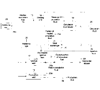
recovering
hydrocarbons from a hydrocarbon-containing reservoir using a well pair
comprising an
injection well overlying a production well, the process comprising: heating a
circulation
fluid using a heating unit located at surface to produce a heated circulation
fluid;
circulating the heated circulation fluid via a circulation system deployed in
at least one of
the injection well and the production well to heat the hydrocarbons
surrounding the at
least one of the injection well and the production well; pre-heating an
injection fluid using
Date recue / Date received 2021-12-03
3
the heating unit to produce a pre-heated injection fluid; introducing the pre-
heated
injection fluid into the hydrocarbon-containing reservoir via an injection
tubing string
provided in the injection well to dissolve and mobilize the hydrocarbons; and
recovering
a production fluid comprising diluted hydrocarbons via the production well.
[008] In some implementations, circulating the heated circulation fluid
into the at
least one of the injection well and the production well comprises: introducing
the heated
circulation fluid into the circulation system; circulating the heated
circulation fluid in the
circulation system; and supplying a return circulation fluid back to the
heating unit.
[009] In some implementations, the process further comprises heating the
return
circulation fluid to produce a heated return circulation fluid, the heated
return circulation
fluid corresponding to the heated circulation fluid.
[0010] In some implementations, pre-heating the injection fluid using the
heating unit
comprises supplying the heated circulation fluid and the injection fluid to a
heat
exchanger to produce the pre-heated injection fluid.
[0011] In some implementations, pre-heating the injection fluid using the
heating unit
comprises supplying the injection fluid and a portion of the heated
circulation fluid to a
heat exchanger to produce the pre-heated injection fluid.
[0012] In some implementations, pre-heating the injection fluid using the
heating unit
comprises supplying the injection fluid and substantially all of the heated
circulation fluid
to a heat exchanger to produce the pre-heated injection fluid.
[0013] In some implementations, the circulation system comprises a closed-
loop
system.
[0014] In some implementations, the circulation system comprises an open-
loop
system.
[0015] In some implementations, the circulation system comprises a dual
mode
circulation system operable in a closed-loop mode and an open-loop mode.
[0016] In some implementations, circulating the heated circulation fluid
is performed
in the injection well.
Date recue / Date received 2021-12-03
4
[0017] In some implementations, the process further comprises heating the
pre-
heated injection fluid travelling downhole in the injection well while the
heated circulation
fluid is being circulated in the injection well to further heat the pre-heated
injection fluid.
[0018] In some implementations, the heating unit is provided at a well
pad.
[0019] In some implementations, the heating unit is provided at a central
processing
facility.
[0020] In some implementations, the heating unit is configured to supply
heat to the
well pair and to at least one additional well pair of the well pad.
[0021] In some implementations, the heating unit is configured to supply
heat to the
well pair and to at least one additional well pair of an additional well pad.
[0022] In some implementations, the process further comprises introducing
the
heated circulation fluid into the at least one additional well pair.
[0023] In some implementations, the process further comprises monitoring
respective
heat requirements for the well pairs and the at least one additional well
pair, and
adjusting an injection rate of the pre-heated injection fluid into a
corresponding injection
well of the well pair and the at least one additional well pair based on the
respective heat
requirements.
[0024] In some implementations, the process further comprises monitoring a
corresponding stage of production for each of the well pair and the at least
one
additional well pair, and adjusting an injection rate of the pre-heated
injection fluid into a
corresponding injection well of the well pair and the at least one additional
well pair
based on the corresponding stage of production.
[0025] In some implementations, the process further comprises monitoring
an
available heating capacity of the heating unit, wherein the circulation fluid
is heated and
circulated in a corresponding injection well of the well pair and the at least
one additional
well pair based on the available capacity of the heating unit.
Date recue / Date received 2021-12-03
5
[0026] In some implementations, the process further comprises adjusting at
least one
of heating the circulation fluid, circulating the heated circulation fluid,
pre-heating the
injection fluid, and injecting the pre-heated injection fluid based on the
monitoring.
[0027] In some implementations, the at least one of the injection well and
the
production well is the injection well and the production well, and the process
further
comprises removing the circulation system from the production well following
completion
of a startup phase.
[0028] In some implementations, the heated circulation fluid comprises
steam.
[0029] In some implementations, the heating unit comprises a steam
generator.
[0030] In some implementations, the steam generator comprises at least one
of a
once-through steam generator (OTSG), a drum boiler, and a direct-fired steam
generator
(DFSG).
[0031] In some implementations, the process further comprises supplying
water to
the heating unit for producing the steam.
[0032] In some implementations, the injection fluid comprises a solvent.
[0033] In some implementations, the solvent comprises a paraffinic
solvent.
[0034] In some implementations, the solvent comprises pentane.
[0035] In some implementations, the solvent comprises butane.
[0036] In some implementations, the solvent comprises propane.
[0037] In some implementations, the hydrocarbons comprise bitumen and/or
heavy
oil.
[0038] In accordance with another aspect, there is provided a process for
recovering
hydrocarbons from a hydrocarbon-containing reservoir using a well pair
comprising an
injection well overlying a production well, the process comprising: heating a
circulation
fluid using a heating unit located at a surface to produce a heated
circulation fluid;
circulating the heated circulation fluid in a closed-loop system provided in
at least one of
Date recue / Date received 2021-12-03
6
the injection well and the production well to heat the hydrocarbons
surrounding the at
least one of the injection well and the production well; supplying a return
circulation fluid
from the closed-loop system back to the heating unit for re-heating to produce
the
heated circulation fluid; pre-heating an injection fluid using the heated
circulation fluid to
produce a pre-heated injection fluid; injecting the pre-heated injection fluid
into the
hydrocarbon-containing reservoir through the injection well to dissolve and
mobilize the
hydrocarbon; and recovering a production fluid comprising diluted hydrocarbons
via the
production well.
[0039] In some implementations, the closed-loop system is provided in the
injection
well.
[0040] In some implementations, the heated circulation fluid is further
circulated in an
additional closed-loop system provided in the production well.
[0041] In some implementations, the process further comprises removing the
additional closed-loop system from the production well after the return
circulation fluid
has been supplied back to the heating unit following completion of a startup
phase.
[0042] In some implementations, pre-heating the injection fluid using the
heating unit
comprises supplying the heated circulation fluid and the injection fluid to a
heat
exchanger to produce the pre-heated injection fluid.
[0043] In some implementations, the process further comprises heating the
pre-
heated injection fluid travelling downhole in the injection well while the
heated circulation
fluid is being circulated in the injection well to further heat the pre-heated
injection fluid.
[0044] In some implementations, the heated circulation fluid comprises
steam.
[0045] In some implementations, the heating unit comprises a steam
generator.
[0046] In some implementations, the steam generator comprises at least one
of a
once-through steam generator (OTSG), a drum boiler, and a direct-fired steam
generator
(DFSG).
[0047] In some implementations, the injection fluid comprises a solvent.
Date recue / Date received 2021-12-03
7
[0048] In some implementations, the hydrocarbons comprise bitumen and/or
heavy
oil.
[0049] In accordance with another aspect, there is provided an integrated
heating
system for recovering hydrocarbons from a hydrocarbon-containing reservoir
using a
well pair comprising an injection well overlying a production well, the
integrated heating
system comprising: a heating unit located at surface and configured to heat a
circulation
fluid to produce a heated circulation fluid and to pre-heat an injection fluid
to produce a
pre-heated injection fluid; a closed-loop system in fluid communication with
the heating
unit and positionable in at least one of the injection well and the production
well to heat
hydrocarbons surrounding the at least one of the injection well and the
production well,
the closed-loop system comprising an introduction tubing string and a return
tubing string
in fluid communication with each other; and an injection tubing string in
fluid
communication with the heating unit and positionable along at least a portion
of the
injection well, the injection tubing string being configured for injecting the
pre-heated
injection fluid into the hydrocarbon-containing reservoir to dissolve and
mobilize
hydrocarbon.
[0050] In some implementations, the heating unit comprises a heat
exchanger
configured to transfer heat from at least a portion of the heated circulation
fluid to the
injection fluid.
[0051] In some implementations, the introduction tubing string is arranged
within the
return tubing string and an inner annulus is defined between the introduction
tubing
string and the return tubing string, and wherein the introduction tubing
string comprises
an open end near a toe of the at least one well and the return tubing
comprises a closed
end near the toe of the at least one of the injection well and the production
well.
[0052] In some implementations, the return tubing string is arranged
within the
introduction tubing string and an inner annulus is defined between the
introduction tubing
string and the return tubing string, and wherein the return tubing string
comprises an
open end near a toe of the at least one well and the introduction tubing
comprises a
closed end near the toe of the at least one of the injection well and the
production well.
Date recue / Date received 2021-12-03
8
[0053] In some implementations, the integrated heating system further
comprises a
fluid inflow control device positioned proximate to the open end to control a
rate at which
the heated circulation fluid is introduced into the inner annulus.
[0054] In some implementations, the closed-loop system further comprises
an outer
tubing string, wherein the introduction tubing string and the return tubing
string are
arranged inside the outer tubing string.
[0055] In some implementations, the integrated heating system further
comprises
insulation disposed around at least one of the introduction tubing string and
the return
tubing string.
[0056] In some implementations, the at least one of the introduction
tubing string and
the return tubing string comprises a vacuum insulated tubing.
[0057] In some implementations, the closed-loop system is positioned in
the injection
well adjacent to at least a portion of the injection tubing string and is
configured to
provide indirect heat to the pre-heated injection fluid.
[0058] In some implementations, the closed-loop system is provided inside
the
injection tubing string, thereby forming an intermediate annulus between an
outer
surface of the closed-loop system and the injection tubing string.
[0059] In some implementations, the injection tubing string comprises
outlets along a
length thereof for injecting the pre-heated injection fluid at multiple
locations along the
injection well.
[0060] In some implementations, the outlets comprise nozzles.
[0061] In some implementations, wherein the heating unit further comprises
a steam
generator to produce steam as the heated circulation fluid.
[0062] In some implementations, the steam generator comprises at least one
of a
once-through steam generator (OTSG), a drum boiler, and a direct-fired steam
generator
(DFSG).
Date recue / Date received 2021-12-03
9
[0063] In some implementations, the hydrocarbons comprise bitumen and/or
heavy
oil.
[0064] In accordance with another aspect, there is provided an integrated
heating
system for mobilizing hydrocarbons in a hydrocarbon-containing reservoir using
a well
pair comprising an injection well overlying a production well, the system
comprising: a
heating unit located at surface, the heating unit comprising: a circulation
fluid heater
configured to heat a circulation fluid to produce a heated circulation fluid;
and a heat
exchanger configured to receive the heated circulation fluid as a heat
exchange fluid to
heat an injection fluid via transfer of heat from the heated circulation fluid
to the injection
fluid to produce a pre-heated injection fluid; an injection tubing string
positionable along
at least a portion of the injection well and configured to be in fluid
communication with
the heat exchanger for injecting the pre-heated injection fluid into the
hydrocarbon-
containing reservoir; and a closed-loop system positionable proximal to the
injection
tubing string in the injection well, the closed-loop system comprising an
introduction
tubing string and a return tubing string in fluid communication with each
other, the
introduction tubing string being configured to be in fluid communication with
the
circulation fluid heater to receive the heated circulation fluid and the
return tubing string
being configured to be in fluid communication with the circulation fluid
heater to supply a
return circulation fluid thereto.
[0065] In some implementations, the integrated heating system further
comprising an
additional closed-loop system comprising an additional introduction tubing
string and an
additional return tubing string, wherein the additional closed-loop system is
configured to
be arranged in the production well and the additional introduction tubing
string is in fluid
communication with the heating unit to receive the heated circulation fluid
and the
additional return tubing string is in fluid communication with the heating
unit to supply the
return circulation fluid to the heating unit.
[0066] In some implementations, the closed-loop system is arranged within
the
injection tubing string and an outer wall of the closed-loop system defines an
outer
annulus with the injection tubing string and wherein the outer annulus is
configured to
receive the pre-heated injection fluid.
Date recue / Date received 2021-12-03
10
[0067] In some implementations, the hydrocarbons comprise bitumen and/or
heavy
oil.
BRIEF DESCRIPTION OF THE DRAWINGS
[0068] The attached figures illustrate various features, aspects and
implementations
of the technology described herein.
[0069] Fig 1A is a side view schematic of a well pair during the startup
phase,
including a closed-loop system in both wellbores.
[0070] Fig 1B is a side view schematic of a well pair configured for
operation during a
production phase, with a closed-loop system being provided in one of the
wellbores.
[0071] Fig 2A is an example of a process flow of an in situ hydrocarbon
recovery
operation.
[0072] Fig 2B is another example of a process flow of an in situ
hydrocarbon
recovery operation.
[0073] Fig 2C is an example of a process flow of an in situ hydrocarbon
recovery
operation for a plurality of well pairs in two well pads.
[0074] Fig 3A is a side view schematic of a completion assembly in an
injection well
according to another implementation.
[0075] Fig 3B is a cross-sectional view of the completion assembly of Fig
3A.
[0076] Fig 4A is a side view schematic of a completion assembly in an
injection well
according to another implementation.
[0077] Fig 4B is a cross-sectional view of the completion assembly of Fig
4A.
[0078] Fig 5A is a side view schematic of a completion assembly in an
injection well
of a well pair.
[0079] Fig 5B is a cross-sectional view of the completion assembly of Fig
5A.
Date recue / Date received 2021-12-03
11
[0080] Fig 6 is a side view schematic of a well pair during the startup
phase,
including a completion assembly in both wellbores.
[0081] Fig 7 is a side view schematic of a well pair during the production
phase,
including a completion assembly according to another implementation in the
injection
well.
[0082] Fig 8A is a side view schematic of a completion assembly according
to
another implementation in an injection well.
[0083] Fig 8B is a cross-sectional view of the completion assembly in Fig
8A.
DETAILED DESCRIPTION
[0084] Techniques described herein relate to processes for mobilizing
hydrocarbons,
such as heavy hydrocarbons which can include bitumen or heavy oil, present in
a
hydrocarbon-containing reservoir, in the context of in situ hydrocarbon
recovery
operations using a well assembly. The well assembly can be a well pair that
includes an
injection well and a production well. Various aspects of the process can be
used as part
of a startup phase, as well as during subsequent stages of hydrocarbon
recovery
operations such as during the production phase where mobilized hydrocarbons
are
recovered to the surface. While implementations of the process will be
discussed mainly
in association with bitumen recovery, it is noted that various hydrocarbons
can be
recovered using techniques described herein.
[0085] The process involves the use of an integrated heating system that is
configured to heat a circulating fluid and a mobilizing fluid. The techniques
can be
applied to in situ hydrocarbon recovery operations that use various well
arrangements,
such as well pairs that each includes an injection well and a production well
or single
wells that each operates as an injection and production well.
[0086] The integrated heating system can utilize a heating unit provided
at surface to
heat a circulation fluid to be introduced into at least one of the injection
and production
wells during a startup phase of a recovery process (i.e., warm up of the
injection well
and/or production well to mobilize the bitumen surrounding the injection
and/or
production well) and to heat a mobilizing fluid, such as a solvent, prior to
injection into
Date recue / Date received 2021-12-03
12
the hydrocarbon-containing reservoir during a conditioning phase and/or a
production
phase.
[0087] The integrated heating system can include an at-surface heating unit
and a
well completion assembly to perform dual actions during the startup and
production
phases. The well completion assembly can include, for instance, a circulation
system
that can be a closed-loop system, an open-loop system, and/or a heating system
operable in a dual mode, i.e., in an open-loop configuration and in a closed-
loop
configuration.
[0088] The at-surface heating unit is configured to heat a circulation
fluid to produce a
heated circulation fluid, such as steam, that can be circulated in the
injection well and/or
the production well, via the circulation system that can include, for
instance, a closed-
loop system. At some point during the startup phase or once the startup phase
is
completed (i.e., when the surrounding bitumen is mobilized to a desired
degree), the
heated circulation fluid returned to the surface can be used to heat or
superheat an
injection fluid, such as a solvent, to produce a pre-heated injection fluid.
In some
implementations, the heating unit can include a heat exchanger that can heat
the
injection fluid using heat transferred from the heated circulation fluid. The
heated
injection fluid can then be introduced into the injection well to further
mobilize and
dissolve bitumen surrounding the injection well. In addition, in some
implementations,
the injection fluid can be indirectly heated within the injection well with
the circulation
system. Once injected into the hydrocarbon-containing reservoir, the heated
injection
fluid dissolves and mobilizes bitumen to produce mobilized bitumen, which can
then
drain via gravity to the production well and be recovered to the surface via
the
production well as a production fluid.
[0089] Heat requirements can vary throughout a production lifecycle of a
well pair. For
instance, heat requirements can be higher during a startup phase when a
circulation
fluid is heated to be circulated in the injection well and/or the production
well and during
a production phase when a mobilizing fluid is heated prior to being introduced
in the
injection well for injection into the hydrocarbon-containing reservoir,
compared to a latter
part of the production phase when progressively less mobilizing fluid is
introduced into
Date recue / Date received 2021-12-03
13
the injection well. Thus, a heat requirement of a well pair can vary through
time as the
lifecycle of the recovery operation progresses.
[0090] Accordingly, in some implementations, the integrated heating system can
be
utilized for more than one well pair, either simultaneously or sequentially,
depending on
the heat requirements of the well pairs at a given time in their lifecycles.
Management
strategies can also be implemented to enhance the generation and distribution
of heat
by the integrated heating system between multiple well pairs depending on the
heat
requirements of each well and the heating capacity of the heating unit, for
instance. In
some implementations, the integrated heating system can be used to provide
heat to
multiple well pairs, including well pairs on multiple well pads. In such
implementations,
the integrated heating system can be provided as part of a well pad and
configured to
provide heat to adjacent well pads in a hub and spoke design. Alternatively,
the heating
unit can be located at a central processing facility and provide heat to
multiple well pads.
In situ recovery process
[0091] The processes described herein can contribute to enhancing
utilization of at-
surface heating unit used to heat various fluids involved in the startup and
production
phases of an in situ bitumen recovery process. Examples of the in situ bitumen
recovery
process will be described in further detail below.
[0092] An in situ bitumen recovery process generally includes various
stages,
including a startup phase, optionally followed by a conditioning phase and
then a
recovery phase or production phase, which can then optionally be followed by
blowdown
and/or winddown phases. The startup process is generally aimed at mobilizing
hydrocarbons in an interwell region of the well pair (i.e., the area of the
reservoir
surrounding the injection well and/or production well, including the area of
the reservoir
located between the injection well and the production well), and establish
fluid
communication between the injection well and the production well of the well
pair. The
winddown or blowdown stages typically occur once the production stage of the
bitumen
recovery process has been in operation for a certain period of time and the
recovery rate
of the hydrocarbon production has started to decrease to uneconomical levels.
Once
bitumen has been mobilized during the startup process, mobilized bitumen can
be
Date recue / Date received 2021-12-03
14
produced as a production fluid from the bitumen-containing reservoir during
recovery
operations that follow the startup phase.
[0093] It should be understood that, in the context of the present
description, an in
situ bitumen recovery process can refer to any suitable in situ bitumen
recovery process
adapted to produce mobilized bitumen from a bitumen-containing reservoir using
injection fluid introduction via an injection well. Such suitable in situ
bitumen recovery
processes can include, for instance, a solvent-assisted gravity drainage
operation that
generally uses a solvent as a mobilizing fluid, with or without steam, for
introduction as
an injection fluid into the bitumen-containing reservoir. Other suitable in
situ bitumen
recovery processes can include a Steam-Assisted Gravity Drainage (SAGD)
process. A
SAGD process conventionally uses steam alone as the mobilizing fluid; however,
SAGD
can also use some other compounds that can be co-injected with the steam
(e.g., small
amounts of hydrocarbon solvent as in ES-SAGD, surfactants, non-condensable
gas,
water wetting agents, among others).
Startup phase of the in situ recovery process
[0094] During the startup phase, a heated circulation fluid can be used to
heat and
mobilize the bitumen surrounding the injection and/or production wells. As
used herein,
the expression "circulation fluid" refers to a fluid that is circulated into
the well, i.e., that
travels downhole into the well and then returns back uphole and remains within
the
circulation system if a closed-loop system is used or may contact the near
wellbore
region of the reservoir if an open-loop system is used, in contrast to an
injection fluid that
is introduced into a well and penetrates into the area surrounding the well,
for instance
under the action of pressure.
[0095] For instance, a closed-loop system can be used to circulate a
heated
circulation fluid in a circulation circuit deployed in the injection well
and/or the production
well. The closed-loop system can be in fluid communication with an integrated
heating
system provided at surface that heats the circulation fluid prior to
circulation in the
injection well and/or the production well, and that subsequently heats the
circulation fluid
returning back to the surface. The closed-loop system can be part of a
completion
assembly that includes an injection tubing string that can remain in the
injection well
during the production phase. In some implementations, an additional completion
Date recue / Date received 2021-12-03
15
assembly, which can include a closed-loop system, can be provided in the
production
well to heat and mobilize the bitumen surrounding the production well during
the startup
phase.
[0096] Referring now to Figs 1A, 1B and 2A, an example of an in situ
recovery
system 10 is shown. The recovery system 10 includes a heating unit 18 provided
at
surface. The heating unit 18 includes a circulation fluid heater 19 that is
configured to
heat a circulation fluid 20 and produce a heated circulation fluid 24 that can
be used for
circulation at least during the startup phase in one or more well pairs, and
to heat an
injection fluid 26, such as a solvent, during the production stage of one or
more well
pairs. For ease of reference, in Fig 2A, streams related to the circulation of
the
circulation fluid in the injection well and production well are illustrated as
dark lines, and
streams related to the injection of the injection fluid in the injection well
are illustrated as
dotted lines.
[0097] In some implementations, the heating unit 18 can include a steam
generator
such as a once-through steam generator (OTSG), a direct contact steam
generator
(DCSG), a direct-fired steam generator (DFSG), or a drum boiler, for example,
as the
circulation fluid heater 19. Any other heating unit that can be configured to
produce a
heated circulation fluid 24, such as steam, can also be suitable. In some
implementations, the heating unit 18 can be part of an exiting surface
facility that also
includes water treatment equipment to produce boiler feed water, particularly
when the
heating unit 18 includes a OTSG or a drum boiler.
[0098] In the implementation shown in Figs 1A, 1B and 2A, the well pair
includes an
injection well 12 overlying a production well 14. Fig 1A is an example of a
configuration
of a well pair that can be used during a startup phase, whereas Fig 1B
illustrates an
example of a configuration of a well pair that can be used during a production
phase. As
mentioned above, the heating unit 18, e.g., the circulation fluid heater 19,
is configured
to provide heat to a circulation fluid 20 to produce a heated circulation
fluid 24. The
heated circulation fluid 24 can be circulated in the injection well 12 and/or
the production
well 14, as shown in Figs 1A, 1B and 2A. In the implementation shown in Figs
1A and
2A, the heated circulation fluid 24 is circulated in the injection well 12 via
a closed-loop
system 16 located in the injection well 12, and in the production well 14 via
an additional
Date recue / Date received 2021-12-03
16
closed-loop system 16 located in the production well 14, thereby heating and
mobilizing
the surrounding bitumen during the startup phase. In some implementations, the
closed-
loop systems 16 can extend close to the toe portion of each wellbore 38 and
provide
heat along the entire length of the wellbores 38, as shown in Fig 1A. Fig 1B
illustrates
the closed-loop system 16 remaining in the injection well 12 during the
production
phase, while the additional closed-loop system 16 has been removed from the
production well 14.
[0099]
Circulation fluids that can be used for circulation in the closed-loop system
16
can include steam, hot water, a heat transfer fluid such as a glycol-based
liquid, an
organic fluid such as oil, and the like. Referring to Figs 1A and 2A, the
heated circulation
fluid 24 is circulated in the closed-loop system 16 provided in the injection
well 12, and
optionally circulated in the additional closed-loop system 16 provided in the
production
well 14, during the startup phase. As the heated circulation fluid 24 travels
downhole in
the closed-loop system 16, heat radiates from the closed-loop system 16 and
heats the
area in the reservoir that surrounds the well(s) into which the closed-loop
system 16 is
deployed. The circulation fluid 24 then returns uphole to the surface as a
return
circulation fluid 20a. Depending on the circulation fluid 24 used, the return
circulation
fluid 20a can be in liquid form, in vapour form, or can be multiphase.
[00100] The return circulation fluid 20a is then supplied back to the
circulation fluid
heater 19 of the heating unit 18 to be re-heated and, optionally, re-
circulated. The
circulation fluid 20 can be circulated and re-circulated through the closed-
loop system 16
continuously or intermittently, for instance until the startup phase is
completed (i.e., until
the bitumen is mobilized to a desired fluidity in the reservoir surrounding
the well). In
some implementations, circulation of the circulation fluid 20 can continued in
the injection
well 12 during the production phase, or can be ended prior to completing the
startup
phase, depending on the recovery process design.
[00101] Still referring to Figs 1A and 2A, the return circulation fluid 20a is
returned
back to the circulation fluid heater 19 of the heating unit 18 to be re-
heated, and once re-
heated, can then be used as a heat exchange fluid in a heat exchanger 30
configured to
pre-heat an injection fluid 26 that can subsequently be used during a
production phase.
In some implementations, the return circulation fluid 20a can be a subcooled
circulation
Date recue / Date received 2021-12-03
17
fluid. In implementations where the circulation fluid 20 is steam, the return
circulation
fluid 20a can be hot or warm water. Toward the end of the startup phase when
the
reservoir has been heated, the return circulation fluid 20a can be a two-phase
fluid, such
as a mixture of liquid water and steam. In some implementations, if the
composition of
the return circulation fluid 20a has sufficient latent heat to pre-heat the
injection fluid 26,
the return circulation fluid 20a can be directed to the heat exchanger 30 to
be used as a
heat exchange fluid.
[00102] Referring more particularly to Fig 2A, in implementations where the
heated
circulation fluid 24 continues to be circulated in at least one of the
injection well 12 and
the production well 14 concomitantly with the injection fluid 26 is being pre-
heated, a
portion of heated circulation fluid 24a can be routed to the heat exchanger 30
to act as
the heat exchange fluid to heat the injection fluid 26. Alternatively, in
implementations
where the heated circulation fluid 24 is no longer circulated in at least one
of the injection
well 12 and the production well 14 when the injection fluid 26 is being pre-
heated,
substantially all the heated circulation fluid 24 can be routed to the heat
exchanger 30 as
a heat exchange fluid to heat the injection fluid 26, or a portion of heated
circulation fluid
24a can be routed to the heat exchanger 30 to act as the heat exchange fluid
to heat the
injection fluid 26 while the remaining portion of the heated circulation fluid
24a can be
routed to one or more additional wells 25 as a circulation fluid or as a heat
exchange
fluid to heat an injection fluid.
[00103] In some implementations, when circulation of the circulation fluid 20
continues
during part of the production phase, the closed-loop system 16 can contribute
to
providing heat to the pre-heated injection fluid 32 travelling downhole along
a length of
the injection well 12. In such implementations, during the production phase,
the return
circulation fluid 20a can be re-heated at surface using the circulation fluid
heater 19 and
then used as a heat exchange fluid to heat the injection fluid 26 prior to
introduction into
the injection well 12.
[00104] Furthermore, as shown in Fig 2A, heat transfer from the heated
circulation
fluid 24 or the portion of the heated circulation fluid 24a to the injection
fluid 26 that
occurs in the heat exchanger 30 produces a cooled portion of circulation fluid
31. Thus,
in implementations where the heated circulation fluid 24 continues to be
circulated in at
Date recue / Date received 2021-12-03
18
least one of the injection well 12 and the production well 14 during part of
the production
phase, the cooled portion of circulation fluid 31 can be combined with the
return
circulation fluid 20a and returned back to the circulation fluid heater 19 as
a combined
stream 23.
[00105] Referring back to Fig 1A, the heating unit 18 located at surface is in
fluid
communication with a circulation fluid source 22 and with the closed-loop
system 16.
The circulation fluid source 22 can be for instance a water source, when the
intended
heated circulation fluid is steam. Alternatively, the circulation fluid source
22 can be from
a closed-loop system located in another well pair. In other words, the
circulation fluid 20
that is present in the closed-loop system 16 of any adjacent well can be
provided to the
circulation fluid heater 19 as a return circulation fluid 20a and a source of
circulation fluid
20. It is to be understood that, in a closed-loop configuration, the
circulation fluid 20 is
the same fluid as the return circulation fluid 20a shown in Figs 1A, 1B and 2A
although
travelling in a different direction, i.e., downhole and uphole respectively,
and having a
different temperature. Thus, when using the expression "return circulation
fluid", it is
meant that the return circulation fluid 20a has circulated in the closed-loop
system 16 at
least once and is supplied back to the circulation fluid heater 19 to be re-
heated. The
circulation fluid heater 19 heats the circulation fluid 20 or return
circulation fluid 20a,
such that a heated circulation fluid 24 can be circulated in the closed-loop
system 16
located in the injection well 12 and/or the production well 14. In some
implementations, a
make-up circulation fluid 21 can be supplied to the closed-loop system 16 to
account for
any fluid loss.
[00106] The closed-loop system 16 can have various configurations to enable
circulation of a circulation fluid therein. For instance, the closed-loop
system 16 can
include an introduction tubing string for introducing the heated circulation
fluid 24
downhole into the well, and a return tubing string for returning the
circulation fluid 20,
i.e., the return circulation fluid 20a, uphole to the circulation fluid heater
19. In the
implementation shown in Figs 1A and 1B, the introduction tubing string
corresponds to
an inner tubing string 42, while the return tubing string corresponds to an
outer tubing
string 44. The inner tubing string 42 and the outer tubing 44 are provided in
a concentric
configuration, with the inner tubing string 42 extending within the outer
tubing string 44,
thereby defining an inner annulus 46 between the outer surface of the inner
tubing string
Date recue / Date received 2021-12-03
19
42 and the inner surface of the outer tubing string 44. In accordance with
this
configuration of the inner tubing string 42 and the outer tubing string 44,
the return
circulation fluid 20a can travel uphole in the inner annulus 46 to return to
the circulation
fluid heater 19.
[00107] The heated circulation fluid 24 is circulated through the closed-loop
system 16,
to heat the area surrounding the well in which the closed-loop system 16 is
deployed. As
heat transfers from the outer tubing string 44 of the closed-loop system 16 to
the area
surrounding the well, the heated circulation fluid 24 can condense, and the
circulation
fluid 20 is supplied back to the circulation fluid heater 19 as a return
circulation fluid 20a.
The circulation fluid heater 19 can then reheat the return circulation fluid
20a to produce
a heated circulation fluid 24 again, which can be subsequently recirculated in
the well.
[00108] Fig 6 illustrates an example of a configuration of an injection well
12 and a
production well 14 during a startup phase, with a closed-loop system 16 being
provided
in each of the injection well 12 and the production well 14. Heat 94 radiates
from the
closed-loop system 16 and heats the area surrounding the injection well 12 and
the
production well 14. The startup phase is transitioned to a conditioning phase
or a
production phase, for instance when the bitumen present in the interwell
region has
been mobilized to a certain degree, the closed-loop system 16 can be removed
from the
production well 14.
[00109] Fig 2B will now be described as an example of an implementation of an
in situ
recovery system 200 that uses steam 224 as a heated circulation fluid, and a
solvent
226 as an injection fluid. For ease of reference, in Fig 2B, streams related
to the
circulation of steam 224 in the injection well 12 and production well 14 are
illustrated as
full lines, and streams related to the injection of the solvent 226 in the
injection well 12
are illustrated as dotted lines.
[00110] In this implementation, water can thus be considered as the
circulation fluid.
The water 220 can be obtained from a water source 222, for instance a water
source
located at the CPF, can be condensate 252, i.e., water condensate, from a
closed-loop
system located in another well pair and/or from the closed-loop system 216 of
the
injection well 12 and/or the production well 14. When the water is condensate
252 from a
Date recue / Date received 2021-12-03
20
closed-loop system, water 220 from the water source 222 can be used as make-up
water.
[00111] In Fig 2B, the condensate 252 is supplied to a cooler 240 to be
cooled, and
then the cooled water is supplied to a boiler feed water (BFW) heater 242 to
produce
boiler feed water 244. The boiler feed water 244 is then supplied to a drum
boiler 246
that includes a direct-fired steam generator 248 configured to produce steam
224, and
that also includes a boiler separator 250 to separate steam 224 from boiler
blowdown
water. In this implementation, the heating unit can thus be considered to
include the
drum boiler 246 described above as a circulation fluid heater. It is to be
understood that
in other implementations, condensate 252 and/or water 220 from the water
source 222
can be supplied directly to the direct-fired steam generator 248. In some
implementations, when the heated circulation fluid comprises steam 224, the
steam 224
can be superheated steam, such as steam superheated to a temperature ranging
from
about 150 C to about 350 C, or from about 200 C to about 300 C, or up to about
370 C.
In some implementations, the heating unit, i.e., the drum boiler 246 in Fig
2B, can be
configured to superheat the water 220 under a gauge pressure of up to 7800
kPag and
to a temperature of up to about 294 C. Other combinations of temperatures and
pressures can also be implemented in accordance with the capacity of the
heating unit.
[00112] The steam 224 produced by the drum boiler 246 is then supplied to the
injection well 12 and the production well 14 during a startup phase of the
process, and
optionally to additional wells 225, to be circulated. Circulation of the steam
224 in the
injection well 12 and/or the production well 14 produces a circulation fluid
condensate as
a return circulation fluid, which corresponds to the condensate 252 described
above,
optionally with circulation fluid condensate from other wells. The condensate
252 is
supplied back to the BFW heater 242 to be heated again in the drum boiler 246.
As
described above, the condensate 252 can substantially be subcooled water, or
can be a
two-phase fluid comprising steam and liquid water. The composition of the
condensate
252 can be dependent on the stage of production of the well pair. For example,
during
an initial stage of the startup phase, a majority of the latent heat of the
steam 224 is
released, thus heating the reservoir and producing a condensate 252 that
comprises
subcooled water. Toward the end of the startup phase, when the reservoir has
been
Date recue / Date received 2021-12-03
21
heated, the condensate 252 may retain some latent heat, such that the
condensate can
be a two-phase fluid comprising steam and liquid water.
[00113] When the recovery process transitions to a phase that involves
injecting the
solvent 226 in the reservoir via the injection well, such as during a
production phase, the
solvent 226 from a solvent supply 227 is supplied to a heat exchanger 254 that
uses at
least a portion 256 of the steam 224 produced by the drum boiler 246 as a heat
exchange fluid to produce a pre-heated solvent 258. The pre-heated solvent 258
can be
supplied to the injection well 12, and optionally to one or more additional
wells 225. The
portion 256 of the steam 224 that is used as the heat exchange fluid transfers
heat to the
solvent 226 and cools down to produce a heat exchange fluid condensate 260
that can
be combined with the circulation fluid condensate 252 to be supplied back to
the drum
boiler 246.
[00114] The production well 14 produces a production fluid 296 that can be
subjected
to separation in a conditioning fluid vessel 229 to recover a conditioning
fluid therefrom
and produce a bitumen emulsion 233. In some implementations, the recovered
conditioning fluid 231 can be combined with the solvent 226 from the solvent
source 227
to be used as part of the injection fluid.
[00115] The configuration of the in situ recovery system 200 described above
can be
implemented for instance when circulation of the steam 224 in the injection
well 12 is
continued as the pre-heated solvent 258 is introduced in the injection well 12
to be
injected in the reservoir. In implementations where circulation of the steam
224 into the
injection well 12 is not performed as the pre-heated solvent 258 is introduced
in the
injection well 12 to be injected in the reservoir, the portion 256 of the
steam 224
produced by the drum boiler 246 can be supplied to one or more wells located
on the
same well pad or on another well pad. Alternatively, substantially all the
steam 224 can
be supplied to the heat exchanger 254 to be used as the heat exchange fluid.
Conditioning phase of the in situ recovery process
[00116] In some implementations, a conditioning phase can be performed
following the
startup phase, and prior to debuting the production phase. In the conditioning
phase, a
conditioning fluid, such as a non-deasphalting solvent (e.g., an aromatic
solvent
Date recue / Date received 2021-12-03
22
comprising toluene, diesel, xylene, etc.), can be introduced into the
injection well and/or
the production well. In such implementations, the non-deasphalting solvent can
be
heated prior to introduction in the injection well and/or the production well,
for example,
by using the heated circulation fluid 24 as a heat exchange fluid for use in
the heat
exchanger 30. Alternatively, the conditioning fluid can be introduced in the
injection well
and/or the production well without having been previously pre-heated. In
implementations where the conditioning phase is performed and the conditioning
fluid is
not pre-heated prior to being introduced in the injection well and/or the
production well,
e.g., when the conditioning fluid is introduced in liquid phase, circulation
of the heated
circulation fluid 24 can be ceased in the injection well and production well.
In other
implementations, circulation of the heated circulation fluid 24 can continue
concomitantly
with the injection of the conditioning fluid.
Solvent-based production phase of the in situ recovery process
[00117] During the production phase, as shown in Fig 1B, an injection fluid 26
is
supplied to the heating unit 18 from an injection fluid source 28. The heating
unit 18 can
be used to heat the injection fluid 26. Thus, in addition to providing heat to
the circulation
fluid to produce a heated circulation fluid that can be circulated in the
injection and/or the
production well during a startup phase, the heating unit 18 located at surface
is further
configured to heat an injection fluid used during a production phase of the
recovery
process. In such implementations, the heating unit 18 can further include a
heat
exchanger 30, and the heated circulation fluid 24 can be used to pre-heat the
injection
fluid 26 via the heat exchanger 30. The heat exchanger 30 can be any suitable
type of
heat exchanger, such as a shell-and-tube heat exchanger, a plate heat
exchanger, a
double-pipe heat exchanger, etc. By using the heating unit 18 to heat the
circulation fluid
20 and the injection fluid 26, the heating unit 18 can provide heat during the
startup
phase and the production phase (i.e., to heat both the circulation fluid 20
and the
injection fluid 26), thus reducing the need for multiple heating units and
streamlining the
at-surface equipment.
[00118] When the heated circulation fluid 24 is used to pre-heat the injection
fluid 26,
the circulation fluid heater 19 can first be used to heat the circulation
fluid 20 that has
condensed and that has been supplied back to the circulation fluid heater 19
from the
Date recue / Date received 2021-12-03
23
closed-loop system 16 (i.e., return circulation fluid 20a), or a circulation
fluid 20 received
from the circulation fluid source 22, to produce the heated circulation fluid
24. For
example, water lines can provide water to a steam generator, and the steam
generator
can produce steam for circulation in the closed-loop system and to pre-heat
the injection
fluid 26 via the heat exchanger 30. Alternatively, the heated circulation
fluid 24 used to
heat the injection fluid 26 can be received from a central processing facility
or from
another source. In some implementations, the heating unit 18 can directly pre-
heat the
injection fluid 26, i.e., without the use of the heated circulation fluid 24.
[00119] Fluids that can be used as the injection fluid 26 can include aromatic
solvents,
such as toluene, xylene and diesel as well as higher carbon number solvents or
other
refining products, paraffinic solvents, such as propane, butane, or pentane,
which are
also referred to as alkanes (C3 to C6 paraffin solvents), condensates,
dimethyl ether
(DME), methyl ethyl ketone (MEK), or other ethers and ketones, air,
surfactants, and
non-condensable gas, among others.
[00120] The injection fluid 26 can have various properties depending on the
process
design. In some implementations, the injection fluid 26 can be in vapour
phase, liquid
phase or multiphase. In some implementations, the injection fluid 26 can be
superheated
to produce a vaporized pre-heated injection fluid 32. The injection fluid 26
can have a
composition that is modified over time.
[00121] Referring to Figs 1B, and 3A-8B, the injection fluid 26 can be
introduced into
the injection well 12 via an injection tubing string 34 as a pre-heated
injection fluid 32. In
the implementations shown in Figs 1B and 3A-8B, the inner surface of the
injection
tubing string 34 and the outer surface of the outer tubing string 44 define an
intermediate
annulus 50 into which the pre-heated injection fluid 32 can flow downhole. The
pre-
heated injection fluid 32 introduced into the injection tubing string 34 exits
the injection
tubing 34, i.e., the intermediate annulus 50, through openings 48 that are
defined in the
injection tubing string 34, and enters the reservoir. The pre-heated injection
fluid 32
introduced into the reservoir forms, over time, an extraction chamber that
eventually
extends upwardly and outwardly from the injection well within the reservoir as
the
mobilized hydrocarbons flow toward the production well, mainly due to viscous
forces
and gravity forces.
Date recue / Date received 2021-12-03
24
[00122] In some implementations, heat can dissipate from the pre-heated
injection
fluid 32 as the pre-heated injection fluid 32 travels downhole. As a result,
the pre-heated
injection fluid 32 may progressively cool down as it travels along the length
of the
injection well 12. An additional source of heat can be used to provide heat to
the pre-
heated injection fluid 32 as it travels downhole. For example, the closed-loop
system 16
can remain in place during the production phase and in proximity of the
injection tubing
string 34 to provide heat to the pre-heated injection fluid 32 throughout a
portion or the
entire length of the injection well 12. An electric resistance heater can also
be deployed
in the injection well 12 to heat the pre-heated injection fluid 32 as it
travels downhole.
The electric heating can also be performed prior to, during and/or after the
closed-loop
circulation. An electric resistance heater can be left int the well for the
duration of the
startup and production stages, or can be deployed and then removed. Other
heating
methods can also be used. For example, electromagnetic (EM) radiation can be
used by
providing an EM device downhole. Fluid injection and soaking can also be used
at
different times (e.g., steam or solvent bullheading, solvent injection and
soaking) which
may be after closed-loop circulation and before injection of the mobilizing
fluid for the
production stage. Thus, other startup and heating methods can be employed in
combination with the closed-loop circulation methods described herein.
[00123] When the closed-loop system 16 is used to provide constant or
intermittent
heat to the pre-heated injection fluid 32 as the pre-heated injection fluid 32
travels
downhole, the heated circulation fluid 24 can be circulated through a closed-
loop system
16 that is located adjacent or proximal to the injection tubing string 34.
With such a
configuration, the heated circulation fluid 24 can be circulated to provide
heat to the pre-
heated injection fluid 32 along at least a portion of the length of the
wellbore 38. The
heated circulation fluid 24 can be simultaneously injected with the pre-heated
injection
fluid 32, or the heated circulation fluid 24 can be circulated intermittently
during
introducing of the pre-heated injection fluid 32 into the injection well 12.
Providing
constant or intermittent heat to the closed-loop system 16 while introducing
the pre-
heated injection fluid 32 in the injection well 12 can facilitate achieving
more consistent
operating conditions throughout the length of the injection well 12.
[00124] Referring to Fig 7, during a production phase, the pre-heated
injection fluid 32
can be introduced into the injection well 12 via the injection tubing string
34. The pre-
Date recue / Date received 2021-12-03
25
heated injection fluid 32 flows out of the injection tubing string 34 via
openings defined in
the slotted liner 52 and into the area surrounding the injection well 12. The
heated
circulation fluid 24 can be circulated through the closed-loop system 16
simultaneously
as the pre-heated injection fluid 32 is introduced in the injection well 12,
providing
indirect heat 94 to the surrounding area and to the pre-heated injection fluid
32. The pre-
heated injection fluid 32 dissolves and mobilizes the bitumen producing a
production
fluid 96 that includes mobilized bitumen and condensed mobilizing fluid that
flows via
gravity into the production well 14.
[00125] Referring back to Fig 2C, an in situ recovery operation can include
several well
pads 68 connected to a central processing facility (CPF) 70 that includes a
heating unit
18. When the circulation fluid is steam, steam supply pipelines 72 provide
steam to the
well pads 68. Each well pad 68 can include multiple well pairs 76 that extend
down into
the reservoir. In some implementations, an array of parallel well pairs 76 can
extend
from each well pad 68.
[00126] During the startup phase, the heated circulation fluid, which can be
steam, can
be circulated through a closed-loop system 16 and returned to the heating unit
18 via a
circulation fluid line 80. In some implementations, the heating unit 18
located at the CPF
70 can provide a heated circulation fluid, such as steam, to multiple adjacent
well pads
68 in a hub and spoke design.
[00127] During the production phase, the heated circulation fluid, which can
be steam
72, can be used to pre-heat a mobilizing fluid, which can be a solvent XX,
that is
subsequently introduced into one or more injection wells of a plurality of
well pairs 76.
The CPF 70 can provide the pre-heated mobilizing fluid to the well pads 68 via
mobilizing fluid pipelines 82. In some implementations, the heated circulation
fluid can
be provided to the injection well(s) of the well pairs 76 simultaneously with
the pre-
heated mobilizing fluid. The pre-heated mobilizing fluid dissolves and
mobilizes the
bitumen, which drains by gravity to the production well. The CPF 70 is
provided with
production fluid pipelines 74 that transport the production fluid recovered
from the
production well of each well pair 76 for processing at the CPF 70.
Completion assembly implementations for the injection well of a well pair
Date recue / Date received 2021-12-03
26
[00128] In addition to the at-surface heating unit 18 that can perform dual
actions
during the startup and production phases, the integrated heating system
includes at
least one completion assembly as described above. The completion assembly can
include a circulation system configured as a closed-loop system as described
above, or
a closed-loop system that is configured differently than the closed-loop
system 16
described above. Alternatively, the circulation system can include an open-
loop system
or a dual mode circulation system, or the circulation system can include any
combination
of a closed-loop system, an open-loop system and a dual mode circulation
system. The
completion assembly can further include a mobilizing fluid injection system
provided in a
concentric or adjacent relation with respect to the circulation system.
Alternatively, there
can be a first completion assembly that includes a circulation system, and a
second
completion assembly that includes the mobilizing fluid injection system. The
first
completion assembly can be deployed in selected wells during a startup phase
of the
recovery process, then removed from the selected wells following the startup
phase, and
the second completion can subsequently be deployed in selected wells following
the
startup phase to introduce an injection fluid into the reservoir to dissolve
and mobilize
the bitumen. When a first completion assembly and a second completion assembly
are
used, the timing of the use of each can change depending on the design of the
recovery
process.
[00129] Example implementations of completion assemblies that can be used in
an
injection well will now be described.
[00130] Referring now to Figs 3A and 3B, a completion assembly 110 that can be
deployed in the injection well 12 can include an inner tubing string 42 and an
outer
tubing string 44. The inner tubing string 42 can have an open end, and can be
provided
within the outer tubing string 44 that has a closed end, such that the inner
tubing string
42 is in fluid communication with the outer tubing string 44. This
configuration of the
inner tubing string 42 and the outer tubing string 44 together define a closed-
loop
system. In the implementation shown, the closed-loop system is provided inside
an
injection tubing string 34. A heated circulation fluid 24 can be introduced
into the inner
tubing string 42, flowing out the open end and into an inner annulus 46
defined between
the outer surface of the inner tubing string 42 and the inner surface of the
outer tubing
string 44. When the heated circulation fluid 24 is introduced into the inner
tubing string
Date recue / Date received 2021-12-03
27
42, the inner tubing string 42 corresponds to the introduction tubing string.
At least a
portion of the heated circulation fluid 24 can condense within the inner
tubing string 42
after having transferred a sufficient portion of its heat, for example, to the
reservoir
during the startup phase or to the pre-heated injection fluid 32 during the
production
phase. Thus, the fluid entering the inner annulus 46 is a return circulation
fluid 20a.
Therefore, in this implementation, the outer tubing string 44 is configured to
route a
return circulation fluid 20a that can have various levels of condensate back
to surface
and to the heating unit 18. In this example, the outer tubing string 44 is the
return tubing
string.
[00131] Referring to Figs 4A and 4B, a completion assembly 120 that can be
deployed
in the injection well 12 can include an inner tubing string 42 an outer tubing
string 44.
The inner tubing string 42 and the outer tubing string 44 define a closed-loop
system.
The closed-loop system can be provided inside an injection tubing string 34. A
heated
circulation fluid 24 can be introduced into an inner annulus 46 defined
between the outer
surface of the inner tubing string 42 and the inner surface of the outer
tubing string 44.
The heated circulation fluid 24 can flow out the end of the inner annulus 46
and into the
inner tubing string 42. Thus, in such implementations, the inner tubing string
42 is
configured to route a return circulation fluid 20a that can have various
levels of
condensate back to surface and to the heating unit 18. In this example, the
inner tubing
string 42 is the return tubing string.
[00132] Still referring to Figs 4A and 4B, in the implementation shown, the
inner tubing
string 42 is provided with a fluid inflow control device 54 at its far
downhole end, or
proximate thereto, to control the rate at which the heated circulation fluid
24 is returned
to the heating unit 18 as a return circulation fluid 20a. In addition, when
the completion
assembly extends within an injection tubing string 34, the fluid inflow
control device 54
can contribute to improving heating efficiency of the mobilizing fluid via
heating by the
circulation fluid. In this implementation, the fluid inflow control device 54
can be
embodied by an autonomous inflow control device (AICD) configured to act as a
steam
trap and ensure that the mobilizing fluid is condensed within the inner
annulus 46 prior to
entering the inner tubing string 42 (or prior to entering the inner annulus 46
when the
heated circulation fluid 24 is introduced into the inner tubing string 42).
The AICD can
enable at least partial automatization of the system by allowing the return
circulation fluid
Date recue / Date received 2021-12-03
28
20a (e.g., steam condensate) to enter the inner tubing string 42 to be routed
back up to
the surface. It is to be understood that the fluid inflow control device 54
can be used with
any implementation of completion assembly and is for controlling the rate at
which a
heated circulation fluid 24 enters a return tubing string.
[00133] Referring now to Figs 5A and 5B, a completion assembly 130 for use in
an
injection well 12 is shown. The heated circulation fluid 24 can be introduced
into the
closed-loop system 16 via an inner tubing string 42. The closed-loop system 16
can
further include an outer tubing string 44 surrounding the inner tubing string
42, thereby
defining an inner annulus 46 between the outer surface of the inner tuning
string 42 and
the inner surface of the outer tubing string 44 by which the circulation fluid
20 can be
returned to the surface as a return circulation fluid 20a. The closed-loop
system 16 is
provided inside the injection tubing string 34 in a concentric configuration,
the inner
surface of the injection tubing string 34 defining an intermediate annulus
with the outer
surface of the outer tubing string 44, i.e., of the return tubing string.
During the
production phase, a pre-heated injection fluid 32 can be introduced into the
intermediate
annulus 50 and flow into the reservoir through openings 48 defined in the
injection tubing
34.
[00134] In the implementations shown in Figs 3A to 5B, the flow of the heated
circulation fluid 24 can thus be considered as being substantially annular,
particularly
when the inner tubing string 42 and the outer tubing string 44 are provided in
a
concentric or coaxial configuration relative to each other.
[00135] In some implementations, such as in Figs 8A and 8B, the closed-loop
system
16 can be a looped tube system that includes an introduction tubing string 86
for
introducing the heated circulation fluid 24 into the injection well 12 and a
return tubing
string 86 for returning the circulation fluid 20 to the surface as a return
circulation fluid
20a, the introduction tubing string 86 and the return tubing string 84 being
in fluid
communication with each other via a U-shaped end portion 85. In such
implementations,
the introduction tubing string 84 and the return tubing string 86 can thus be
a single tube
that loops at a toe region of the wellbore 38.
[00136] Still referring to Figs 8A and 8B, in some implementations, the
introduction
tubing string 84 and the return tubing string 86 can be provided within an
outer tubing
Date recue / Date received 2021-12-03
29
string 90. When the closed-loop system 16 is used in an injection well 12, the
outer
tubing string 90 can be provided within the injection tubing string 34. In
such
implementations, an annulus 92 is defined between the outer surface of the
outer tubing
string 90 and the inner surface of the injection tubing string 34, and the pre-
heated
injection fluid 32 can be introduced into the injection well via the annulus
92.
[00137] It is to be understood that the closed-loop systems described herein
can be
utilized in an injection well and/or a production well for heating and
mobilizing bitumen
surrounding the wells. The closed-loops systems described herein can also be
utilized in
an injection well with an injection tubing string 34 to provide additional
heat to the pre-
heated injection fluid 32 that is injected into the injection tubing string
34. When the
closed-loop system 16 is implemented with the injection tubing string 34, the
closed-loop
system 16 can be located adjacent to or proximal to the injection tubing
string 34 in a
manner such as to facilitate a transfer of heat from the closed-loop system to
the pre-
heated injection fluid 32 in the injection tubing string 34. For example, in
some
implementations, heat can be transferred from the closed-loop system (i.e.,
from the
inner tubing string 42 and the outer tubing string 44 or from the introduction
tubing string
84 and the return tubing string 86) to the pre-heated injection fluid 32 via
heat radiating
from the closed-loop system (i.e., from the wall of the outer tubing string 44
or 90).
[00138] In some implementations, heat insulation can be provided along one or
more
of the tubing strings described herein. For example, when the heated
circulation fluid 24
is introduced into the inner annulus 46 of the closed-loop system 16, the
inner tubing
string 42 can be insulated to reduce counter-current heat transfer from the
heated
circulation fluid 24 to the return circulation fluid 20a returning uphole in
the inner tubing
string 42. In some implementations, the heat insulation can be provided around
the
outside of the tubing string for which heat insulation has been determined to
be
desirable. In some implementations, vacuum insulated tubing can be used for
tubing
strings for which heat insulation has been determined to be desirable.
[00139] During the production phase, as heat dissipates from the heated
circulation
fluid 24, the pre-heated injection fluid 32 can be further heated or
maintained at a
desired temperature through heat radiating through the outer wall of the
closed-loop
system 16, such as the outer tubing string 44. Accordingly, it can be
desirable that the
Date recue / Date received 2021-12-03
30
interface between the closed-loop system 16 and the injection fluid being
introduced into
the injection well has heat transfer properties that can facilitate heating of
the pre-heated
injection fluid 32.
[00140] In some implementations, during the production phase, the pre-heated
injection fluid 32 can be introduced into the intermediate annulus 50 defined
between the
injection tubing string 34 and the outer tubing string 44 of the closed-loop
system 16
deployed in the injection well 12. As shown in Figs 1B, 3A and 3B, the
injection tubing
string 34 defines an outer annulus 40 with the wellbore or the slotted liner
52. When the
outer annulus 40 is present, the pre-heated injection fluid 32 can flow out of
the injection
tubing string 34 and into the outer annulus prior to entering the reservoir.
[00141] In some implementations, such as shown in Fig 4A and 4B, the injection
tubing
string 34 can have a portion that is defined by the slotted liner 52. In such
implementations, the pre-heated injection fluid 32 can be considered to flow
in the outer
annulus 40 since the intermediate annulus 50 defined between the outer surface
of the
outer tubing string 44 and the inner surface of the injection tubing string 34
is absent for
the portion of the injection tubing string 34 that is defined by the slotted
liner 52, e.g.,
along the horizontal portion of the injection well 12. It is to be noted that
in some
implementations, the intermediate annulus 50 can be present and defined along
a
portion of the well uphole of the horizontal portion of the injection well 12.
For example,
the pre-heated injection fluid 32 can flow through the intermediate annulus 50
downhole
from the surface and out the end of the injection tubing string 34 that is
located in a
horizontal portion of the injection well 12 and into the outer annulus 40
defined between
the outer tubing string 44 and the slotted liner 52.
[00142] During the production phase, the pre-heated injection fluid 32 that is
introduced into the injection tubing string 34 can flow out of the injection
tubing string 34
and into the area surrounding the injection well 12. In order to do so, the
injection tubing
string 34 can be include openings 48 along a length thereof for injecting the
pre-heated
injection fluid 32 at multiple locations along the injection well. In some
implementations,
the openings 48 can include nozzles 48. The nozzles 48 can be provided in
groups at
given locations along the well, or can be provided in other ways. The nozzles
48 can
take the form of simple openings or outlets in the wall thickness of the
injection tubing
Date recue / Date received 2021-12-03
31
string 34, or can have certain structural features. The outlets or nozzles 48
enable the
pre-heated injection fluid 32 to flow from the intermediate annulus 50, outer
annulus 40,
or annulus 92 into the reservoir at different points along the length of the
injection well
12, thus facilitating control of the distribution of the pre-heated along the
length of the
injection well 12. The nozzles can include various types of splitters and/or
outflow control
devices. In the implementation shown in Figs 4A and 4B, the openings 48 are
provided
along the outer liner 52 to enable the pre-heated injection fluid 32 to flow
along the outer
annulus 40 to be injected into the surrounding reservoir.
[00143] As mentioned above, an electric resistance heater (not shown), such as
a
heat-tracing cable, can be provided in the injection well 12 and/or the
production well 14
during the startup phase, or in the injection well 12 during the production
phase. The
electric resistance heaters can be used in combination with a closed-loop
system as
described herein. For example, one or more electric resistance heaters can be
provided
in the injection well 12 and/or the production well 14. The electric
resistance heater can
transfer heat to the injection well 12 and/or the production well 14 during
startup, in
addition to the heat provided by the closed-loop system. Alternatively, the
electric
resistive heater can be used before or after the circulation of the
circulation fluid in the
closed-loop system. When deployed in the production well during startup, the
electric
resistance heaters can be removed from the production well 14 once the startup
phase
is complete.
[00144] Additionally, the electric resistance heater can be used during the
production
phase to superheat the pre-heated injection fluid 32 as it travels downhole.
Furthermore,
the resistance heater can be provided adjacent or proximal to (e.g., wrapped
around) the
injection tubing string 34 such that the resistance heater can provide
constant or
intermittent heat to the injection tubing string 34 to maintain a desired
temperature of the
pre-heated injection fluid 32. In some implementations, the electric
resistance heater can
provide heat to the injection tubing string 34 along the entire length of the
horizontal
portion of the injection well 12, or along a portion of the of the horizontal
portion of the
injection well 12.
Implementations related to enhanced heat generation
Date recue / Date received 2021-12-03
32
[00145] Use of the heating unit 18 can vary through time, as the lifecycle of
the
recovery operations progresses in given well pairs or well pads. In some
implementations, the heating unit 18 can be utilized for more than one well
pair
depending on the stage of the production lifecycle of a given one of the well
pairs, a heat
requirement of a given well of the well pairs, and/or the heating capacity of
the heating
unit 18. For instance, in some implementations, once the startup phase is
completed for
a given one of the well pairs, the heating unit 18 may have more capacity to
provide heat
to another one of the well pairs. Similarly, as the production phase
progresses through
time for a given well pair, the rate of injection of pre-heated injection
fluid 32 may be
decreased, such that the heating unit 18 can have an additional capacity to
provide heat
to another one of the well pairs.
[00146] In some implementations, various variables can be monitored to enhance
distribution of heat from the heating unit to one or more well pairs. Such
variables can
include a heat requirement of an injection well and/or a production well of
one or more
well pairs (for example, by monitoring the requirement for heated circulation
fluid or pre-
heated injection fluid in the wells), a stage of production of an injection
well and/or a
production well of one or more well pairs, and/or a heating capacity of the
heating unit.
[00147] For example, during the startup phase, a high heat requirement may be
desirable to heat and mobilize bitumen surrounding the injection well and the
production
well, compared for instance to a later stage in the production phase. Once the
startup
phase is determined to be completed, the heating unit can receive instructions
to cease
circulation of the heated circulation fluid in the completion assembly and to
supply the
circulation fluid back to the heating unit. At this point, the heating unit
can re-heat the
circulation fluid, or a portion thereof, for use in another well pair or for
continuing
circulation of the heated circulation fluid during the production phase, and
also pre-heat
the injection fluid that is intended to be used during the production phase.
Then, as the
production stage progresses through time, the rate of injection of pre-heated
injection
fluid can decline, such that the heating unit can be used to provide heat to
other ones of
the well pairs.
[00148] In some implementations, the heating unit described herein can include
one or
more units that can be used to provide heat to one or more well pairs.
Date recue / Date received 2021-12-03
33
[00149] The heating unit can be located on a well pad that includes one or
more well
pairs. In some implementations, the heating unit can be located on a given
well pad and
be configured to provide heat to adjacent well pads, e.g., in a hub and spoke
design.
[00150] When the heating unit is located on a well pad, circulation fluid
lines can
provide the circulation fluid in liquid phase to the heating unit from a
circulation fluid
source or from the return circulation fluid that has condensed. This approach
can be
desirable to avoid maintaining the circulation fluid at a certain temperature
during
transportation to the well pad. In other words, when the circulation fluid
comprises water,
water can be supplied to the well pad via the circulation fluid lines, instead
of having to
transport steam over long distances to the well pad. Heated circulation fluid
lines are
also provided to transport the heated circulation fluid produced by the
heating unit to the
one or more well pairs of the well pad. Furthermore, injection fluid lines are
provided to
transport the pre-heated injection fluid produced by the heating unit, e.g.,
the heat
exchanger, to the one or more well pairs of the well pad.
[00151] In other implementations, the heating unit can be located at a CPF, as
described above with reference to Fig 2C. In such implementations, the heating
unit can
be designed and operated to provide a heated circulation fluid to a determined
number
of well pairs a single well pad, or to a determined number of well pairs
distributed over
multiple well pads.
[00152] When the heating unit is located at the CPF, heated circulation fluid
lines can
provide the heated circulation fluid from the heating unit to a determined
number of well
pairs a single well pad, or to a determined number of well pairs distributed
over multiple
well pads. Return circulation fluid lines are provided to supply the return
circulation fluid
from the well pairs back to the heating unit. Injection fluid lines are
provided to transport
the pre-heated injection fluid produced by the heating unit, e.g., the heat
exchanger, to
the injection wells of the well pairs.
Process implementation using completion assemblies
[00153] Referring now to Figs 6 and 7, an example of a process for mobilizing
bitumen
implemented using an integrated heating system configured to provide heat to
various
fluids such as a circulation fluid and an injection fluid will be described.
Date recue / Date received 2021-12-03
34
[00154] Fig 6 shows a well pair during a startup phase of the process. The
well pair
includes an injection well 12 and a production well 14. A completion assembly
is
deployed in the injection well 12, the completion assembly including an
injection tubing
string 34 and a closed-loop system 16 that includes an inner tubing string 42
and an
outer tubing string 44. Another completion assembly is deployed in the
production well
14, the completion assembly 14 including a closed-loop system 16.
[00155] Fig 7 shows the well pair of Fig 6 during a production phase of the
process. In
Fig 7, the completion assembly deployed in the injection well 12 during the
production
phase is the same as the completion assembly deployed in the injection well 12
during
the startup phase, i.e., the completion assembly remains in the injection well
12 when
the process transitions from the startup phase to the production phase. The
production
well 14 of Fig 7 shows the closed-loop system 16 removed therefrom.
[00156] In the illustrated implementation and similarly to what is described
above, the
injection well 12 includes a surface casing 56 in its vertical well section,
and a liner 52
along the length of the horizontal portion of the injection well 12. The
slotted liner 52
terminates near the toe end of the wellbore 38 in the injection well 12. The
slotted
liner 52 can include openings that enable the pre-heated injection fluid 32 to
flow
therethrough and into a surrounding area of the horizontal portion of the
injection
well 12. In other implementations, the slotted liner 52 can be omitted, such
that the
injection tubing string 34 extends within the wellbore 38, thereby allowing
the pre-heated
injection fluid 32 to be discharged within the wellbore 38 and directly
contact bitumen
contained in a surrounding area of the horizontal portion of the injection
well 12. The
horizontal portion of the injection well 12 includes a heel region 98 and a
toe region 102,
with a horizontal mid-region extending therebetween.
[00157] In the implementation shown in Fig 6, i.e., during the startup phase,
the
injection tubing string 34 extends within the liner 52 and along the
horizontal portion of
the injection well 12 down to the toe region 102, with the discharge end being
in the toe
region 102. The pre-heated injection fluid 32 flows through an intermediate
annulus 50
defined between the outer surface of the outer tubing string 44 and the inner
surface of
the injection tubing string 34, and exits the slotted liner 52 to enter the
area surrounding
the injection well 12. In Fig 7, i.e., during the production phase, the
configuration of the
Date recue / Date received 2021-12-03
35
injection string 34 deployed in the injection well 12 remains the same as
during the
startup phase.
[00158] During the startup phase, as shown in Fig 6, a heated circulation
fluid 24
produced by the heating unit located at surface can be introduced into the
closed-loop
system 16, resulting in heat 94 radiating from the closed-loop system 16 and
into the
area surrounding the injection well 12 and/or the production well 14. The heat
94 heats
and mobilizes the bitumen in the area surrounding the wells. Once the bitumen
in the
area surrounding the production well 14 is mobilized, the closed-loop system
16 can be
removed from the production well.
[00159] During the production phase, as shown in Fig 7, the heated circulation
fluid 24
produced by the heating unit 18 can be used to pre-heat the injection fluid
prior to
introduction into the injection well 12. For example, the heated circulation
fluid 24 can
heat the injection fluid 26 received from an injection fluid source via a heat
exchanger
that is part of the heating unit 18 to produce a pre-heated injection fluid
32.
[00160] The pre-heated injection fluid 32 is injected into the injection well
12 through
the injection tubing string 34. In some implementations, the heated
circulation fluid 24
can be simultaneously or intermittently circulated through the closed-loop
system 16 with
the pre-heated injection fluid 32 to provide further heat to the pre-heated
injection fluid
32. The pre-heated injection fluid 32 flows out openings defined in the
injection tubing
string 34, through the slotted liner 52, and into the area surrounding the
injection well 12.
The pre-heated injection fluid 32 dissolves and mobilizes the bitumen, which
produces a
solvent-diluted bitumen or production fluid 96 that flows via gravity into the
production
well 14. The production fluid 96 can be pumped to the surface for processing.
[00161] It is noted that various implementations and features described herein
can be
combined together in various ways and used in various applications for
recovering
hydrocarbons or other materials from subterranean formations.
[00162] Several alternative implementations and examples have been described
and
illustrated herein. The implementations of the technology described above are
intended
to be exemplary only. A person of ordinary skill in the art would appreciate
the features
of the individual implementations, and the possible combinations and
variations of the
Date recue / Date received 2021-12-03
36
components. A person of ordinary skill in the art would further appreciate
that any of the
implementations could be provided in any combination with the other
implementations
disclosed herein. It is understood that the technology may be embodied in
other specific
forms without departing from the central characteristics thereof. The present
implementations and examples, therefore, are to be considered in all respects
as
illustrative and not restrictive, and the technology is not to be limited to
the details given
herein. Accordingly, while the specific implementations have been illustrated
and
described, numerous modifications come to mind.
Date recue / Date received 2021-12-03