Note : Les descriptions sont présentées dans la langue officielle dans laquelle elles ont été soumises.
CA 03141686 2021-11-23
WO 2020/240151
PCT/GB2020/050989
SOURCE CONTAINER CONNECTOR
TECHNICAL FIELD
The present invention relates to a disposable dialysate source container
connector and a
blood purification system including said connector.
BACKGROUND
Dialysis is a process of removing excess fluid and waste products from blood
in individuals
whose kidneys have lost the ability to perform these functions in a natural
way, for
instance due to chronic kidney disease. There are two main types of dialysis:
haemodialysis and peritoneal dialysis. The haemodialysis procedure involves
pumping the
blood of the patient through a disposable dialyser filter on one side of a
semi-permeable
membrane and pumping clean dialysate fluid through the disposable dialyser
filter on the
other side of the semi-permeable membrane. This allows the toxins to move
across the
semi-permeable membrane into the dialysate fluid and be removed from the
blood. The
blood and dialysate are pumped to and from the dialyser filter along fluid
lines.
The operator of a haemodialysis machine must ensure that the key components of
the
dialysis machine are disinfected, to avoid infecting the patient. More
specifically,
components which are in direct contact with fluids, for example those forming
a dialysate
circuit, must be disinfected throughout the duration of the treatment. The
connectors and
reusable clamps of the haemodialysis machine form part of the dialysate
circuit. Typically,
these components are disinfected with chemicals and hot water after every
treatment.
W02015022537 discloses an exemplary dialysate circuit. The dialysate circuit
comprises
a bicarbonate source that is connected to a purified water source. Purified
water is mixed
with bicarbonate in a bicarbonate container in a known manner to create a
bicarbonate
solution, or a dialysate fluid. Known haemodialysis machines utilise dialysate
fluid to filter
blood as explained above.
It is common for dialysis machines to use powdered sodium bicarbonate as a
purifying
agent. Typically, sodium bicarbonate is packaged and transported as a dry
powder stored
inside a dedicated container. These containers have approximately the same
form factor
and connector stems for attachment to a dialysis machine. These connector
stems fit into
reusable standard clamp connections on the dialysis machine, and therefore
form part of
the dialysate circuit.
1
CA 03141686 2021-11-23
WO 2020/240151
PCT/GB2020/050989
It is known that standard connectors require frequent disinfection. This
increases the cost
of treatment, and the duration of preparation for each treatment.
It would be desirable to provide a new connector for the dialysis machine.
SUMMARY OF THE INVENTION
According to the first aspect of the present invention there is provided a
disposable
dialysate source container connector comprising:
a body defining a fluid conduit, the fluid conduit having a first port at one
end and a second
port at another end, the body having a collar disposed around the first port,
defining an
annular gap between the fluid conduit and the collar, and having a stepped
inner surface
and a radially inwardly extending seat, wherein the collar comprises at least
two flexible
radial protrusions extending from the inner surface; an annular seal, a grip
ring; and a
retaining ring; wherein the annular seal, the grip ring and the retaining ring
are disposed
around the fluid conduit on the inner surface, and wherein the annual seal
engages the
seat of the collar, and wherein the retaining ring is stacked on the grip ring
which, in turn,
is stacked on the annular seal, and wherein the at least two radial
protrusions engage the
retaining ring to retain the grip ring and the annular seal within the body of
the connector.
Advantageously, the connector is adapted to permanently mate to the dialysate
source
container. As such, the connector and the container can be discarded together
after use.
This removes the need for disinfection of the connector, thus reducing the
length and
complexity of the dialysis procedure and increasing utilisation factor of the
dialysis
machine. The resilient nature of the flexible radial protrusions facilitates
easier assembly
of the connector and also connection of the connector to the container. The
annual seal,
the o-ring and the grip ring are easily installed into the collar and do not
move out of
position, as the protrusions keep them in their positions.
The at least two flexible radial protrusions may have a ramp angled toward the
first port.
The first ring may include a plurality of circumferentially disposed radially
inwardly
extending teeth.
Advantageously, upon inserting of the container to the connector, the teeth
are embedded
into the stem of the container, thus providing an irreversible connection
between the
connector and the container.
2
CA 03141686 2021-11-23
WO 2020/240151
PCT/GB2020/050989
The at least two flexible radial protrusions may comprise a plurality of
circumferentially
disposed flexible radial protrusions extending from the inner surface of the
collar.
The fluid conduit may be formed of a first conduit and a second conduit in
fluid
communication with the first conduit. The second fluid conduit may be disposed
substantially transversely with respect to the first conduit.
The second port may be adapted to receive a flexible tube.
Advantageously, the bend on the fluid conduit prevents kinking of the flexible
tube. This
ensures unobstructed flow of fluids across the connector.
The connector may be made from a polymeric material.
Advantageously, the connector is cheap to make, light, and given the
disposable nature
does not require additional disinfection after use.
According to the second aspect of the present invention there is provided a
blood
purification system comprising: a connector as set forth above, a container
for storing
dialysate source powder and mixing dialysate source powder with fluid, having
a
substantially cylindrical body, comprising a stem extending from one end of
the container,
the stem having a port disposed at a free end of the stem, the port being in
fluid
communication with an interior of the container, wherein the connector
attaches to the
container via the stem so as to provide an irreversible and fluid-tight
connection between
the connector and the container.
The stem may be received by the annular gap between the fluid conduit and the
collar of
the connector. The stem may also engage with the annular seal to establish a
fluid-tight
connection between the connector and the container.
The ramp may be adapted to centre the stem, the first ring, the second ring,
and the
annular seal within the collar.
The stem may engage with the first ring to establish an irreversible
connection between
the connector and the container.
In use, the container and the connector may be disposable as a single
assembly.
3
CA 03141686 2021-11-23
WO 2020/240151
PCT/GB2020/050989
BRIEF DESCRIPTION OF THE DRAWINGS
One or more embodiments of the invention will now be described, by way of
example only,
with reference to the accompanying drawings, in which:
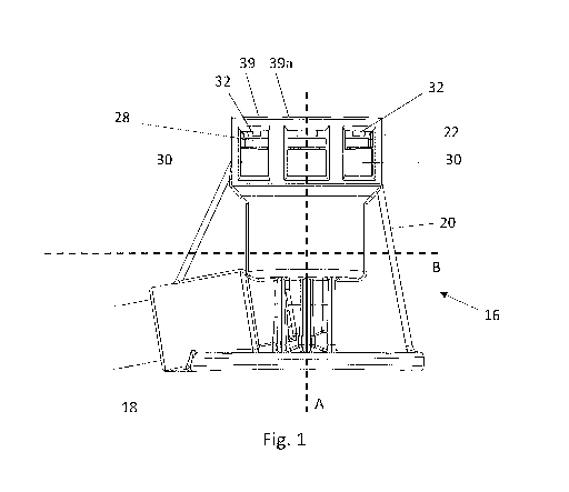
Figure 1 is a schematic side elevation of a connector in accordance with first
aspect of the
present invention;
Figure 2a is a section view of the body of the connector of Figure 1;
Figure 2b is a section view of the connector of Figure 1;
Figure 3 is a schematic representation of the connector of Figure 1 in use;
Figure 4 is a schematic top view of the body of the connector in accordance
with the first
aspect of the present invention;
Figure 5 is a front elevation of a blood purification system in accordance
with the second
aspect of the present invention;
Figure 6 is a schematic side elevation of a blood purification system in
accordance with
the second aspect of the present invention; and
Figure 7 is a section view of the system of Figure 6.
DETAILED DESCRIPTION
The connector 16 comprises a body 20, a collar 22, an annular seal 24, a grip
ring 26, and
a retaining ring 28.
The body 20 defines a fluid conduit 34. The fluid conduit 34 has a first port
38 and a
second port 36 disposed at each end of the fluid conduit 34.
The collar 22 surrounds the first port 38. The collar 22 defines an inner
surface 23 which
has a stepped profile. The stepped profile provides a surface against which
the annular
seal 24, the grip ring 26, and the retaining ring 28 are seated.
4
CA 03141686 2021-11-23
WO 2020/240151
PCT/GB2020/050989
The collar 22 further includes a series of circumferentially disposed windows
30 and a
series of circumferentially disposed protrusions 32. The protrusions 32 are
aligned with
the windows 30 such that there is one protrusion 32 for each window 30. Each
protrusions
32 further includes a ramp 33. The ramp 33 is angled towards the first port
38.
The annular seal 24, the grip ring 26, and the retaining ring 28 are each
generally annular.
The grip ring 26 includes a series of teeth 44 extending radially inwards and
towards the
first port 38. The annular seal 24 may be an o-ring, although any suitable
shape which fits
onto the inner surface 23 is possible. The retaining ring 28 is disposed on
top of the grip
ring 26 so as to secure the grip ring 26 and the annular seal 24 to the inner
surface 23 of
the collar 22. The retaining ring 28 is held in position by the protrusions
32, as will be
explained in more detail below.
A flexible tube 18 is received in the second port 36 of the fluid conduit 34.
The flexible
tube 18 may be made of PVC. The flexible tube 18 may be solvent bonded to the
second
port 36.
The fluid conduit 34 is formed of a first fluid conduit 54 and a second fluid
conduit 56. The
first fluid conduit 54 extends substantially along a vertical axis A and the
second fluid
conduit 56 extends substantially along a horizontal axis B. Hence, the second
fluid conduit
56 is disposed substantially transverse with respect to the first fluid
conduit 54.
As shown in Figure 4, the first fluid conduit 54 is arranged along a vertical
axis A, and
encircled by a tube 35. The tube 35 is arranged within the collar 22 to define
an annular
gap 40 therebetween. The collar has a pair of shims 39a extending vertically
away from
the collar 22. The shims 39a are disposed opposite to each other on a top
surface 39 of
the collar 22, and disposed circumferentially along a portion of the top
surface 39 of the
collar 22. A ridge 37 is disposed on an inside surface of the tube 35 and
extends radially
towards the vertical axis A. The ridge 37 may prevent a user from inserting a
male
connector, for instance a male luer connector, into the tube 35.
Referring to Figure 5, the top surface 39 of the connector 16 is drafted, to
facilitate easier
removal of the connector 16 from a mould following injection moulding. The
shims 39a
are disposed on lowermost areas of the drafted top surface 39. The shims 39a
stabilise
the container 12 about the vertical axis A when a fluid under variable
pressure flows from
the container 12 and through the connector 16, as will be explained in more
detail below.
5
CA 03141686 2021-11-23
WO 2020/240151
PCT/GB2020/050989
In a preferred embodiment, shown in Figure 2b, the stepped inner surface 23
includes a
first inner surface 23a, a second inner surface 23b, a third inner surface
23c, and a fourth
inner surface 23d. Each of said inner surfaces (23a to 23d) extend
circumferentially around
and along the vertical axis A. The annular gap 40 is defined between the tube
35 and the
first inner surface 23a. The second inner surface 23b provides an engaging
surface for the
annular seal 24. The third inner surface 23c provides an engaging surface for
the grip ring
26. The fourth inner surface 23d provides an engaging surface for the
retaining ring 28.
The retaining ring 28 is held between the fourth inner surface 23d and the
protrusions 32.
The inner surfaces are of varying diameter, such that the first inner surface
23a is the
smallest in diameter, and the fourth inner surface is the largest in diameter.
Referring to Figures 2a and 2b, the collar 22 also defines three seats - a
first seat 25a, a
second seat 25b, and a third seat 25c. Each said seat is disposed
perpendicularly to each
inner surface, such that each seat forms an annulus disposed circumferentially
around the
vertical axis A. Each said seat separates two neighbouring inner surfaces,
such that the
first seat 25a separates the first inner surface 23a and the second inner
surface 23b, the
second seat 25b separates the second inner surface 23b and the third inner
surface 23c,
and the third seat 25c separates the third inner surface 23c and the fourth
inner surface
23d.
The third seat 25c includes a series of flats 27 disposed circumferentially
around the
vertical axis A and between the windows 30 of the collar 22. In a preferred
embodiment,
the connector 16 comprises at least two flats 27. Each flat 27 defines a
surface for the
retainer ring 28 to sit on. The flats 27 prevent the ring 28 from rocking side
to side, causing
leakage. A combination of flats 27 and shims 39a prevents the rocking of the
connector
16, thereby significantly reducing the risk of fluid leakage from the
connector 16.
The annular seal 24 engages the second inner surface 23b and is disposed on
the first seat
25a. The grip ring 26 engages the third inner surface 23c and is disposed on
the second
seat 25b. The retaining ring 28 engages the fourth inner surface 23d and is
disposed on
the third seat 25c.
Assembly
The connector 16 is assembled as follows:
First the annular seal 24 is inserted through the collar 22 and disposed on
the first seat
25a, and such that the seal 24 engages the second inner surface 23b. Second,
the grip
ring 26 is inserted into the collar 22, such that it engages the third inner
surface 23c and
6
CA 03141686 2021-11-23
WO 2020/240151
PCT/GB2020/050989
the second seat 25b. Third, the retaining ring 28 is inserted through the
collar 22 and
disposed on the third seat 25c, and such that the retaining ring 28 engages
the fourth
inner surface 23d. The diameters of both the annular seal 24 and the grip ring
26 is less
that the collar 22 and less that the space provided between radially opposing
protrusions
32, such that the annular seal 24 and the grip ring 26 fit easily between the
protrusions
32.
The diameter of the retaining ring 28 is larger than the space provided by the
radially
opposed protrusions 32. Due to the presence of the windows 30, the protrusions
32 are
flexible and are able to resile in the radial direction. The protrusions 32
have ramps 33
which are angled towards the first port 38 of the connector 16. Therefore,
during the
insertion of the retaining ring 28, the ramps 33 are the first component which
contacts the
retaining ring. Advantageously, the ramps 33 facilitate easier insertion of
the retaining
ring 28 into the connector 16.
The flexible nature of the protrusions 32 is utilised in order to place the
retaining ring 28
in position. The retaining ring 28 is forcibly inserted past the protrusions
32, which resile
in the radial direction. Once the retaining ring 28 has passed the protrusions
32, the
protrusions elastically return to their initial position. The retaining ring
28 is thus held in
place on top of the grip ring 26 and under the protrusions 32. In this
position, the retaining
ring 28 is stacked upon the annular seal 24 and grip ring 26, and holds the
annular seal
24 and grip ring 26 securely in place.
Usage
Figure 3 shows a schematic representation of two connectors 16 as part of a
dialysate
circuit 100 of a dialysis machine. The dialysate circuit 100 includes a
disposable cartridge
200, for example the dialysate mixing and pumping cassette of WO 2010/146344
the
entire contents of which are incorporated herein by reference, or the
dialysate mixing and
pumping cassette of WO 2013/110919 the entire contents of which are
incorporated herein
by reference.
The disposable cartridge 200 is responsible for pumping and mixing dialysate
and has a
clean dialysate outlet port 202, a spent dialysis inlet port 204, a water
inlet port 206, a
water outlet port 208 and a bicarbonate solution inlet port 210. Ports 202,
204 are
fluidically connected to dialyser 102. Dialyser 102 has a blood inlet port 122
for receiving
blood from arterial blood line 124 and blood outlet port 126 for sending blood
to venous
blood line 128.
7
CA 03141686 2021-11-23
WO 2020/240151
PCT/GB2020/050989
Purified water is admitted into the cartridge 200 from a purified water supply
300 via the
water inlet port 206. The purified water passes through the cartridge 200 and
exits the
cartridge 200 at the water outlet port 208. The bicarbonate container 12 has a
purified
water inlet port 306 and a bicarbonate solution outlet port 308. Purified
water is passed
from the water outlet port 208 of the cartridge 200 to the purified water
inlet port 306 of
the bicarbonate container 12 via flexible tubing 18 and connector 16.
Similarly,
bicarbonate solution is passed from the bicarbonate solution outlet port 308
of the
bicarbonate container 12 via flexible tubing 18 and connector 16. The
bicarbonate solution
enters the cartridge 200 via bicarbonate solution inlet port 210. The flexible
tubing 18
may be made from PVC. The flexible tubing 18 may be solvent bonded to the
connectors
16.
Therefore, the connector 16 may be used to provide an irreversible fluid tight
connection
from a purified water supply (via the disposable cartridge 200) to a container
12, or to
provide an irreversible fluid tight connection from the container 12 to the
dialysis machine,
or both.
The use of connector 16 at the purified water inlet port 306 of the
bicarbonate container
12 and the use of the connector 16 at the bicarbonate solution outlet port 308
of the
bicarbonate container 12 are similar, such that only the later shall be
described in detail.
With reference to Figures 4 to 7, the blood purification system comprises the
connector 16
as set forth above, and the container 12 for storing bicarbonate powder, or
any other
suitable source of dialysate.
The container 12 has a substantially cylindrical body 14, and a stem 46
extending from at
least one end of the container 12. The body 14 defines an interior 50, where
the dialysate
powder is stored. The stem 46 has a bicarbonate solution outlet port 308
disposed at the
free end of the stem 46. The stem 46 further includes a chamfered edge 52 on
the wall of
the stem 46 that faces away from the port 308.
The stem 46 is received in the annular gap 40 of the connector 16. The port
308 of the
stem 46 partially receives the first fluid conduit 54 thus fluidly connecting
the first fluid
conduit 54 to the container 12. The stem 46 receives the entirety of the port
38 of
connector 16.
8
CA 03141686 2021-11-23
WO 2020/240151
PCT/GB2020/050989
When inserted into the connector 16, the stem 46 of the container 12 engages
the grip
ring 26 and the annular seal 24.
The annular seal 24 provides a fluid tight connection between the container 12
and the
connector 16. On the other hand, the grip ring 26 provides an irreversible
connection
between the container 12 and the connector 16.
The annular seal 24 engages the second inner surface 23b and the first seat
25a of the
collar 22, as well as the wall of the stem 46 facing away from the port 48. As
such, the
system can remain pressurized upon passing fluid from the interior 50 of the
container 12
into the fluid conduit 34, or vice versa.
Upon inserting the stem 36 into the annular gap 40 between the fluid conduit
34 and the
collar 22, the teeth 44 bend further towards the annular gap, thus exerting a
reaction
.. force on the wall of stem 46 facing away from the port 48.
During the insertion of the container 12 into the connector 16, or vice versa,
the chamfered
edge 52 is the first element of the container 12 engages the grip ring 26.
In use, the operator of the dialysis machine can only insert the container 12
into the
annular gap 40 in the direction in which the teeth 44 of the ring 26 are
pointing. Once the
teeth 44 of the grip ring 26 engage the stem 46, the connector 16 firmly grips
the container
12, and both components become irreversibly connected.
The retaining ring 28 reacts the forces due to the spring back of the teeth 44
of the grip
ring 26, thus the retaining ring 28 is constrained axially by the protrusions
32. This
constraint further ensures that the container 12 cannot be removed from the
connector
16.
In use, upon completing the treatment, the container 12 and the connector 16
are
disposed of as a single assembly.
9
CA 03141686 2021-11-23
WO 2020/240151
PCT/GB2020/050989
List of Reference Numerals
- container 12
- cylindrical body 14
- connector 16
- flexible tube 18
- body 20
- collar 22
- inner surface 23
- stepped inner surface 23
- annular seal 24
- grip ring 26
- flats 27
- reatining ring 28
- surface 28
- windows 30
- protrusions 32
- ramp 33
- fluid conduit 34
- tube 35
- second port 36
- ridge 37
- first port 38
- top surface 39
- annular gap 40
- series of teeth 44
- stem 46
- stem 46
- port 48
- interior 50
- chamfered edge 52
- first fluid conduit 54
- second fluid conduit 56
- dialysate circuit 100
- dialyser 102
- blood inlet port 122
- arterial blood line 124
- blood outlet port 126
- blood line 128
- disposable cartridge 200
- clean dialysate outlet port 202
- spent dialysis inlet port 204
- water inlet port 206
- water outlet port 208
- bicarbonate solution inlet port 210
- purified water supply 300
- water inlet port 306
- bicarbonate solution outlet port
308
- first inner surface 23a
- inner surfaces 23a, 23b, 23c, 23d
- second inner surface 23b
- third inner surface 23c
- fourth inner surface 23d
- first seat 25a
- second seat 25b
- third seat 25c
- pair of shims 39a
CA 03141686 2021-11-23
WO 2020/240151
PCT/GB2020/050989
- shims 39a
- vertical axis A
- horizontal axis B
11