Note : Les descriptions sont présentées dans la langue officielle dans laquelle elles ont été soumises.
CA 03142273 2021-11-29
WO 2020/247543 PCT/US2020/035991
REAL TIME CARDIOPULMONARY RESUSCITATION (CPR) FEEDBACK
WITH INSTRUCTIONS APPARATUS AND METHOD OF USE
CROSS REFERENCE TO RELATED APPLICATIONS
[0000] This application claims priority to and the benefit of U.S.
Provisional
Patent Application No. 62/972,574 filed February 10, 2020, U.S. Provisional
Patent
Application No. 62/972,544 also filed on February 10, 2020, and U.S.
Provisional Patent
Application No. 62/856,544 filed June 3, 2019, the entire contents of each are
incorporated by reference herein.
FIELD OF THE INVENTION
[0001] This invention relates to the field of medical devices. More
specifically, it
relates to coaching and assistive devices used by first responders, medical
professionals, and other rescuers while performing cardiopulmonary
resuscitation
(CPR) or learning to do so.
BACKGROUND OF THE INVENTION
[0002] Chest compressions are an important part or CPR where the rescuer
or
first responder places one hand on top of the other and pushes on the victim's
chest,
ideally at a rate and force in accordance with medical guidelines, e.g., the
American
Heart Association (AHA) guidelines (Virani SS etal., (2020), Circulation,
141(9):e139-
56). The goal of these compressions is to maintain blood flow and oxygen
supply to the
victim's body when their heart is beating irregularly or not at all. It is
important for the
rescuer or first responder to apply compressions with enough force and
frequency to
create adequate blood circulation for the victim. When done correctly, CRP can
increase the likelihood of the victim's survival.
1
CA 03142273 2021-11-29
WO 2020/247543 PCT/US2020/035991
[0003] Administering CPR correctly, however, can be difficult. Rescuers
or first
responders or first responders often have to perform chest compressions in
stressful
situations and for extended periods of time. The rescuer or first responder
can become
fatigued or have their focus impaired. Under these conditions, it is very
difficult to
effectively estimate the force that needs to be applied to the victim's chest
or the
frequency of compressions required to give the victim proper blood
circulation. Studies
have demonstrated that even trained professionals often misjudge these two
parameters while performing CPR and, as a result, provide less than adequate
CPR for
the victim, hurting their odds of survival.
[0004] For this reason, there is a need for a practical device that can
measure
various parameters of the rescuer's or first responder's CPR performance and
dive
feedback in an effective way, in real time. This would be useful in real
medical
emergencies or for practicing CPR in a training setting. Devices have been
proposed to
help with this. One instance of this is U.S. Pat. No. 5,496,257 (Kelley) that
discloses a
device placed on the victim's chest and uses a pressure sensor to measure
compression forces and timing. The device has a visual and audio feedback
system
built into the same housing that holds the pressure sensors. This could make
the device
difficult to use in certain conditions such as the back of a moving ambulance
because
the device would not be secured in place. The device would be free to move
anytime
the rescuer or first responder is not actively holding it in place, for
example, while they
are delivering rescue breaths between compressions. Additionally, it is
standard to be
trained to perform CPR wearing only light gloves so adding a bulky housing
between
2
CA 03142273 2021-11-29
WO 2020/247543 PCT/US2020/035991
the rescuer's or first responder's hands and the patient's chest could be
unfamiliar or
uncomfortable for the rescuer or first responder.
[0005] Another instance of a CPR assistive device is described in U.S.
Pat. No.
9,028,259 (Centen etal.) that discloses a wearable device that goes on one of
the
rescuer's or first responder's hands to measure CPR parameters. To display
visual
feedback to the user, the patent describes transmitting the data "to a
separate
computing device, such as a personal computer or a portable wireless device
for
display." This is not desirable because the separate computing device would
draw the
rescuer's or first responder's attention away from the victim. Even if the
separate
device is moved to be proximate to the victim and site of compression, it
could add
unneeded complexity to the system or be unstable if used, for example, in a
moving
ambulance. The patent also describes an alternative apparatus where feedback
is
displayed on the back of the hand wearing the glove. This would not work well
because
the rescuer or first responder needs to place one hand over the other while
performing
CPR. The back of the hand with the sensors and display would be obstructed by
the
other hand.
[0006] Another instance of a CPR assistive device is described in U.S.
Pat. No.
8,147,433 (Halperin etal.) that discloses a CPR-assistive device that uses an
accelerometer in a location fixed to the patient's chest to measure
compression depth.
It determines depth of compression independently of any reference data. This
system
is not desirable due to the absence of reference data indicating movements of
the
patient's body not caused by chest compressions. If the device were to be used
in a
moving vehicle like an ambulance, the device might not be able to discern
movements
3
CA 03142273 2021-11-29
WO 2020/247543 PCT/US2020/035991
of the vehicle from movement caused by chest compression. Taking into
consideration
possible data filtering methods, noise still impacts the accuracy of the
device. Using an
additional reference device such as an accelerometer would allow the device's
processor to more effectively differentiate chest compression movement from
other
movements of the victim's body even when the movements have the same frequency
and share other characteristics.
[0007] Another instance of a CPR assistive device is described in U.S.
Pat. No.
9,585,603 (Centen). R discloses a CPR assistive device that uses "a field
generator, a
field detector, and a processor" to determine the depth of chest compressions
during
CPR. The field generator acts as a reference to move with the patient's body
so the field
detector will only measure motion about this reference generator. This would
be an
adequate way to differentiate chest compression movements from movements of
the
patient's body. This is not desirable, however, because any type of electric
or magnetic
field used in this way could interfere with a patient's pacemaker or other
implanted
metal or electronic devices.
BRIEF SUMMARY OF THE INVENTION
[0008] The present invention is a medical device to assist a rescuer or a
first
responders or first responders in performing CPR more effectively by giving
real time
feedback on the quality of compressions and/or how the compressions should be
corrected. The device can also be used in the same way while a student (person
learning or practicing CPR) is practicing CPR chest compressions. The device
will
include one or more sensors to detect one or more parameters relating to the
quality of
the rescuer's or first responder's CPR chest compressions. These sensors can
be
4
CA 03142273 2021-11-29
WO 2020/247543 PCT/US2020/035991
positioned between the rescuer's or first responder's lower hand and the
victim's chest,
on the back of the rescuer's or first responder's upper hand, or at any other
position
adequate for the sensor's detection.
[0009] The device will also include a display or other feedback system.
This
system will provide instructions pertaining to CPR. This system will also be
used to
provide visual CPR feedback or queues for performing better CPR. The device
may
also include auditory and/or tactile outputs to go along with or replace the
visual display
system. Using the described device and method will allow a rescuer or first
responder to
provide the best possible care when performing CPR, giving the optimal
survival
probability to the victim.
BRIEF DESCRIPTION OF THE FIGURES
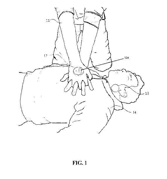
[0010] FIG 1 is an illustration depicting a rescuer or first responder 11
administering CPR to a victim 14.
[0011] HG 2 is a schematic drawing of from the perspective of the top of
the
main device 12 as shown in FIG. 1.
[0012] FIG 3 illustrates an exploded view of the main device 12 as shown
in
FIG. 1.
[0013] FIG 4 illustrates an exploded view of the adhesive component.
[0014] FIG 5 shows an exploded view of the reference device 13.
[0015] FIG 6 is a flow chart describing the data processing pathway.
[0016] FIG 7 illustrates the container or hub 71 that is used as a
central location
to store the device.
CA 03142273 2021-11-29
WO 2020/247543 PCT/US2020/035991
[0017] FIG. 8 depicts the rescuer or first responder 11 administering CPR
to the
victim 14.
[0018] AG. 9 depicts the hardware components of the device.
[0019] AG. 10 depicts the process by which the system could be used to
provide
instructions before CPR and feedback during CPR in order to guide the user in
the
proper administration of CPR.
[0020] FIG 11 depicts the process by which the algorithm processes and
analyzes the data from the accelerometer, compares it to a standard and
provides
feedback to the rescuer or first responder. This process repeats as long as
the rescuer
or first responder is performing CPR.
[0021] FIG 12 depicts a student 11 practicing CPR on a mannequin 13. An
embodiment of the CPR assistive device 12 described herein is attached to the
back of
the student's top hand 11 while practicing CPR. In some preferred embodiments,
the
CPR assistive device can be a smart phone 11 which includes appropriate
functions
described herein.
[0022] FIG 13 depicts the process by which the system is used in order to
train or
practice the proper administration of CPR.
[0023] FIG 14 demonstrates how a camera could be used in order to train
or
practice the proper administration of CPR.
[0024] AG 15 depicts the process by which a mannequin or dummy would be
sent by an instructor and received by a student in order to train or practice
the proper
administration of CPR.
6
CA 03142273 2021-11-29
WO 2020/247543 PCT/US2020/035991
[0025] FIG 16 depicts the process by which use of a generated
authentication
key unlocks and locks the software.
[0026] FIG 17 demonstrates the process through which the software is
locked
and unlocked with the use of a static authentication key.
DETAILED DESCRIPTION OF THE INVENTION
[0027] Disclosed herein is a novel device and method to assist rescuers
or first
responders in the performance of CPR or to assist a student in learning or
practicing
CPR.
Apparatus
[0028] FIG. 1 shows an embodiment of the invention which includes two
parts: a
main device 12 and a reference device 13 (collectively referred to hereinafter
as "the
device"). The main device 21 is comprised of a housing made from a
semiflexible
polymer selected from the group, including, but not limited to polyvinyl
chloride (PVC),
polypropylene (PP), polyethylene (PE), polystyrene (PS) as well as nylon,
polyethylene
terephthalate (PET), polyimide (PA), polycarbonate (PC), acrylonitrile
butadiene (ABS),
polyurethane (PU) and polyetheretherketone (PEEK) (BMP Medical, Sterling, MA)
with
a non-conductive adhesive (or medically-approved adhesive pads that may be
replaced
and discarded after use) (Panacol-USA, Torrington, CT) on one side (not shown)
and a
user feedback display 12A on the opposite side. When preparing to perform CPR,
the
main device 12 will be adhered to the back of the rescuer's or first
responder's hand 11
or glove (not shown) or held by the rescuer or first responder. As shown in
FIG. 1, it
can be adhered (disposable adherence pad not shown) to the back of the hand 11
or
glove that will be on top when the rescuer's or first responder's hands 11 are
placed in
7
CA 03142273 2021-11-29
WO 2020/247543 PCT/US2020/035991
position to perform CPR. The device 12 will be able to use data from an
accelerometer,
and possibly other sensors, to measure the depth of displacement of the
rescuer's or
first responder's hands as they perform CPR chest compressions. Based on the
depth
of displacement, the device 12 will give visual or other feedback, as shown in
FIG. 2
(the top view of the main device 21), to the rescuer or first responder 11 so
they can
apply more or less force with each compression; as necessary. The rescuer or
first
responder 11 would be able to see the compression depth displayed on a
continuous
monitor 23 that has marks, i.e., "--", "NI" or "+" indicating whether the
depth was too little,
adequate or too much. There would also be a frequency indicator 22 that would
consist
of either a vibration motor, blinking diode; or speaker 25 that would pulse at
the correct
compression pace.
[0029] Each main device 12, as shown in FIGs 3 and 4, comprises a housing
33
containing a power source 44 such as a CR1620 (Panasonic , Kadorna-shi, Osaka,
JP)
or other watch batteries (Energizer Holdings, St. Louis, MO); an
accelerometer 39 such
as the LIS3DH triple-axis accelerometer (Adafruit Industries LLC, New York,
NY), a
processor 38 such as an ATMEGA32U4-AU (AVR AVR ATmega Microcontroller IC 8-
Bit 16MHz 32KB (16K x 16) FLASH 44-TOFP (10x10)(Microchip Technology, Inc.,
Chandler; AZ), and a feedback display 35 such as a Nokia 5110/3310 monochrome
LCD (Nokia , Espoo, Fl). It may also include one or more vibration motors 36
(Adafruit
Industries LLC, New York, NY) and/or a wired or wireless data transmission
system 34.
There is a non-conductive adhesive layer 41 (Panacol-USA, Torrington, CT)
attached to
housing 42 for the battery 44. The battery 44 is connected to conductive
strips 43 and
47 that carry current to snaps 46 and 48 that are embedded into the top layer
of the
8
CA 03142273 2021-11-29
WO 2020/247543 PCT/US2020/035991
device 45. A non-conductive adhesive pad 31 comprising snaps 32 and 37
embedded
in the non-conductive adhesive pad 31 connect the electronics to the battery
44. The
device has a top cover 40 that contains a screen 35 and a vibration motor,
blinking
diode or speaker 36.
[0030] The main device 12 is paired with a reference device 13 shown in
FIG 1.
As depicted, the main device 12 is adhered to the back of the rescuer's or
first
responder's 11 top hand while performing CPR. The reference device 13 is
adhered to
the victim's 14 neck. The reference device 13 is also comprised of a housing
made
from a semiflexible polymer selected from the group, including, but not
limited to
polyvinyl chloride (PVC), polypropylene (PP), polyethylene (PE), polystyrene
(PS) as
well as nylon, polyethylene terephthalate (PET), polyimide (PA), polycarbonate
(PC),
acrylonitrile butadiene (ABS), polyurethane (PU) and polyetheretherketone
(PEEK)
(BMP Medical, Sterling, MA) with a non-conductive adhesive (or medically-
approved
adhesive pad that may be replaced and discarded after use) (Panacol-USA,
Torrington,
CT) on one side (not shown). As the rescuer or first responder 11 is preparing
to
perform CPR on the victim 14, the reference device 13 is affixed to the side
of the
victim's 14 neck, the victim's 14 vertebro-distal rib near the 6th intercostal
space, the
victim's 14 back, or on another stable part of the victim's 14 body using the
non-
conductive adhesive (or medically-approved adhesive pad that may be replaced
and
discarded after use) (Panacol-USA, Torrington, CT). The reference device 13
measures movement of the victim 14 so it should be placed on part of the
victim 14 that
moves with the torso of the victim 14, but independently of the chest
compressions
administered to the victim 14.
9
CA 03142273 2021-11-29
WO 2020/247543 PCT/US2020/035991
[0031] The reference device 13, as shown in FIGs 4 and 5 includes an non-
conductive adhesive pad 51 (Panacol-USA, Torrington, CT), power source such as
a
CR1620 (Panasonic , Kadoma-shi, Osaka, JP) or other watch batteries (Energizer
Holdings, St. Louis, MO), an accelerometer 57 such as the LIS3DH triple-axis
accelerometer (Adafruit Industries LLC, New York, NY), a processor 56 such as
an
ATMEGA32U4-AU (AVR AVR ATmega Microcontroller IC 8-Bit 16MHz 32KB (16K x
16) FLASH 44-TQFP (10x1 0)(Microchip Technology, Inc., Chandler, AZ, and a
wired or
wireless data transmission system. The reference device 13 includes a layer
that
connects the adhesive pad 51 using snaps 52 and 55 that connect the
electronics to the
battery (not shown). There is also housing 53 in which the electronics would
be
embedded. The device also includes a top cover 58.
[0032] The device will operate as shown in FIG 6 that depicts how data
from both
the reference device 13 and main device 12 is transmitted to the main device
12.
When the main device 12 is turned on, the accelerometer 39 in the main device
12 and
the accelerometer 57 in the reference device 13 will begin collecting data.
The data
from the main device's accelerometer 39 will be transmitted to the processor
38 in the
main device 12. Simultaneously, the data from the reference device's 13
accelerometer
57 will be sent to the reference device's 13 processor 56. The data from the
reference
device's 13 processor 56 will then be transmitted (vvirelessly or with a wire)
to the
processor 38 in the main device 12. The processor 38 in the main device 12
will
convert both acceleration data sets to velocity and displacement data. The
processor 38
in the main device 12 will then determine if the rescuer or first responder 11
is
performing compressions and check if the displacement of the rescuer's or
first
CA 03142273 2021-11-29
WO 2020/247543 PCT/US2020/035991
responder's 11 chest compressions are above or below a given set of two
thresholds. If
the displacement is below both thresholds, the processor 38 will activate a
visual
display 35 in the main device 12 indicating to the rescuer or first responder
11 to use
more force. If the displacement falls between the thresholds, the processor 38
will
activate the visual display 35 in the main device 12 indicating that the force
used is
adequate. If the displacement is greater than both thresholds, the processor
38 will
activate visual display 35 in the main device 12 indicating to the rescuer or
first
responder to use less force.
[0033] A preferred embodiment of the device will allow the non-conductive
adhesives 41 and 51 and/or batteries 44 powering the main device 12 and
reference
device 13 to be disposable and replaceable. This disposable part of the
device, as
shown in FIG. 8 that depicts a second embodiment of the CPR assistive device
12
described herein that is attached to the back of the rescuer's or first
responder's top
hand 11 while performing CPR, could be used with the main device 12 or the
reference
device 13. This way after each use the partly drained batteries can be
replaced with
new batteries and/or the single use non-conductive adhesive will be replaced
with a
new non-conductive adhesive which will be ready for the device's next use.
Meanwhile,
all the other electronic components in the device will be made of or housed in
sterilizable materials so they can be sterilized and reused. The disposable
part of the
device will attach to the reusable part in a non-symmetrical manner so it
would be
impossible to reverse the polarity of the batteries in the disposable part
with respect to
the electrical components in the reusable part. Alternatively, the reusable
part of the
device could be designed and wired so it can operate independently of battery
polarity.
11
CA 03142273 2021-11-29
WO 2020/247543 PCT/US2020/035991
[0034] In an alternative embodiment, the main device 12 could also be
made to
give feedback indicating if the rescuer or first responder 11 is allowing the
chest of the
patient 14 to recoil properly. This could be done by comparing the main
device's 12
accelerometer 39 data corresponding to the downstroke of the compression with
the
data corresponding to the upward stroke. If the rescuer or first responder 11
pushed
down farther than they pulled up, then the device would indicate that there is
inadequate
chest recoil via the feedback interface.
[0035] In an alternative embodiment, the main device 12 could operate
without
the reference device 13 to reduce the cost of the device. Instead of using the
reference
device 13 to monitor the motion of the patient's body 14, the main device 12
assumes
that the patient's body 14 is stable or use frequency analysis to
differentiate chest
compression movement from other movements. This would be useful in situations
like
a hospital setting where the patient is simply laying on a hospital bed, but
it would be
less desirable for situations where CPR is administered in a moving vehicle
like an
ambulance.
[0036] In another alternative embodiment, the thresholds discussed in
Para. [0032] above, could be set by the rescuer or first responder 11 or
otherwise
modified before, during, or after performing CPR based on the size, age,
weight, or
build of the patient 14 or based on other parameters.
[0037] In another alternative embodiment, the main device 12 or the
reference
device 13 could be equipped with additional sensors to gather data. This data
could be
transmitted to the main device 13 processor 38 that would be programmed to
activate or
change the user feedback display 35 to provide additional feedback to the
rescuer or
12
CA 03142273 2021-11-29
WO 2020/247543 PCT/US2020/035991
first responder 11. The additional data gathered by the main device 12 or the
reference
device 13 could also be transmitted and/or saved to an external computer
system or
display (not shown). It could further be compared to other data to assess the
patient's
health.
[0038] Another alternate embodiment includes an additional non-conductive
adhesive component with a separate battery, microprocessor, and wireless
transmitter
placed on the front or back of the rescuer's or first responder's 11 bottom
hand. This
could also take the form of a device placed on the victim's 14 chest. It would
include
accelerometers and/or pressure sensors (similar to Minarni K et al., (2016),
Resuscitation, 99:e11-12) to gather more data on the quality of CPR chest
compressions being administered. This could improve the accuracy of the device
because by providing additional data.
[0039] In another alternative embodiment, the battery 44 on the main
device 12
or the reference device 13 could be made to be recharged instead of being
replaced.
The main device 12 and/or the reference device 13 would also include a
charging port
or wireless charging capabilities.
[0040] Other alternative embodiments involve the same electrical
components
present in the main device 12 housed in different ways that can operate
independently
of a reference device 13. The main device 12, according to this embodiment, is
a glove
worn on the rescuer's or first responder's 11 top hand with the visual display
35 on the
back of the same hand. The device could also attach to the rescuer's or first
responder's 11 top hand with a hook and loop fastening means such as a strap
(commercially sold under the tradename Velcro (Velcro BVBA, Deinze, BE) so the
13
CA 03142273 2021-11-29
WO 2020/247543 PCT/US2020/035991
visual feedback display would be on the back of the hand. Another embodiment
of the
device could consist of a rigid plastic part held below the rescuer's or first
responder's
11 bottom hand while in use. It would have an attached part extending around
the
rescuer's or first responder's 11 hands to give a visual feedback display
above the
rescuer's or first responder's 11 top hand. All of these alternative device
housings
would still take data and give feedback in the same way as discussed above.
[0041] In another alternate embodiment of the invention, the device could
be
modified to have two or more main devices connected to a common reference.
This
would allow multiple rescuers or first responders or first responders to take
turns
administering chest compressions, alternating when one rescuer or first
responder gets
fatigued.
[0042] In a further embodiment, the reference device 13 could be designed
to be
permanently or temporarily attached to a hospital bed, gurney or stretcher.
This
embodiment would not require that the device be attached directly to the
patient's body.
This embodiment of the claimed invention would be used in situations where the
patient
is injured or has a wound in the areas where the device is to be adhered.
[0043] In another embodiment, the reference device 13 is designed to be
attached to a hub or housing/storage container 71 used as a central location
to store the
other devices (and replaceable pads used to secure the device to the patient
(14)) as
depicted in FIG. 7. The reference device (13) 72 would be stored on the
outside of the
hub 71 and the main device 12 (not shown) or devices would be dispensed from a
slot
or opening 73 found in the wall of the hub or housing/storage container 71
allowing for
the main device 12 (not shown) or devices and reference device 72 or devices
to be
14
CA 03142273 2021-11-29
WO 2020/247543 PCT/US2020/035991
stored in a compact container so they can be readily available for use. This
hub or
housing/storage container 71 could also have capabilities to recharge one or
more main
or reference devices with a wire or wirelessly. This hub or housing/storage
container 71
could be included on or attached to a hospital crash cart or the inside of an
ambulance.
In some situations, the reference device 72 is left on the hub or
housing/storage
container 71 instead of attaching to the patient to make use of the invention
more
streamline.
[0044] In another alternative embodiment, the reference device 13 could
be
designed to record other biometrics or data points from the patient. This data
could be
sent to the main device 12 or an external device to be saved or used in other
ways
while assessing or monitoring a patient's health.
[0045] In yet a further embodiment, the main device 12 could be altered
to attach
to a rescuer's or first responder's 11 fingers or thumb to track depth of CPR
chest
compressions administered to infants.
[0046] In another embodiment, the main device 12 could also be designed
to
provide feedback to the rescuer or first responder on the frequency of chest
compressions administered by measuring the frequency of the chest compressions
then
providing visual, auditory, or tactile feedback to the rescuer or first
responder depending
on how their frequency compares to a given target frequency. Alternatively,
the main
device 12 could simply act as a metronome, wherein the rescuer or first
responder
would match their compressions with the beat of the metronome. The metronome
could
be made with a speaker, making a sound for every beat administered, or with a
CA 03142273 2021-11-29
WO 2020/247543 PCT/US2020/035991
vibration motor that would vibrate for every beat, or alternatively, a small
light that blinks
for every beat of the metronome.
[0047] In another alternative embodiment, the device could be programmed
to
suppress output when the rescuer or first responder is not performing chest
compressions so as not to be distracting if the rescuer or first responder is
performing
rescue breaths or resting while switching off with another rescuer or first
responder.
[0048] In a further embodiment, the device would only provide feedback
when the
rescuer or first responder deviates from the pre-programmed chest compression
target.
If the rescuer or first responder is performing CPR that meets the given
guidelines and
targets, the device does not provide any distracting information.
[0049] In an alternative embodiment, the device could be modified to be
more
suitable to be used in a classroom setting for training purposes. The adhesive
on the
main device would be removed and instead the main device would simply strap to
the
back of the user's hand, be held, or attached in another way so that the
device may be
re-used without replacing any parts. In this embodiment, the reference device
13 could
be omitted because it is rendered unnecessary for most training scenarios.
[0050] In another alternative embodiment, the device could be made to
sync with
an automated external defibrillator (AED)(ZOLL Medical Corporation,
Chelsmford, MA)
that is being used on the same patient. The AED, main device 12, and reference
device
13 would be designed to transmit data back and forth. The AED pads (AED Brands
,
Kennesaw, GA) that adhere to the patient's chest could also act as reference
accelerometers.
16
CA 03142273 2021-11-29
WO 2020/247543 PCT/US2020/035991
[0051] 1 n another alternative embodiment, the processor 38 on the main
device
12 could be programmed to filter the accelerometer 39 data removing the
component of
the motion that is not directed into the patient's 14 chest. Data from a
gyroscope such
as the ADXRS290 gyroscope (Analog Devices, Inc., Norwood, MA) could be used in
this filtering operation to better determine the angle of motion.
[0052] In a different embodiment, the device could be made with a visual
feedback interface that is designed to be easily understood by colorblind
rescuers or
first responders or first responders by avoiding using combinations red,
green, and
yellow together in the same interface. Instead, it could use blue and orange
or other
sets of colors with high value difference.
[0053] In a particular embodiment, either the main device 12 or the
reference
device 13 could be designed to include a temperature sensor (TE Connectivity,
Tyco
International Services GmbH, Schaffhausen, CH) to analyze, save, or transmit
body
temperature data.
[0054] In certain embodiments, the main device 12 could be designed to
include
an additional display indicating the time that has elapsed since the user
began
performing CPR helping the rescuer or first responder know if they are
approaching or
have exceeded a given CPR time limit.
[0055] In alternative embodiments, the device could be designed to
display data
indicating a history of chest compressions in addition to the real time depth
data making
it easier for the rescuer or first responder to read and understand than real
time
feedback that is rapidly changing.
17
CA 03142273 2021-11-29
WO 2020/247543 PCT/US2020/035991
[0056] In other embodiments, the main device's 12 user feedback could be
paired with another device gathering and/or processing chest compression or
other data
which could be displayed on the back of the rescuer's or first responder's
hand.
[0057] In other examples, the user interface display 35 on the main
device 12 can
be designed to give real time feedback about the depth of the compressions
throughout
the entirety of each stroke. This could be displayed as a continuous depth
meter as
shown in FIG. 2. The meter would indicate the point when the chest has been
fully
compressed, the point when the chest has fully recoiled, and a continuum of
points
between these positions.
[0058] Another preferred embodiment of the hardware device used in this
invention is the Google TM Pixel 3a (GoogleTM LLC, Mountain View, CA) as set
discussed at https://store.doodle.com/us/product/pixel 3a specs downloaded
from the
internet on June 3, 2020. Other srnartphones, smart watches, wearable devices,
or
other electronic devices with these components may still be used just as
effectively.
[0059] In a preferred embodiment, the invention of FIG. 9, depicts the
hardware
components of the device including a housing 21 containing electronics like an
on
switch 22, a battery 23, one or more movement or distance sensor, such as an
accelerometer 24, one or more speakers 25 or a gyroscope 26 such as the
ADXRS290
gyroscope (Analog Devices, Inc., Norwood, MA), a processor 27, one or more
vibration
motors 28, and one or more internal memory units 29. The device also includes
a visual
display 30 which is attached to the housing and can provide visual
instructions or CPR
feedback. Preferably, an accelerometer 24, such as the one included in Google
TM Pixel
18
CA 03142273 2021-11-29
WO 2020/247543 PCT/US2020/035991
3a (GoogleTM LLC, Mountain View, CA) and a gyroscope 26 also found in the
Google TM Pixel 3a'-') (Google T" LLC, Mountain View, CA), is used.
[0060] FIG. 9 also depicts the movement sensors in the housing 21 that
also
contains one or more memory units 29 such as a 64 gigabyte drive memory unit
included in Google TM Pixel 3a (Google TM LLC, Mountain View, CA). The
housing 21
may also contain one or more processors 27, such as a Qualcomm Snapdragon T"
670 (Qualcomm Technologies, Inc., San Diego, CA) included in the GoogleT"
Pixel 3a
(GoogleTM LLC, Mountain View, CA).
[0061] The same housing depicted in FIG. 9 that holds the sensors,
memory, and
processing hardware also houses one or more actuators for conveying
information,
feedback, and/or instructions to the user. In a preferred embodiment, the
housing 20
would hold one or more speaker 25, such as stereo speakers, as included in the
Google TM Pixel 3a12;} (Goodie TM LLC, Mountain View, CA) as well as a visual
display 30,
such as a 5.6 inch screen which is included in the Google T" Pixel 3a (Google
TM LLC,
Mountain View, CA). This embodiment may further comprise haptic feedback
capabilities, such as the vibration motors 28 included in the Google TM Pixel
3a
(GoogleTm LLC, Mountain View, CA).
[0062] This embodiment of the invention shown in FIG. 9 is powered by a
battery
23 that is also contained in the same housing 21. Preferably, a 3000 milliamp
hour
battery (Duracell Inc., Betherl, CT) would be used, as included in the Google
Tm Pixel
3a (Google TM LLC, Mountain View, CA). The housing 21 also includes a button
22 to
turn the device on and off. Preferably, a power button similar to the power
button found
in the Google TM Pixel 3a (GoogleTM LLC, Mountain View, CA). would be used.
19
CA 03142273 2021-11-29
WO 2020/247543 PCT/US2020/035991
Electrical connections would also be included to interface all the described
components
to the battery and processor.
[0063] The device's processor 38 may be programmed to use the
accelerometer
39 to take measurements of the patient's 14 chest movement and/or the
rescuer's or
first responder's 11 hand movements as a rescuer or first responder 11 is
performing
CPR; transferring the data to and stored in the memory unit 29, then processed
by the
processor 38 using an algorithm to convert the accelerometer data into
compression
depth data. This depth data will also be transferred to and stored on the
memory unit
29.
[0064] The algorithm of FIG. 11 shows that the conversion accelerometer
data to
compression depth data requires first subtracting the component of the signal
that
corresponds to the gravitational field felt by the device. The algorithm would
then take
the remaining component and filter out any noise using a high-pass filter
(Maxxcom,
Inc., Fair Oaks, CA) or any other method known by those skilled in the art.
The signal
would then be integrated with respect to time twice. Transient components of
the signal
may need to be emphasized between integrations and or after both integrations.
This
will yield a result corresponding to chest compression depth. There are
obviously a
great many alternative algorithms that could be used to get to the same
result. The
described algorithm is preferred.
[0065] The processor 38 will then compare the compression depth data to a
relevant standard on compression depth such as the standard set by the
American
Heart Association (American Heart Association , Inc., Dallas, TX). If the
rescuer's or
first responder's 11 compression depth is lower than the standard, the device
will use
CA 03142273 2021-11-29
WO 2020/247543
PCT/US2020/035991
one or more of the actuators to indicate to the rescuer or first responder 11
that they
need to push deeper into the chest. If the rescuer's or first responder's 11
compression
depth meets the standard, the device will use one or more of the actuators to
indicate to
the rescuer or first responder 11 that they reached the appropriate
compression depth.
If the rescuer's or first responder's 11 compression depth is greater than the
standard,
the device will use one or more of the actuators to indicate to the rescuer or
first
responder 11 that they should push less deep into the chest. In a preferred
embodiment, when the device is indicating chest compression depth
recommendations
to the rescuer or first responder 11, it would display this recommendation on
the visual
display unit 35 in the form of a diagram and/or text. It could also use the
speakers 25 to
dive auditory instructions on compression depth. Furthermore, haptics could be
used to
briefly activate the vibration motors 28 when the optimal chest compression
depth is
reached. Any information that is output auditorily, visually, or using haptics
could also
be stored in the memory unit 29 to be reviewed later by the rescuer or first
responder or
a medical professional.
[0066] The
device may further comprise additional sensors such as a camera,
magnetometer, button, touch screen or other sensors. The device may also use
the
accelerometer 39 and/or these additional sensors to measure additional CPR-
related
parameters such as chest compression rate, chest recoil, elapsed time, and
more.
These parameters may be stored. Feedback on these parameters may be given to
the
rescuer or first responder as well. These parameters may also be transmitted
to
another nearby device or a remote location where the information can be stored
and/or
reviewed by a medical professional, trained professional, or an additional
algorithm.
21
CA 03142273 2021-11-29
WO 2020/247543 PCT/US2020/035991
The professional or algorithm may also send instructions or information back
to the
rescuer or first responder as a response to the received data.
[0067] in the preferred embodiment, the device giving CPR feedback would
also
comprise wireless connectivity capabilities including sending and receiving
data and
other files such as found in the Goodie TM Pixel 3a (Google TM LLC, Mountain
View, CA)
or similar devices known by those skilled in the art. This device could be
held by the
rescuer or first responder, attached to their hand or wrist or otherwise
positioned to
move with the rescuer's or first responder's hands or the patient's chest
while
performing CPR. The device would use the built in accelerometer 39 and
gyroscope 26
to measure the acceleration of chest compressions. This can be used to
determine
chest compression depth as described. Chest compression rate may also be
measured
using this data. This information would be displayed on a screen, such as the
5.6 inch
screen employed by the Google TM Pixel 3a (GoogleTM LLC, Mountain View, CA),
for
the rescuer or first responder to see. Auditory and tactile feedback could
also be given
using the device's built in hardware. This embodiment is depicted in FIG. 8.
[0068] A further embodiment of this invention may additionally be
comprised to
communicate or display instructional information or directions that are
relevant for
performing CPR. These instructions would be displayed before CPR feedback is
given
and may be comprised of text and/or diagrams. The instructions may include,
but are
not limited to, the following steps: 1). checking if the patient is
responsive; 2) checking if
the patient is breathing; 3). Ensuring that the patient is on a stable, hard
surface; 4).
positioning the feedback device in a certain way; 5). positioning the
rescuer's or first
responder's hands in a certain way; and 6). commencing compressions of the
patient's
22
CA 03142273 2021-11-29
WO 2020/247543 PCT/US2020/035991
chest. The rescuer or first responder could have the option to skip
instructions so they
can read some, all, or none of the instructions depending on their training
level and
familiarity with CPR and related procedures. One way in which this could be
achieved
would be to have a setting for professional rescuers or first responders or
first
responders, who may not need as much guidance, and another for non-
professional
rescuers or first responders or first responders, who may require more
guidance. The
setting for professional rescuers or first responders or first responders
could also make
the system display additional CPR relating information and/or feedback such as
chest
recoil or elapsed time. The feedback and display could further be customized
using
other settings.
[0069] Another embodiment of this invention allows the rescuer or first
responder
to select the approximate age range of the patient on which they are
performing CPR.
These ranges may include infant (0 to 1 years old), child (1 to 8 years old),
and adult
(8+ years old). The rescuer or first responder will select the appropriate
range before
beginning CPR. Once CPR has commenced, the data collected will be compared to
standards specific to the age group selected. The feedback provided will
therefore be
correct for patients of any age group.
[0070] An embodiment of this invention may also be capable of
automatically
detecting when compressions begin. Once compressions are commenced, the device
may change from giving instructions to providing CPR feedback without
additional
rescuer or first responder input. This could be done by using data
corresponding to the
device's position or movement and looking for key features of the position or
movement
which are distinct to chest compressions.
23
CA 03142273 2021-11-29
WO 2020/247543 PCT/US2020/035991
[0071] An embodiment of this invention may also count chest compressions
and/or record time. This information would be displayed for the rescuer or
first
responder so that the rescuer or first responder is aware when to perform
rescue
breaths, administer medication, apply a defibrillator shock, or switch the
responsibility of
performing chest compressions with another rescuer or first responder.
[0072] An further embodiment of this invention may also provide a visual,
tactile,
and/or auditory metronome to help the user perform chest compressions at a
given rate
determined by CPR standards. The visual metronome may be displayed as an
oscillating symbol with a stationary symbol along the route of oscillation
where the
symbols meet at a given frequency.
[0073] An embodiment of this invention may also be able to determine chest
recoil. When chest recoil is determined to be inadequate, the feedback system
would
trigger, informing the user they need to ensure proper chest recoil between
compressions.
[0074] An embodiment of this invention may also save and/or upload the
collected data for future reference. Chest compression parameters can be saved
and/or uploaded to future review as well. This can be saved in the form of a
csv file or
other type of file. These files can be sent to a cloud storage system or
another device
using Bluetooth''') (Bluetooth''' Sig, Inc., Kirkland, WA) or other wireless
technology. This
can be used to look back and access CPR performance or do code reviews from
the
device that was used during CPR or other devices.
[0075] In yet another embodiment of instant invention, data or chest
compression
parameters to a separate device is transmitted using any known data
transmission
24
CA 03142273 2021-11-29
WO 2020/247543 PCT/US2020/035991
devices, such as smart glasses, or other devices capable of transmitting
auditory and/or
visual feedback. This device may be operated by another rescuer or first
responder who
can use the information and verbally coach the rescuer or first responder
doing chest
compressions. This method of human coaching may be preferable for some rescuer
or
first responders or first responders.
[0076] Further embodiments of this invention may also collect data from
sensors
that are not housed in the device that contains the feedback system. These
sensors
may include, but are not limited to, a cardiac monitor, an electrocardiogram,
a camera, a
blood flow sensor, and/or other sensors known to those skilled in the art.
These
sensors could be housed separately and transmit the data to the main device 12
via a
wire or wireless connection or transmit the device to a cloud storage system
or other
device for future review.
[0077] An embodiment of this invention may also be capable of alerting
local
authorities and professional medical responders and/or transmit location data
automatically and/or when prompted.
[0078] An embodiment of this invention may be capable of calling the
ambulance
directly from the device without exiting the relevant software. An extension
of this may
include transmitting location data to an ambulance or ambulance dispatch
service. An
additional feature may comprise an ambulance sending updates regarding
estimated
time of arrival on scene.
[0079] Another embodiment of this invention may also require the user to
pay for
the app to use it or after a free trial period is over.
CA 03142273 2021-11-29
WO 2020/247543 PCT/US2020/035991
METHOD
[0080] The described device is meant to be used by both professional and
non-
professional rescuer or first responders. Steps for use may include some or
all of the
following steps in any order:
1). recognizing a patient may need CPR and activating the device;
2). viewing the device's instructions;
3). beginning CPR and chest compressions; and
4). using feedback and queues from device to adjust chest compression
depth rate, chest recoil or other parameters. An implementation of the method
is
illustrated in the flow chart of FIG. 10. The mentioned device's instructions
may include
checking if the patient is responsive, checking if the patient is breathing,
and positioning
the device properly.
[0081] Additionally, steps may be added to transmit CPR related data
while
performing CPR and/or transmitting CPR-related data after performing CPR.
While one
rescuer is using the device as described, another rescuer or first responder
may use
another device to receive transmitted data and provide verbal coaching to the
first
rescuer or first responder who is performing chest compressions. The data can
also be
transmitted to medical professionals, emergency services dispatchers, or cloud
storage
units.
[0082] The described device can also be used in the following way to aid
a
student in learning or practicing CPR. The student holds the described device
or the
sensing part of the device, attaches it to their hand, attaches it to their
wrist or places it
under their hand in contact with the CPR mannequin's chest at the compression
site.
26
CA 03142273 2021-11-29
WO 2020/247543 PCT/US2020/035991
When the student begins compressions, the device gives feedback to the student
and/or the instructor on chest compression depth, chest compression rate,
and/or other
CPR parameters. The student then views, listens to, or feels the feedback. The
student can then adjust their chest compression rate, depth, or other CPR
related
actions based on the feedback and as needed. FIG. 12 depicts usage of a
preferred
embodiment of the invention. FIG. 13 shows an implementation of steps that may
be
involved. Additionally, the student may view instructional content on the same
device or
a different device, such as videos, text, and/or images, and/or answer one or
more quiz
questions as a part of this method of use.
[0083] The CPR data collected by the sensors while the student is
practicing
CPR or CPR parameters calculated based on the collected data and other data
may be
stored on the device in a memory unit. This would allow the data or parameters
to be
reviewed during or after the student finishes practicing CPR. Additional
parameters
could also be calculated retrospectively such as the percent of compressions
that
reached a proper depth. This could be viewed by the student or the student's
instructor
to assess the student's performance and/or decide if the student needs
additional
training or practice. The parameters could also be compared to other
thresholds such
as a threshold corresponding to average performance, expected performance or
someone else's performance so that the student can better understand their own
performance.
[0084] Instead of using a device with an accelerometer as the movement
sensor,
a device with a camera, such are the camera incorporated into the Dell EMC
Inspiron
laptop (Dell, Inc., Round Rock, TX), is employed. The camera can record video
of the
27
CA 03142273 2021-11-29
WO 2020/247543 PCT/US2020/035991
student practicing CPR. The student's hands or the mannequin's chest can be
tagged
either virtually or physically for object tracking. Physical tags may include
a marking,
sticker, glove or wristband. Image processing algorithms can use this video
data to
determine chest compression depth, chest compression rate, chest recoil or
other CPR
parameters.
[0085] One method to determine chest compression depth involves putting
an
object or marking of known dimensions in the camera's frame as a reference
distance to
calibrate the measurement. The device will be programmed to recognize the tag
and
track the motion of the tag over time. This can be compared to the reference
distance
to determine the distance the tag has traveled, indicating chest compression
depth.
Other methods of determining compression depth may also be used. Other
parameters, such as rate and chest recoil, may not need this reference object
for
accuracy. An implementation of this method is depicted in FIG. 14.
[0086] This CPR training method may be used with any CPR mannequin, but
it is
additionally useful when using a mannequin that does not give feedback, such
as a low-
cost cardboard or inflatable mannequin. This method may also be performed on a
pillow, couch cushion, other compliant object, or even in mid-air.
[0087] This CPR training method may also be administered by an instructor
who
is not physically present, but visually communicating with the student through
an audio
or voice chat such as Skype (Skype , Dublin, 1E). It also may be administered
automatically through a smartphone or a computer application. This enables a
student
to be trained in CPR remotely, and from any location, such as their own home,
for
28
CA 03142273 2021-11-29
WO 2020/247543 PCT/US2020/035991
added convenience. In this situation, the CPR parameters, signals, and/or
feedback
may also be wirelessly transmitted to the instructor.
[0088] Another step which may be added to this method is for a CPR
training
company, other company, or individual to send a low cost CPR mannequin to the
student, or the student's employer, or nearby location through a mail service
or other
delivery method. This further adds convenience for the student. If this
mannequin does
not give CPR feedback or only gives partial feedback then feedback can be
provided
using the device and methods described above and/or further steps described
below.
Instructions for using the mannequin and/or CPR feedback can be sent with the
mannequin or can be sent electronically or can be given directly by the
instructor. An
implementation of steps that may be involved in this is shown in FIG. 15.
[0089] Chest compression signals, parameters or CPR feedback may be
recorded locally or transmitted to instructors, employers or reviewers for
data analysis
or analysis of performance. In addition to giving feedback to the student, the
data can
be used to determine if the student needs further instructions, either in real
time or after
the student finishes performing CPR. The data can also be used to determine if
the
student needs additional training or practice or if the student should be
issued a CPR
training certificate.
[0090] When the device with sensors is used to provide CPR feedback, a
passcode or other authentication system may be used to ensure that the
feedback
enabling software on the device is only used for training or used in other
approved
situations. One implementation of this would be to provide a pass code to the
student
so that the student can unlock the software before the student uses the
software. The
29
CA 03142273 2021-11-29
WO 2020/247543 PCT/US2020/035991
program could also be set to close out or lock again when a certain condition
or
conditions are met, such as a time limit, the end of a training session and/or
a signal
from the instructor. An graphic depiction of this process is presented in FIG.
16.
[0091] An implementation of the authentication system used to grant
access to
the software may involve a double authentication system. A static password or
other
authentication could be selectively granted to certain CPR instructors. This
static
password allows for the instructor to unlock or sign into a CPR training
software
package. The instructor generates a temporary password that the instructor
then
discloses to the student. This temporary password allows the student to use
the CPR
feedback software on a device in unapproved situations by re-using the
password or
granting themselves access in other ways. An graphic depiction of this process
is
presented in FIG. 17.
[0092] Another method to ensure a student uses the training version of
the CPR
feedback software for training purposes only and not in a real world emergency
situation
is to impose a waiting period between the time that the student uses the
software for
training purposes and the time when the student received feedback about the
recorded
CPR parameters. If the waiting period is sufficiently long, the student would
not be able
to use the feedback software in an emergency situation because by the time the
student
is able to receive feedback would be too late. The waiting period could be
occupied by
training videos, quizzes and other content.
[0093] An additional step of collecting payment for use of the device may
be
added. The software would record use and/or the number of uses of an
authentication
CA 03142273 2021-11-29
WO 2020/247543 PCT/US2020/035991
key. This data would then be used to accurately bill either the student or
instructor for
use of the service. This billing process may be automated.
DEFINITIONS
[0094] For convenience, certain terms employed in the specification,
examples and
appended claims are collected here. These definitions should be read in light
of the
disclosure and understood as by a person of ordinary skill in the art.
[0095] As used herein, the term "actuator," refers to a component of a
machine
that is responsible for moving and controlling a mechanism or system.
[0096] As used herein, the term "administering," "administer" or
"administration,"
refer to the act of dispensing or applying.
[0097] As used herein, the term "dummy" or "mannequin" refers to an
object that
is compressible by human force.
[0098] As used herein, the term "first responder" or "rescuer," refers to
any
person providing care to a patient, including but not limited to non-
professional rescuer
or first responders or first responders, right fighters, emergency medicine
technicians,
police officers, or nurses.
[0099] As used herein, the term "haptics," refers to the use of
technology that
stimulates the senses of touch and motion, especially to reproduce in remote
operation
or computer simulation the sensations that would be felt by a user interacting
directly
with physical objects.
[0100] As used herein, the term "measure" or "measuring," refers to
ascertain the
size, amount, or degree of (something) by using an instrument or device which
may
31
CA 03142273 2021-11-29
WO 2020/247543
PCT/US2020/035991
include one or more sensors, and/or computational ability for performing
operations on
sensor data.
[0101] As
used herein, the term "parameter(s)," refers to a numerical or other
measurable factor forming one of a set that defines a system or sets the
conditions of its
operation.
[0102] As
used herein, the term "selected," refers to carefully choose as being
the best or most suitable.
[0103] As
used herein, the terms "comprises." "comprising." "includes." "including."
"has "having or any other variation thereof, are intended to cover a non-
exclusive
inclusion. For example, a process, method, article, or apparatus that
comprises a list of
elements is not necessarily limited to only those elements but may include
other
elements not expressly listed or inherent to such process, method, article, or
apparatus.
Further, unless expressly stated to the contrary, 'or' refers to an inclusive
or and not to
an exclusive or. For example, a condition A or B is satisfied by any one of
the following:
A is true (or present) and B is false (or not present), A is false (or not
present) and B is
true (or present), and both A and B are true (or present). Also, use of the
"a" or "an" are
employed to describe elements and components of the invention. This is done
merely
for convenience and to give a general sense of the invention. This description
should be
read to include one or at least one and the singular also includes the plural
unless it is
obvious that it is meant otherwise. Unless otherwise defined, all technical
and scientific
terms used herein have the same meaning as commonly understood by one of
ordinary
skill in the art to which this invention belongs. Although methods and
materials similar or
equivalent to those described herein can be used in the practice or testing of
the
32
CA 03142273 2021-11-29
WO 2020/247543 PCT/US2020/035991
present invention, suitable methods and materials are described below. All
publications,
patent applications, patents, and other references mentioned herein are
incorporated by
reference in their entirety. In case of conflict, the present specification,
including
definitions, will control. In addition, the materials, methods, and examples
are illustrative
only and not intended to be limiting. In the following description, numerous
specific
details are provided, such as the identification of various system components,
to provide
an understanding of embodiments of the invention. One skilled in the art will
recognize,
however, that embodiments of the invention can be practiced without one or
more of the
specific details, or with other methods, components, materials, etc. In still
other
instances, well-known structures, materials, or operations are not shown or
described in
detail to avoid obscuring aspects of various embodiments of the invention
Reference
throughout this specification to "one embodiment" or "an embodiment' means
that a
particular feature, structure, or characteristic described in connection with
the
embodiment is included in at least one embodiment of the present invention.
Thus, the
appearance of the phrases "in one embodiment or "in an embodiment in various
places
throughout this specification are not necessarily all referring to the same
embodiment.
Furthermore, the particular features, structures, or characteristics may be
combined in
any Suitable manner in one or more embodiments.
[0104] The term "and/or' as used herein is defined as the possibility of
having one or
the other or both. For example, "A and/or B" provides for the scenarios of
having just A
or just B or a combination of A and B. If the claim reads A and/or B and/or C.
the
composition may include A alone, B alone, C alone, A and B but not C, B and C
but not
A, A and C but not B or all three A, B, and C components.
33
CA 03142273 2021-11-29
WO 2020/247543
PCT/US2020/035991
EQUIVALENTS
[0105] The full scope of the invention should be determined by reference
to the
claims, along with their full scope of equivalents, and the specification,
along with such
variations.
[0106] Unless otherwise indicated, all numbers expressed quantities of
ingredients, reaction conditions, and so forth use in the specification and
claims are to
be understood as being modified in all instances by the term "about."
Accordingly,
unless indicated to the contrary, the numerical parameters set forth in this
specification
and attached claims are approximations that may vary depending upon the
desired
properties sought to be obtained by the present invention.
[0107] The
above discussion is meant to be illustrative of the principle and various
embodiments of the present invention. Numerous variations, combinations and
modifications will become apparent to those skilled in the art once the above
disclosure
is fully appreciated. It is intended that the following claims be interpreted
to embrace all
such variations and modifications.
34