Note : Les descriptions sont présentées dans la langue officielle dans laquelle elles ont été soumises.
CA 03142469 2021-11-30
WO 2021/202636 PCT/US2021/025045
A MULTI-LAYER COVERING FOR A PROSTHETIC HEART VALVE
CROSS REFERENCE TO RELATED APPLICATION
[001] This application claims the benefit of U.S. Provisional Patent
Application No.
63/005,020, filed April 3, 2020, which is incorporated herein by reference in
its entirety.
FIELD
[002] The present disclosure relates to prosthetic heart valves, and in
particular to prosthetic
heart valves including a covering or sealing member.
BACKGROUND
[003] The human heart can suffer from various valvular diseases. These
valvular diseases
can result in significant malfunctioning of the heart and ultimately require
repair of the native
valve or replacement of the native valve with an artificial valve. There are a
number of
known repair devices (e.g., stents) and artificial valves, as well as a number
of known
methods of implanting these devices and valves in humans. Percutaneous and
minimally-
invasive surgical approaches are used in various procedures to deliver
prosthetic medical
devices to locations inside the body that are not readily accessible by
surgery or where access
without surgery is desirable. In one specific example, a prosthetic heart
valve can be
mounted in a crimped state on the distal end of a delivery device and advanced
through the
patient's vasculature (e.g., through a femoral artery and the aorta) until the
prosthetic valve
reaches the implantation site in the heart. The prosthetic valve is then
expanded to its
functional size, for example, by inflating a balloon on which the prosthetic
valve is mounted,
actuating a mechanical actuator that applies an expansion force to the
prosthetic valve, or by
deploying the prosthetic valve from a sheath of the delivery device so that
the prosthetic
valve can self-expand to its functional size.
[004] Prosthetic valves that rely on a mechanical actuator for expansion can
be referred to
as "mechanically expandable" prosthetic heart valves. The actuator typically
takes the form
of pull cables, sutures, wires and/or shafts that are configured to transmit
expansion forces
from a handle of the delivery apparatus to the prosthetic valve.
- 1 -
CA 03142469 2021-11-30
WO 2021/202636 PCT/US2021/025045
[005] Most expandable, transcatheter heart valves comprise a cylindrical metal
frame or
stent and prosthetic leaflets mounted inside the frame. These valves can also
include one or
more coverings (e.g., sealing members or skirts) spanning a circumference of
the frame, on
an inner or outer surface of the frame. These coverings can be configured to
establish a seal
with the native tissue when the prosthetic valve is placed at the implantation
site (and thus
may be referred to as sealing members). In some embodiments, a single-layered,
woven
cloth skirt alone may not provide sufficient sealing against the native
annulus of the heart. In
other embodiments, the valve may include both an inner skirt (on an inside of
the frame) and
an outer skirt (on an outside of the frame). However, such skirt arrangements
may result in a
bulkier valve with a larger crimp profile.
[006] Accordingly, a need exists for improved prosthetic heart valve
coverings.
SUMMARY
[007] Described herein are embodiments of coverings for a prosthetic heart
valve and
methods of making and using such coverings. The prosthetic heart valve can
include a frame
and a leaflet assembly arranged on an inner surface of the frame. The
prosthetic heart valve
can include a covering, in the form of a sealing member, arranged around a
circumference of
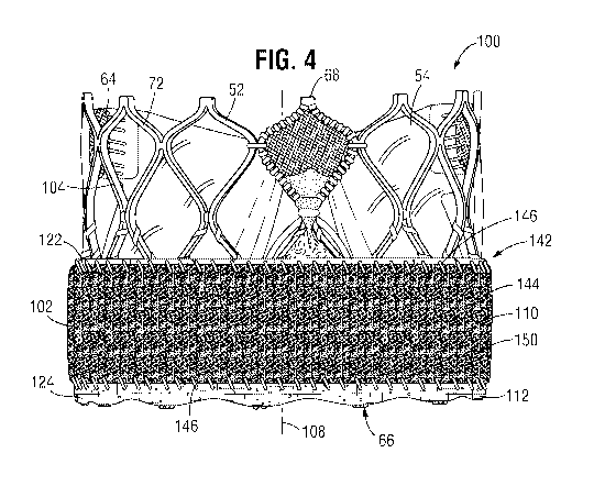
the frame and on an outer surface of the frame. The sealing member can include
a woven
inner layer and a knitted outer layer, the knitted outer layer configured to
promote tissue
growth and seal against native tissue when the valve is implanted and the
woven inner layer
configured to reduce tissue growth and protect leaflets of the leaflet
assembly from abrasion
from the inner layer. As such, end portions of the inner layer can overlap end
portions of the
outer layer, forming tapered folds at either end of the sealing member.
[008] In one representative embodiment, a prosthetic heart valve includes: a
frame
comprising a plurality of struts, the frame being radially collapsible and
expandable between
a collapsed configuration and an expanded configuration, the frame having an
inflow end and
an outflow end; at leaflet structure situated at least partially within the
frame; and a sealing
member disposed around an outer surface of the frame. The sealing member
includes: an
inner layer comprising a woven fabric; and an outer layer comprising a knitted
fabric. The
knitted fabric comprises a base layer including a plurality of courses formed
from a first base
yarn and a second base yarn that are knit together and a plurality of wales
formed from a
- 2 -
CA 03142469 2021-11-30
WO 2021/202636 PCT/US2021/025045
warp yarn, where each loop of the warp yarn is knit together with the first
base yarn and
second base yarn of two adjacent courses. The inner layer is arranged against
the outer
surface of the frame and the outer layer is arranged against and attached to
the inner layer and
the inner layer is folded over at either end, in an axial direction relative
to a central
longitudinal axis of the frame, to form folds that overlap respective ends of
the outer layer.
[009] In another representative embodiment, a prosthetic heart valve includes:
a frame
comprising a plurality of struts, the frame being radially collapsible and
expandable between
a collapsed configuration and an expanded configuration, the frame having an
inflow end and
an outflow end; at leaflet structure situated at least partially within the
frame; and a sealing
member disposed around an outer surface of the frame, the sealing member
extending in an
axial direction from the inflow end to a mid-point of the frame, the axial
direction relative to
a central longitudinal axis of the frame, the mid-point arranged between the
inflow end and
outflow end. The sealing member includes: an inner layer comprising a woven
fabric; and an
outer layer comprising a knitted fabric, the knitted fabric comprising a base
layer formed
from a first base yarn and a second base yarn that are knit together and a
plush outer surface
formed from a plurality of pile yarns that are knit into loops and that extend
outward from the
base layer. The inner layer is arranged against the outer surface of the frame
and the outer
layer is arranged against and attached to the inner layer and wherein the
inner layer is folded
over at both ends of the sealing member, the ends arranged opposite one
another along the
axial direction, to form folds that overlap respective ends of the outer
layer.
[010] In yet another representative embodiment, a prosthetic heart valve
includes: a frame
comprising a plurality of struts, the frame being radially collapsible and
expandable between
a collapsed configuration and an expanded configuration, the frame having an
inflow end and
an outflow end; at leaflet structure situated at least partially within the
frame; and a sealing
member disposed around an outer surface of the frame, the sealing member
extending in an
axial direction from the inflow end to a mid-point of the frame, the axial
direction relative to
a central longitudinal axis of the frame, the mid-point arranged between the
inflow end and
outflow end. The sealing member includes: an inner layer comprising a woven
fabric; and an
outer layer comprising a knitted fabric. The knitted fabric includes: a base
layer including a
plurality of courses formed from a first base yarn and a second base yarn that
are knit
together and a plurality of wales formed from a warp yarn, where each loop of
the warp yarn
- 3 -
CA 03142469 2021-11-30
WO 2021/202636 PCT/US2021/025045
is knit together with the first base yarn and second base yarn of two adjacent
courses; and a
plush outer surface formed from a plurality of pile yarns that are knit into
loops and that
extend outward from the base layer. The inner layer is arranged against the
outer surface of
the frame and the outer layer is arranged against and attached to the inner
layer and the inner
layer is folded over at either end of the sealing member to form tapered
folds, each tapered
fold overlapping a respective end of the outer layer at a wider portion of the
tapered fold.
[011] The foregoing and other objects, features, and advantages of the
disclosed technology
will become more apparent from the following detailed description, which
proceeds with
reference to the accompanying figures.
BRIEF DESCRIPTION OF THE DRAWINGS
[012] FIG. 1 is a perspective view of a prosthetic heart valve, according to
one embodiment.
[013] FIG. 2A is a perspective view of a prosthetic heart valve, according to
another
embodiment.
[014] FIG. 2B is a perspective view of the prosthetic valve of FIG. 2A with
the components
on the outside of the frame shown in transparent lines for purpose of
illustration.
[015] FIG. 3 is a cross-sectional, side view of a multi-layer skirt arranged
around a
circumference of an outer surface of a frame of an exemplary prosthetic heart
valve.
[016] FIG. 4 is a side view of the multi-layer skirt arranged around the
circumference of the
outer surface of the frame of the exemplary prosthetic heart valve of FIG. 3.
[017] FIG. 5 is a detail view of a portion of an inner surface of the frame
and the multi-layer
skirt of the exemplary prosthetic heart valve of FIG. 3.
[018] FIG. 6 is a perspective, exploded view of the multi-layer skirt of FIGS.
3-5, prior to
the layers of the multi-layer skirt being secured together.
[019] FIG. 7 is a schematic of an exemplary outer layer of a multi-layer
skirt, illustrating the
different yarn components that are knit together to form the outer layer.
[020] FIG. 8 is a micrograph of a loop side of an exemplary outer layer of a
multi-layer
skirt.
- 4 -
CA 03142469 2021-11-30
WO 2021/202636 PCT/US2021/025045
[021] FIG. 9 is a micrograph of a mesh side, or base layer, of the exemplary
outer layer of
the multi-layer skirt.
[022] FIG. 10 is a micrograph of an exemplary inner layer of a multi-layer
skirt.
[023] FIG. 11 is a detail view of a portion of the micrograph of FIG. 10,
illustrating the
woven configuration of the inner layer.
[024] FIG. 12 is a side view of the prosthetic heart valve including the multi-
layer skirt of
FIG. 4, in a first expanded state where the valve in expanded to its target
diameter.
[025] FIG. 13 is a side view of the prosthetic heart valve including the multi-
layer skirt of
FIG. 4, in a second expanded state where the valve in under deployed relative
to the
configuration of FIG. 12.
[026] FIG. 14 is a side view of the prosthetic heart valve including the multi-
layer skirt of
FIG. 4, in a third expanded state where the valve in expanded to an over
deployed state
relative to the configuration of FIG. 12.
[027] FIG. 15 is a side view of the prosthetic heart valve including the multi-
layer skirt of
FIG. 4, crimped onto a delivery device.
[028] FIG. 16 is a side view of an embodiment of a delivery apparatus
configured to deliver
and implant a radially expandable prosthetic heart valve at an implantation
site.
DETAILED DESCRIPTION
General Considerations
[029] For purposes of this description, certain aspects, advantages, and novel
features of the
embodiments of this disclosure are described herein. The described methods,
systems, and
apparatus should not be construed as limiting in any way. Instead, the present
disclosure is
directed toward all novel and non-obvious features and aspects of the various
disclosed
embodiments, alone and in various combinations and sub-combinations with one
another.
The disclosed methods, systems, and apparatus are not limited to any specific
aspect, feature,
or combination thereof, nor do the disclosed methods, systems, and apparatus
require that any
one or more specific advantages be present, or problems be solved.
- 5 -
CA 03142469 2021-11-30
WO 2021/202636 PCT/US2021/025045
[030] Features, integers, characteristics, compounds, chemical moieties, or
groups described
in conjunction with a particular aspect, embodiment or example of the
disclosure are to be
understood to be applicable to any other aspect, embodiment or example
described herein
unless incompatible therewith. All of the features disclosed in this
specification (including
any accompanying claims, abstract, and drawings), and/or all of the steps of
any method or
process so disclosed, may be combined in any combination, except combinations
where at
least some of such features and/or steps are mutually exclusive. The
disclosure is not
restricted to the details of any foregoing embodiments. The disclosure extends
to any novel
one, or any novel combination, of the features disclosed in this specification
(including any
accompanying claims, abstract, and drawings), or to any novel one, or any
novel
combination, of the steps of any method or process so disclosed.
[031] Although the operations of some of the disclosed methods are described
in a
particular, sequential order for convenient presentation, it should be
understood that this
manner of description encompasses rearrangement, unless a particular ordering
is required by
specific language set forth below. For example, operations described
sequentially may in
some cases be rearranged or performed concurrently. Moreover, for the sake of
simplicity,
the attached figures may not show the various ways in which the disclosed
methods, systems,
and apparatus can be used in conjunction with other systems, methods, and
apparatus.
[032] As used herein, the terms "a," "an," and "at least one" encompass one or
more of the
specified element. That is, if two of a particular element are present, one of
these elements is
also present and thus "an" element is present. The terms "a plurality of' and
"plural" mean
two or more of the specified element.
[033] As used herein, the term "and/or" used between the last two of a list of
elements
means any one or more of the listed elements. For example, the phrase "A, B,
and/or C"
means "A," "B," "C," "A and B," "A and C," "B and C," or "A, B, and C."
[034] As used herein, the term "coupled" generally means physically coupled or
linked and
does not exclude the presence of intermediate elements between the coupled
items absent
specific contrary language.
[035] Directions and other relative references (e.g., inner, outer, upper,
lower, etc.) may be
used to facilitate discussion of the drawings and principles herein, but are
not intended to be
- 6 -
CA 03142469 2021-11-30
WO 2021/202636 PCT/US2021/025045
limiting. For example, certain terms may be used such as "inside," "outside,",
"top,"
"down," "interior," "exterior," and the like. Such terms are used, where
applicable, to
provide some clarity of description when dealing with relative relationships,
particularly with
respect to the illustrated embodiments. Such terms are not, however, intended
to imply
absolute relationships, positions, and/or orientations. For example, with
respect to an object,
an "upper" part can become a "lower" part simply by turning the object over.
Nevertheless, it
is still the same part and the object remains the same. As used herein,
"and/or" means "and"
or "or," as well as "and" and "or."
[036] As used herein, with reference to the prosthetic heart valve and the
delivery apparatus,
"proximal" refers to a position, direction, or portion of a component that is
closer to the user
and/or a handle of the delivery apparatus that is outside the patient, while
"distal" refers to a
position, direction, or portion of a component that is further away from the
user and/or the
handle of the delivery apparatus and closer to the implantation site. The
terms "longitudinal"
and "axial" refer to an axis extending in the proximal and distal directions,
unless otherwise
expressly defined. Further, the term "radial" refers to a direction that is
arranged
perpendicular to the axis and points along a radius from a center of an object
(where the axis
is positioned at the center, such as the longitudinal axis of the prosthetic
valve).
Examples of the Disclosed Technology
[037] Described herein are examples of prosthetic heart valves, coverings or
sealing
members for prosthetic heart valves, and methods of making coverings or
sealing members
for prosthetic heart valves. The prosthetic heart valves may include a frame,
a leaflet
assembly including a plurality of leaflets arranged on and attached to an
inner surface of the
frame, and a sealing member arranged on and around an outer surface of the
frame.
[038] In some embodiments, the sealing member can comprise a woven inner layer
and a
knitted outer layer. The sealing member can include an upper (or outflow) fold
formed by an
upper end portion (outflow end portion) of the inner layer folded over itself
and extending
inward to overlap an upper end portion (outflow end portion) of the outer
layer and a lower
(or inflow) fold formed by a lower end portion (inflow end portion) of the
inner layer folded
over itself and extending inward to overlap a lower end portion (inflow end
portion) of the
outer layer. The upper fold can be arranged at a mid-point of the frame and
the lower fold
- 7 -
CA 03142469 2021-11-30
WO 2021/202636 PCT/US2021/025045
can be arranged at an inflow end of the frame. The upper and lower folds
(which can also be
referred to herein as first and second folds) create a taper at either end of
the sealing member,
thereby reducing an overall crimp profile of the valve and reducing push
forces during
delivery of the valve, crimped onto a delivery device, through an introducer
sheath and to a
target implantation site.
[039] The outer layer can be configured to promote tissue growth and seal with
native tissue
of an annulus of a heart (e.g., after implantation of the valve). The inner
layer can be
configured to decrease tissue growth and block the leaflets from contacting an
inner or back
surface of the outer layer, thereby reducing potential abrasion to the
leaflets.
[040] Embodiments of the disclosed technology, including the disclosed sealing
members or
skirts, can be used in combination with various prosthetic heart valves
configured for
implantation at various locations within the heart.
[041] FIG. 1 shows a prosthetic heart valve 10, according to one embodiment.
Any of the
prosthetic valves disclosed herein are adapted to be implanted in the native
aortic annulus,
although in other embodiments they can be adapted to be implanted in the other
native
annuluses of the heart (e.g., the pulmonary, mitral, and tricuspid valves).
The disclosed
prosthetic valves also can be implanted within vessels communicating with the
heart,
including a pulmonary artery (for replacing the function of a diseased
pulmonary valve, or
the superior vena cava or the inferior vena cava (for replacing the function
of a diseased
tricuspid valve).
[042] The prosthetic valve 10 can have four main components: a stent or frame
12, a
valvular structure 14, an inner skirt 16, and a perivalvular outer sealing
member or outer skirt
18. The prosthetic valve 10 can have an inflow end portion 15, an intermediate
portion 17,
and an outflow end portion 19. The inner skirt 16 can be arranged on and/or
coupled to an
inner surface of the frame 12 while the outer skirt 18 can be arranged on
and/or coupled to an
outer surface of the frame 12.
[043] The valvular structure 14 can comprise three leaflets 40, collectively
forming a leaflet
structure, which can be arranged to collapse in a tricuspid arrangement,
although in other
embodiments there can be greater or fewer number of leaflets (e.g., one or
more leaflets 40).
The leaflets 40 can be secured to one another at their adjacent sides to form
commissures 22
- 8 -
CA 03142469 2021-11-30
WO 2021/202636 PCT/US2021/025045
of the leaflet structure 14. The lower edge of valvular structure 14 can have
an undulating,
curved scalloped shape and can be secured to the inner skirt 16 by sutures
(not shown). In
some embodiments, the leaflets 40 can be formed of pericardial tissue (e.g.,
bovine
pericardial tissue), biocompatible synthetic materials, or various other
suitable natural or
synthetic materials as known in the art and described in U.S. Patent No.
6,730,118, which is
incorporated by reference herein.
[044] The frame 12 can be formed with a plurality of circumferentially spaced
slots, or
commissure windows 20 that are adapted to mount the commissures 22 of the
valvular
structure 14 to the frame. The frame 12 can be made of any of various suitable
plastically-
expandable materials (e.g., stainless steel, etc.) or g-expanding materials
(e.g., nickel titanium
alloy (NiTi), such as nitinol), as known in the art. In some embodiments, when
constructed
of a plastically-expandable material, the frame 12 (and thus the prosthetic
valve 10) can be
crimped to a radially collapsed configuration on a delivery catheter and then
expanded inside
a patient by an inflatable balloon or equivalent expansion mechanism. When
constructed of a
self-expandable material, the frame 12 (and thus the prosthetic valve 10) can
be crimped to a
radially collapsed configuration and restrained in the collapsed configuration
by insertion into
a sheath or equivalent mechanism of a delivery catheter. Once inside the body,
the prosthetic
valve can be advanced from the delivery sheath, which allows the prosthetic
valve to expand
to its functional size.
[045] Suitable plastically-expandable materials that can be used to form the
frame 12
include, without limitation, stainless steel, a biocompatible, high-strength
alloys (e.g., a
cobalt-chromium or a nickel-cobalt-chromium alloys), polymers, or combinations
thereof. In
particular embodiments, frame 12 is made of a nickel-cobalt-chromium-
molybdenum alloy,
such as MP35N alloy (SPS Technologies, Jenkintown, Pennsylvania), which is
equivalent to
UNS R30035 alloy (covered by ASTM F562-02). MP35N alloy/UNS R30035 alloy
comprises 35% nickel, 35% cobalt, 20% chromium, and 10% molybdenum, by weight.
Additional details regarding the prosthetic valve 10 and its various
components are described
in WIPO Patent Application Publication No. WO 2018/222799, which is
incorporated herein
by reference.
- 9 -
CA 03142469 2021-11-30
WO 2021/202636 PCT/US2021/025045
[046] FIG. 2A is a perspective view of a prosthetic heart valve 50, according
to another
embodiment. The valve 50 can have three main components: a stent or frame, 52,
a valvular
structure 54, and a sealing member 56. FIG. 2B is a perspective view of the
prosthetic valve
50 with the components on the outside of the frame 52 (including the sealing
member 56)
shown in transparent lines for purposes of illustration.
[047] Like the valvular structure 14 of FIG. 1, the valvular structure 54 can
comprise three
leaflets 60, collectively forming a leaflet structure, which can be arranged
to collapse in a
tricuspid arrangement. Each leaflet 60 can be coupled to the frame 52 along
its inflow edge
62 (the lower edge in the figures; also referred to as "cusp edges") and at
commissures 64 of
the valvular structure 54 where adjacent portions of two leaflets are
connected to each other.
A reinforcing element (not shown), such as a fabric strip, can be connected
directly to the
cusp edges of the leaflets and to the struts of the frame to couple the cusp
edges of the leaflets
to the frame.
[048] Similar to the frame 12 of FIG. 1, the frame 52 can be made of any of
various suitable
plastically-expandable materials or self-expanding materials, as known in the
art and
described above. The frame 52 in the illustrated embodiment comprises a
plurality of
circumferentially extending rows of angled struts 72 defining rows of cells,
or openings, 74
of the frame. The frame 52 can have a cylindrical or substantially cylindrical
shape having a
constant diameter from an inflow end 66 to an outflow end 68 of the frame as
shown, or the
frame can vary in diameter along the height of the frame, as disclosed in U.S.
Patent
Publication No. 2012/0239142, which is incorporated herein by reference.
[049] The sealing member 56 in the illustrated embodiment is mounted on the
outside of the
frame 52 and functions to create a seal against the surrounding tissue (e.g.,
the native leaflets
and/or native annulus) to prevent or at least minimize paravalvular leakage.
The sealing
member 56 can comprise an inner layer 76 (which can be in contact with the
outer surface of
the frame 52) and an outer layer 78. The sealing member 56 can be connected to
the frame
52 using suitable techniques or mechanisms. For example, the sealing member 56
can be
sutured to the frame 52 via sutures that can extend around the struts 72 and
through the inner
layer 76. In alternative embodiments, the inner layer 76 can be mounted on the
inner surface
of the frame 52, while the outer layer 78 is on the outside of the frame 52.
- 10 -
CA 03142469 2021-11-30
WO 2021/202636 PCT/US2021/025045
[050] The outer layer 78 can be configured or shaped to extend radially
outward from the
inner layer 76 and the frame 52 when the prosthetic valve 50 is deployed. When
the
prosthetic valve is fully expanded outside of a patient's body, the outer
layer 78 can expand
away from the inner layer 76 to create a space between the two layers. Thus,
when implanted
inside the body, this allows the outer layer 78 to expand into contact with
the surrounding
tissue, such as a native annulus.
[051] Additional details regarding the prosthetic valve 50 and its various
components are
described in U.S. Patent Publication No. 2018/0028310, which is incorporated
herein by
reference.
[052] FIG. 16 shows a delivery apparatus 400, according to an embodiment, that
can be
used to implant an expandable prosthetic heart valve (e.g., prosthetic heart
valve 10 of FIG. 1,
prosthetic heart valve 50 of FIGS. 2A-2B, or any of the other prosthetic heart
valves
described herein). In some embodiments, the delivery apparatus 400 is
specifically adapted
for use in introducing a prosthetic valve into a heart.
[053] The delivery apparatus 400 in the illustrated embodiment of FIG. 16 is a
balloon
catheter comprising a handle 402 and a steerable, outer shaft 404 extending
distally from the
handle 402. The delivery apparatus 400 can further comprise an intermediate
shaft 406
(which also may be referred to as a balloon shaft) that extends proximally
from the handle
402 and distally from the handle 402, the portion extending distally from the
handle 402 also
extending coaxially through the outer shaft 404. Additionally, the delivery
apparatus 400 can
further comprise an inner shaft 408 extending distally from the handle 402
coaxially through
the intermediate shaft 406 and the outer shaft 404 and proximally from the
handle 402
coaxially through the intermediate shaft 406.
[054] The outer shaft 404 and the intermediate shaft 406 can be configured to
translate (e.g.,
move) longitudinally, along a central longitudinal axis 420 of the delivery
apparatus 400,
relative to one another to facilitate delivery and positioning of a prosthetic
valve at an
implantation site in a patient's body.
[055] The intermediate shaft 406 can include a proximal end portion 410 that
extends
proximally from a proximal end of the handle 402, to an adaptor 412. A
rotatable knob 414
can be mounted on the proximal end portion 410 and can be configured to rotate
the
- 11-
CA 03142469 2021-11-30
WO 2021/202636 PCT/US2021/025045
intermediate shaft 406 around the central longitudinal axis 420 and relative
to the outer shaft
404.
[056] The adaptor 412 can include a first port 438 configured to receive a
guidewire
therethrough and a second port 440 configured to receive fluid (e.g.,
inflation fluid) from a
fluid source. The second port 440 can be fluidly coupled to an inner lumen of
the
intermediate shaft 406.
[057] The intermediate shaft 406 can further include a distal end portion that
extends
distally beyond a distal end of the outer shaft 404 when a distal end of the
outer shaft 404 is
positioned away from an inflatable balloon 418 of the delivery apparatus 400.
A distal end
portion of the inner shaft 408 can extend distally beyond the distal end
portion of the
intermediate shaft 406.
[058] The balloon 418 can be coupled to the distal end portion of the
intermediate shaft 406.
[059] In some embodiments, a distal end of the balloon 418 can be coupled to a
distal end of
the delivery apparatus 400, such as to a nose cone 422 (as shown in FIG. 16),
or to an
alternate component at the distal end of the delivery apparatus 400 (e.g., a
distal shoulder).
An intermediate portion of the balloon 418 can overlay a valve mounting
portion 424 of a
distal end portion of the delivery apparatus 400 and a distal end portion of
the balloon 418
can overly a distal shoulder 426 of the delivery apparatus 400. The valve
mounting portion
424 and the intermediate portion of the balloon 418 can be configured to
receive a prosthetic
heart valve in a radially compressed state. For example, as shown
schematically in FIG. 16, a
prosthetic heart valve 450 (which can be one of the prosthetic valves
described herein) can be
mounted around the balloon 418, at the valve mounting portion 424 of the
delivery apparatus
400.
[060] The balloon shoulder assembly, including the distal shoulder 426, is
configured to
maintain the prosthetic heart valve 450 (or other medical device) at a fixed
position on the
balloon 418 during delivery through the patient's vasculature.
[061] The outer shaft 404 can include a distal tip portion 428 mounted on its
distal end. The
outer shaft 404 and the intermediate shaft 406 can be translated axially
relative to one another
to position the distal tip portion 428 adjacent to a proximal end of the valve
mounting portion
424, when the prosthetic valve 450 is mounted in the radially compressed state
on the valve
- 12 -
CA 03142469 2021-11-30
WO 2021/202636 PCT/US2021/025045
mounting portion 424 (as shown in FIG. 16) and during delivery of the
prosthetic valve to the
target implantation site. As such, the distal tip portion 428 can be
configured to resist
movement of the prosthetic valve 450 relative to the balloon 418 proximally,
in the axial
direction, relative to the balloon 418, when the distal tip portion 428 is
arranged adjacent to a
proximal side of the valve mounting portion 424.
[062] An annular space can be defined between an outer surface of the inner
shaft 408 and
an inner surface of the intermediate shaft 406 and can be configured to
receive fluid from a
fluid source via the second port 440 of the adaptor 412. The annular space can
be fluidly
coupled to a fluid passageway formed between the outer surface of the distal
end portion of
the inner shaft 408 and an inner surface of the balloon 418. As such, fluid
from the fluid
source can flow to the fluid passageway from the annular space to inflate the
balloon 418 and
radially expand and deploy the prosthetic valve 450.
[063] An inner lumen of the inner shaft can be configured to receive a
guidewire
therethrough, for navigating the distal end portion of the delivery apparatus
400 to the target
implantation site.
[064] The handle 402 can include a steering mechanism configured to adjust the
curvature
of the distal end portion of the delivery apparatus 400. In the illustrated
embodiment, for
example, the handle 402 includes an adjustment member, such as the illustrated
rotatable
knob 460, which in turn is operatively coupled to the proximal end portion of
a pull wire.
The pull wire can extend distally from the handle 402 through the outer shaft
404 and has a
distal end portion affixed to the outer shaft 404 at or near the distal end of
the outer shaft 404.
Rotating the knob 460 can increase or decrease the tension in the pull wire,
thereby adjusting
the curvature of the distal end portion of the delivery apparatus 400. Further
details on
steering or flex mechanisms for the delivery apparatus can be found in U.S.
Patent No.
9,339,384, which is incorporated by reference herein.
[065] The handle 402 can further include an adjustment mechanism 461 including
an
adjustment member, such as the illustrated rotatable knob 462, and an
associated locking
mechanism including another adjustment member, configured as a rotatable knob
478. The
adjustment mechanism 461 is configured to adjust the axial position of the
intermediate shaft
406 relative to the outer shaft 404 (e.g., for fine positioning at the
implantation site). Further
- 13 -
CA 03142469 2021-11-30
WO 2021/202636 PCT/US2021/025045
details on the delivery apparatus 400 can be found in U.S. Provisional
Application Nos.
63/069,567 and 63/138,890, which are incorporated by reference herein.
[066] In some embodiments, prosthetic heart valves can include a single-layer
sealing
member or outer skirt that comprises a woven material. However, this type of
skirt can be
expensive to manufacture and not seal well against the tissue of a native
annulus of the heart.
In some embodiments, a two-layer sealing member or outer skirt comprising
different
materials or differently constructed materials (e.g., a same material with
different cloth or
fabric construction) may help to address some of these issues, such as
improving sealing
against the native tissue while reducing costs. However, two-layer skirts may
be bulky and
increase pushing forces through an introducer of a valve delivery system,
thereby increasing a
difficulty in delivering a compressed valve to a target implantation site in
the heart. Further,
outer layers of two-layer skirts may cause abrasion against the leaflets of
the valve, which
may decrease their longevity.
[067] FIGS. 3-15 show an embodiment of a two-layer skirt (e.g., sealing member
or
covering) 102 for a prosthetic heart valve that is configured to promote
tissue growth and
provide increased sealing against tissue of a native annulus of the heart
while also protecting
the leaflets of the prosthetic heart valve and reducing push forces
experienced during delivery
of the valve to the target implantation site in the heart. For example, FIG. 3
shows a cross-
sectional, side view of the skirt 102 on an exemplary prosthetic heart valve.
FIGS. 4 and 5
show an outer view and inner view, respectively, of the skirt 102 on the
exemplary prosthetic
heart valve. FIGS. 6-11 show different views or portions of the skirt 102,
highlighting the
specific cloth construction of the two layers of the skirt 102. FIGS. 12-14
show the skirt 102
on the exemplary prosthetic heart valve in different stages of deployment
(e.g., during
implantation at the target implantation site), while FIG. 15 shows the skirt
102 on the
exemplary prosthetic heart valve, where the valve is in a crimped state on a
delivery device.
[068] It should be noted that while the skirt 102 is shown on the valve 100
including the
frame 52 and the valvular structure 54 in FIGS. 3-5 and 12-15, as described
further below, in
alternate embodiments, the skirt 102 may be arranged on an outer surface of a
different type
of frame of a different prosthetic heart valve. For example, in some
embodiments, the skirt
102 may replace the outer skirt 18 of prosthetic heart valve 10 of FIG. 1.
- 14 -
CA 03142469 2021-11-30
WO 2021/202636 PCT/US2021/025045
[069] Turning first to FIG. 3, a side view of a prosthetic heart valve 100,
according to an
embodiment, is shown. The valve 100 includes the frame 52 and valvular
structure 54 of the
valve 50 shown in FIGS. 2A and 2B. However, the valve 100 includes a different
outer
sealing member (also referred to herein as an "outer covering" or "skirt") 102
from that of the
valve 50. The skirt 102 is shown in cross-section in FIG. 3 to illustrate its
different layers.
[070] The skirt 102 is arranged on an outer surface 104 of the frame 52, where
the outer
surface 104 is arranged opposite an inner surface 106 of the frame 52, the
inner and outer
surfaces relative to a radial direction that is relative to a central
longitudinal axis 108 of the
valve 100. As shown in FIG. 3, the commissures 64 are attached to the inner
surface 106
while the outer skirt 102 is arranged on the outer surface, around an entire
circumference of
the frame 52 (e.g., as shown in FIG. 4, as described further below).
[071] As introduced above and shown in FIG. 3, the skirt 102 is a two-layer
skirt 102
including an outer layer 110 and an inner layer 112 which are coupled to one
another. In
some embodiments, the outer layer 110 can comprise a knitted, woven, braided,
or non-
woven material, which may result in a softer, plush (e.g., fuzzy) surface in
appearance and/or
texture. In some embodiments, the inner layer 112 can comprise a woven
material. The
outer layer 110 may be configured to promote tissue growth for sealing of the
valve 100
against the native tissue (e.g., when implanted), while the inner layer may be
configured to
reduce tissue growth and protect the leaflets of the valvular structure 54
from abrasions from
the outer layer 110. Further details on the material construction of the outer
layer 110 and
inner layer 112 of the skirt 102 are discussed below with reference to FIGS. 4-
11.
[072] As shown in FIG. 3, an inner (e.g., radially inward-facing) surface of
the inner layer
112 is arranged adjacent to and positioned against the outer surface 104 of
the struts of the
frame 52, along and around an entire circumference of the frame 52 (as shown
in FIG. 4, for
example). Further, the outer layer 110 is disposed on (e.g., positioned
against) the inner layer
112. More specifically, an inner (e.g., radially inward-facing) surface of the
outer layer 110
is in face-sharing contact with an outer (e.g., radially outward-facing)
surface of the inner
layer 112.
[073] In some embodiments, as shown in FIG. 3, the skirt 102 extends, in an
axial direction
relative to the central longitudinal axis 108, from inflow apices 114 of the
frame 52 (e.g.,
- 15 -
CA 03142469 2021-11-30
WO 2021/202636 PCT/US2021/025045
apices arranged at the inflow end 66) to a location approximately mid-way
between the
outflow end 68 and the inflow end 66 of the frame 52 (e.g., approximately mid-
frame). In
some embodiments, the skirt 102 can extend to a mid-point of the frame, in the
axial
direction, that is equidistant between the outflow end 68 and the inflow end
66. In other
embodiments, the skirt 102 can extend to a mid-point of the frame, in the
axial direction, that
is arranged between the outflow end 68 and the inflow end 66, but closer to
the inflow end 66
than the outflow end 68. In still other embodiments, the skirt 102 can extend
to a mid-point
of the frame, in the axial direction, that is arranged between the outflow end
68 and the
inflow end 66, but closer to the outflow end 68 than the inflow end 66. In
other
embodiments, the skirt 102 can extend the entire height or substantially the
entire of the
frame from the inflow end 66 to the outflow end 68. In other embodiments, the
skirt 102 can
extend from the outflow end 68 to a location offset and downstream of the
inflow end 66. In
still other embodiments, the skirt 102 can be offset upstream from the outflow
end 68 and
offset downstream from the inflow end 66.
[074] As shown in FIG. 3, the inner layer 112 can have a length 116 (arranged
in the axial
direction) that is shorter than a length 118 of the frame 52 and longer than a
length 120 of the
outer layer 110. While the inner layer 112 can extend from the inflow apices
114 to the mid-
point of the frame 52, the outer layer 110 can extend from a first point that
is a distance away
(e.g., inward along the axial direction) from the inflow apices 114 to a
second point that is a
distance away from (e.g., short of) the mid-point of the frame 52. In some
embodiments, the
first point may be at or proximate to a first rung 140 of the frame 52.
[075] By having the inner layer 112 and the outer layer 110 of the skirt have
different
lengths, as explained above, the overall crimp profile of the valve 100 may be
reduced (e.g.,
as shown in FIG. 15). Further, by having the outer layer 110 not extend all
the way to the
inflow end 66 of the frame (e.g., to the inflow apices), the crimp profile at
the bulkier, inflow
end 66 of the valve 100 may be reduced. While the length 120 of the outer
layer 110 is
reduced relative to the length 116 of the inner layer 112, the length 120 of
the outer layer 110
can still be selected to provide the largest possible surface area for contact
with the native
tissue, once implanted.
- 16-
CA 03142469 2021-11-30
WO 2021/202636 PCT/US2021/025045
[076] In some embodiments the length 116 of the inner layer 112 can be in a
range of 13-17
mm and the length 120 of the outer layer 110 can be in a range of 7.0-15 mm.
In other
embodiments, the length 116 of the inner layer 112 can be in a range of 13-17
mm and the
length 120 of the outer layer 110 can be in a range of 7-13 mm.
[077] The length 116 of the inner layer 112 may be an effective, folded length
of the inner
layer 112 when assembled on the frame (e.g., as shown on the valve in FIG. 3).
However, the
unfolded, manufactured length of the inner layer (length 117 shown in FIG. 6)
is longer, in
order to accommodate the folds over the ends of the outer layer 110. For
example, as shown
in FIG. 3, the skirt 102 includes an upper, first fold 122 arranged at the end
of the skirt 102
located closest to the outflow end 68 of the frame 52 and a lower, second fold
124 arranged at
the end of the skirt 102 located closest to the inflow end 66 of the frame 52.
Said another
way, the second fold 124 is arranged at (e.g., proximate to) the inflow apices
114 of the frame
52 and the first fold 122 is arranged further away from the inflow apices 114
(than the second
fold 124).
[078] Each of the first fold 122 and the second fold 124 are formed by a
different (opposite)
ends of the inner layer 112. For example, the first fold 122 is formed by
folding an upper or
outflow, first end of the inner layer 112 over from an axially-extending, main
portion 126 of
the inner layer 112, at a location arranged outward, in the axial direction,
from an upper or
outflow, first end portion 128 of the outer layer 110 (e.g., the end arranged
closer to the
outflow end 68), and over the first end portion 128 of the outer layer 110. As
a result, a first
end portion 130 of the inner layer 112 overlaps the outer surface of the first
end portion 128
of the outer layer 110.
[079] Similarly, the second fold 124 is formed by folding a lower or inflow,
second end of
the inner layer 112 over from the axially-extending, main portion 126 of the
inner layer 112,
at a location arranged outward, in the axial direction, from a lower or
inflow, second end
portion 132 of the outer layer 110 (e.g., the end arranged closer to the
inflow end 66), and
over the second end portion 132 of the outer layer 110. As a result, a second
end portion 134
of the inner layer 112 overlaps the outer surface of the second end portion
132 of the outer
layer 110.
- 17 -
CA 03142469 2021-11-30
WO 2021/202636 PCT/US2021/025045
[080] As shown in FIG. 3, each of the first fold 122 and the second fold 124
creates a taper
(e.g., narrower portion) at either end of the skirt 102. For example, each
axial end of the skirt
102 has a wider portion 136 formed by overlapping layers of the inner layer
112 and the outer
layer 110 (e.g., three overlapping layers in total) and a narrower portion 138
formed by two
overlapping layers of the inner layer 112. The narrower portion 138 is
arranged outward, in
the axial direction, from the wider portion 136. As a result, the ends of the
skirt 102 each
taper (e.g., narrow) from the respective end of the outer layer 110 to the
respective end of the
skirt 102.
[081] The first fold 122 may help to cover, and therefore protect, the
leaflets from the fuzzy
or plush edges of the outer layer 110, thereby reducing abrasion to the
leaflets. The second
fold 124 may help to reduce push forces when inserting the prosthetic heart
valve, crimped
onto a delivery device (e.g., as shown in FIG. 15), into and through an
introducer sheath,
when advancing the valve to the target implantation site.
[082] For example, as shown in FIG. 15, the valve 100, including the frame 52
and the skirt
102, can be crimped onto a delivery device 300. In some embodiments, as shown
in FIG. 15,
the valve 100 can be crimped onto the delivery device 300, inward of (proximal
to) a
nosecone 302 and between a proximal shoulder (disposed inside a proximal
section 304 of an
inflatable balloon of the delivery device 300) and distal shoulder (disposed
inside a distal
section 306 of the inflatable balloon) of the delivery device 300. As shown in
FIG. 15, the
overall crimp profile of the valve 100 may be reduced (e.g., as compared to
other valves
having multi-layer skirts) due to the construction of the inner and outer
layers of the skirt
102, as described herein (e.g., a crimped diameter of a skirt portion 310 of
the valve 100
including the skirt 102 may only be slightly larger than a crimped diameter of
a frame portion
312 of the valve 100 that does not include the skirt 102). Further, the
tapering of the lower
fold 124, arranged at the distal end 314 of the skirt (e.g., inflow end of
valve 100), the distal
end 314 arranged closest to the nosecone 302, may help to reduce push forces
when
advancing the valve 100, on the delivery device 300, into and through an
introducer coupled
with an introducer sheath inserted in a patient's vasculature.
[083] FIG. 4 shows an outer view (e.g., from outside the valve 100) of the
skirt 102 attached
to and extending around a circumference of the outer surface 104 of the valve
100. As
- 18 -
CA 03142469 2021-11-30
WO 2021/202636 PCT/US2021/025045
explained above with reference to FIG. 3 and is also shown in FIG. 4, the
skirt 102 extends,
in the axial direction, from the inflow end 66 of the valve 100 to a mid-point
142 of the valve
100.
[084] An exposed, outer surface 144 of the outer layer 110 is shown in FIG. 4,
with the
upper, first fold 122 and lower, second fold 124 extending above and below,
respectively, the
exposed, outer surface. In some embodiments, as shown in FIG. 4, the lower,
second fold
124 may be longer, in the axial direction, than the upper, first fold 122. As
explained above,
this configuration may help to reduce the crimp profile and overall bulkiness
of the valve 100
at the inflow end 66.
[085] In some embodiments, as shown in FIG. 4, the inner layer 112 and the
outer layer 110
of the skirt 102 are connected (e.g., coupled) together, at their folded over,
overlapping
regions (e.g., proximate to folds 122 and 124), via a plurality of whip
stitches 146. More
specifically, the whip stitches 146 can be made in the taper of each of the
folds 122 and 124
to allow for stretching between the valve's crimped and expanded
configurations (e.g., as
shown in FIGS. 12-14, as described further below). For example, a first line
of whip stitches
146 is arranged at the first fold 122, around the entire circumference of the
frame 52, and a
second line of whip stitches 146 is arranged at the second fold 124, around
the entire
circumference of the frame 52.
[086] As an example, FIGS. 12-14 show the valve 100 in three expanded (e.g.,
expanded
relative to a compressed or crimped configuration, as shown in FIG. 15)
configurations,
including a first expanded configuration 200 (FIG. 12), a second expanded
configuration 202
(FIG. 13), and a third expanded configuration 204 (FIG. 14). The first
expanded
configuration 200 shown in FIG. 12 shows the valve 100 in an exemplary, as
built, expanded
size (e.g., expanded to its target diameter). The second expanded
configuration 202 shown in
FIG. 13 shows the valve 100 in an under deployed state (e.g., expanded to a
diameter that is
smaller than its as built, or target diameter). In contrast, the third
expanded configuration 204
shown in FIG. 14 shows the valve 100 in an over deployed state (e.g., expanded
to a diameter
that is larger than its as built, or target diameter).
[087] Each of FIGS. 12-14 shows a varying degree of a scallop-like (e.g.,
undulating or
wave-like) shape to an inflow edge 206 of the skirt 102. The scallop or wave-
like shape of
- 19-
CA 03142469 2021-11-30
WO 2021/202636 PCT/US2021/025045
the inflow edge 206 can be created by the inflow edge 206 being arranged at
and/or attached
to each inflow apex 114 of the frame 52 and then undulating inward, away from
the inflow
end 66 and toward the outflow end 68, of the frame 52, creating an inward
crest (e.g., peak)
208 in the scalloped inflow edge 206 between each set of adjacent inflow
apices 114.
[088] For example, in the second expanded configuration (e.g., the under
deployed
configuration) 202 shown in FIG. 13, the inward crests 208 of the scalloped
inflow edge 206
are more pronounced (e.g., an amplitude of the wave-like inflow edge 206 is
greater than in
the other configurations shown in FIGS. 12 and 14). As the frame 52 is
expanded further, the
inflow edge 206 straightens out, thereby decreasing the amplitudes of the
crests 208. For
example, in the third expanded configuration (e.g., the over deployed
configuration) 204
shown in FIG. 14, the inflow edge 206 is almost completely straightened out,
making the
crests 208 almost disappear relative to a remainder of the inflow edge 206. In
this way, the
whip stitches 146 of the skirt allow for stretching of the skirt 102, between
the valve's
various expanded configurations. This may allow more flexibility in a final,
expanded
diameter of the valve 100.
[089] Returning to FIG. 4, in some embodiments, the whip stitches 146 can be
angled in a
same direction around the circumference of the frame 52 (and valve 100).
[090] As shown in FIGS. 4 and 5, both the inner layer 112 and the outer layer
110 of the
skirt 102 are arranged on the outer surface 104 of the frame 52. In some
embodiments, as
shown in FIGS. 3-5, the valve 100 does not have an additional, inner skirt
arranged on the
inner surface 106 of the frame 52.
[091] For example, as shown in FIG. 5, the skirt 102 is arranged against and
along the outer
surface 104 of the frame 52 and the leaflets 60 are arranged against and
attached to the inner
surface 106 of the frame 52. For example, the cusp edge portions of the
leaflets 60 can be
sutured to struts 72 that generally follow the contour of the cusp edge
portions of the leaflets.
In some embodiments, the skirt 102 is attached to the struts 72 of the frame
52 via one or
more fasteners (e.g., sutures) 148.
[092] In some embodiments, as shown in FIG. 5, a lower portion of the inner
layer 112 can
be secured to the struts 72 attached to the lower apices 114 via the one or
more fasteners 148
(e.g., sutures). For example, as shown in FIG. 5, the one or more fasteners
148 are connected
- 20 -
CA 03142469 2021-11-30
WO 2021/202636 PCT/US2021/025045
to at least the inner layer 112 and loop around the struts 72, at the apices
114, and/or loop
around the apices 114. In some embodiments, an upper (e.g., outflow) portion
of the inner
layer 112 can be further secured to the struts 72 arranged proximate to the
mid-point 142. In
some embodiments, additional portions of the inner layer 112 and/or the outer
layer 110 can
be secured to the struts 72 of the frame 52. In some embodiments, more or less
sutures than
those shown in FIG. 5 may be used to secure the lower portion of the inner
layer 112 to the
struts 72.
[093] FIG. 6 is a perspective, exploded view of the skirt 102, prior to the
outer layer 110
and the inner layer 112 being secured together. The inner layer 112 can be
referred to as a
woven layer and can comprise a woven material. In some embodiments, the woven
material
may be a plain woven cloth made of polyethylene terephthalate (PET) fabric
(e.g., Dacron).
In other embodiments, the woven material of the inner layer 112 can be another
type of
woven fabric, made up of an implantable polymer, such as Ultra High Molecular
Weight
Polyethylene (UHMWPE), Polytetrafluoroethylene (PTFE), Polypropylene,
thermoplastic
polyurethane (TPU), and polyetheretherketone (PEEK), In other embodiments, the
woven
material of the inner layer 112 can be a different type of weave structure
such satin, twill,
leno, or another derivative of a plain weave. In some embodiment the woven
material of the
inner layer 112 can be a cloth that is post treated by calendaring to reduce
the thickness of the
cloth that can be advantageous for a lower profile and surface modification
that may reduce
cell attachment, as well as tissue ingrowth and overgrowth. In some
embodiments, the
woven material of the inner layer 112 can be a cloth that is post treated by
applying a thin
coating of polymers such as thermoplastic polyurethane (TPU) over the inner
surface for
surface modification in order to actively resist tissue ingrowth or
overgrowth.
[094] In some embodiments, the inner layer 112 can also comprise a film
including any of a
variety of crystalline or semi-crystalline polymeric materials, such as
polytetrafluorethylene
(PTFE), PET, polypropylene, polyamide, polyetheretherketone (PEEK), TPU, etc.
In this
manner, the inner layer 112 can be relatively thin and yet strong enough to
allow the skirt 102
to be sutured to the frame, and to allow the prosthetic heart valve to be
crimped, without
tearing. Further details on the construction of the fabric of the inner layer
112 are discussed
below with reference to FIGS. 10 and 11. In some embodiments, the inner layer
112 can also
- 21 -
CA 03142469 2021-11-30
WO 2021/202636 PCT/US2021/025045
comprise an electrospun membrane including any of a variety of crystalline or
semi-
crystalline polymeric materials, such as polytetrafluorethylene (PTFE), PET,
UHMWPE, etc.
[095] In some embodiments, the outer layer 110 can be referred to as a knitted
layer and can
comprise a knitted material (e.g., knitted fabric). In some embodiments, the
knitted material
of the of the outer layer 110 can also comprise a knitted PET fabric. In other
embodiments,
the knitted material can comprise a different type of fiber or yarn (other
than PET fiber) such
as Nylon, ePTFE, TPU, or the like. In some embodiments, the outer layer 110
can comprise
a woven or nonwoven fabric made of PET or the like. As explained further below
with
reference to FIGS. 7-9, the outer layer 110 can be knitted, woven, or nonwoven
in such a way
that it comprises an outer soft, plush (e.g., fuzzy) surface 150 and a base
surface or layer 152.
[096] For example, the plush surface 150 can be a plush nap or pile of the
fabric of the outer
layer 110. Exemplary fabrics having a pile include velour, velvet, velveteen,
corduroy,
terrycloth, fleece, etc. As explained further below with reference to FIGS. 7-
9, the base layer
152 can comprise warp and base yarns (e.g., strands, etc.) knitted into a mesh-
like structure.
As shown in FIG. 6, the pile of the plush surface 150 (second layer) can
comprise pile strands
or yarn 154 that are knitted into loops and that extend from the base layer
152. These loop-
like yarns can help to increase the surface area of the outer layer 110 of the
skirt, thereby
providing faster sealing against the native tissue, after implantation. In
some embodiments,
the pile yarns (e.g., loop yarn) 154 can be separate strands/yarns that are
incorporated in the
base layer 152, as described further below with reference to FIGS. 7-9.
[097] The outer layer 110 can be attached (e.g., by sutures, thread, etc.) to
the inner layer
112 via a plurality of whip stitches 146, as explained above with reference to
FIG. 4. More
specifically, the inner surface 160 of the outer layer 110 can be positioned
against the outer
surface 162 of the inner layer 112, between dashed lines 156. For example, in
FIG. 6, the
location of the ends (e.g., ends of end portions 128 and 132) of the outer
layer 110 when the
outer layer 110 is attached to the inner layer 112, is represented as dashed
lines 156 on the
inner layer 112. Dashed lines 158 represent the location of where the
outermost, axial ends
of the inner layer 112 that are positioned against the outer surface of the
frame 52 would
begin to fold over to extend toward and over the outer, plush surface 150 of
the outer layer
110. Said another way, the dashed lines 158 represent where the bends of the
folds 122 and
124 are formed on the inner layer 112.
- 22 -
CA 03142469 2021-11-30
WO 2021/202636 PCT/US2021/025045
[098] Once the outer layer 110 and inner layer 112 are positioned in face-
sharing contact
with one another, as described above, they can be attached together via the
lines of whip
stitches 146, as shown in FIG. 4. In some embodiments, the lines of whip
stitches 146 can
extend between the outer layer 110 and inner layer 112, along its long
dimension (e.g., long
dimension shown in FIG. 6), in a region of the dashed lines 156 (e.g., at or
inward of dashed
lines 156).
[099] As shown in FIG. 6, the upper edge of the inner layer 112 and the upper
edge of the
outer layer 110 are offset from one another by distance dl (on the frame 52)
to create the
tapered, upper, first fold 122 and the lower edge of the inner layer 112 and
the lower edge of
the outer layer 110 are offset from one another by distance d2 (on the frame
52) to create the
tapered, lower, second fold 124. In some embodiments the distances dl and d2
may be the
same. In other embodiments, as shown in FIG. 3, the distance d2 may be longer
than the
distance dl to create a longer taper region at the inflow end of the valve.
[0100] In some embodiments, once the outer layer 110 is secured to the inner
layer 112, the
resulting skirt swatch can be folded and sutured into a cylindrical shape. The
resulting skirt
102 can then be secured to the frame 52 by attachment means, for example, by
suturing,
clipping, adhering, etc. it to the struts 72 (e.g., as shown in FIG. 5).
[0101] FIGS. 7-9 illustrate the cloth construction of the outer layer 110 in
more detail,
according to one embodiment. Specifically, FIG. 7 shows a schematic of the
different yarn
components that are knit together to form the plush surface 150 and the base
layer 152 of the
outer layer 110. As explained further below, the specific knit construction of
the outer layer
110 results in the plush surface 150 arranged on one side of the outer layer
110 (e.g., the loop
side) and a mesh-like surface (the base layer 152) arranged on the opposite,
other side of the
outer layer 110 (e.g., the mesh side). Micrographs of an exemplary outer layer
fabric
constructed according to the schematic of FIG. 7 are shown in FIG. 8 (showing
the plush
surface, or loop side) and FIG. 9 (showing the base layer or mesh side).
[0102] In some embodiments, the outer layer 110 can be constructed as a
crochet knitted
cloth. In some embodiments, the outer layer 110 can be referred to as a
crochet knit velour
cloth or fabric due to the yarns and knitting techniques that are used to
construct it, as
described further below.
-23 -
CA 03142469 2021-11-30
WO 2021/202636 PCT/US2021/025045
[0103] Since the outer layer 110 is a knitted fabric or cloth, it comprises a
series of courses,
each course running in the course direction 170, and a series of wales, each
wale running in
the wale direction 172. The course direction 170 and wale direction 172 are
indicated in
FIGS. 7-9, for reference. For example, FIG. 7 shows a portion of the outer
layer 110 in an
orientation, as it is knit (e.g., constructed), while FIGS. 8 and 9 show a
portion of the outer
layer 110 in the orientation in which it is arranged on the prosthetic heart
valve (e.g., as
shown in FIG. 4). For further reference, in FIGS. 8 and 9, the course
direction is
substantially parallel with the central longitudinal axis 108 of the valve (as
shown in FIG. 4).
[0104] The outer layer 110 can be knit to a desired width (e.g., in the course
direction 170).
As a result, the edges of the outer layer 110 do not require laser cutting.
[0105] As shown in FIG. 7, the outer layer 110 is constructed from multiple
different yarns.
In some embodiments, the different yarns may have a different denier, filament
count, and/or
texture. However, in some embodiments, the different yarns of the outer layer
110 may
comprise a same material (e.g., PET).
[0106] In FIG. 7, the different yarns of the outer layer 110 include a first
base yarn 164, a
second base yarn 166, and a warp yarn 168, which are all knit together to form
the base layer
152, or mesh side, of the outer layer 110 (as shown in more detail in FIG. 9).
For example, as
shown in FIG. 7, the first base yarn 164 and the second base yarn 166 are knit
together and
extend along the course direction, thereby forming a course 174.
[0107] Each course 174 is connected to an adjacent course 174 by a warp loop
176 of a series
of spaced apart warp loops in the course 174, each warp loop 176 in one course
174 being
part of a different wale 178. In FIG. 9, the longitudinal arrangement
(relative to the central
longitudinal axis of the frame of the valve) of the series of consecutive
courses 174 are
shown. Further, FIG. 9 shows the horizontal (circumferential direction when
arranged on the
frame of the valve) arrangement of the series of spaced apart (e.g., spaced
apart by a section
of each course) wales 178. In this way, the base layer 152, or mesh side, of
the outer layer
110 appears as a mesh-like structure.
[0108] In some embodiments, as shown in FIG. 7, the first base yarn 164 can
comprise a one
or more strands/yarns (e.g., one, two, three, or the like) that extend through
a central portion
of each course 174 while the second base yarn 166 can comprise one or more
strands/yarns
- 24 -
CA 03142469 2021-11-30
WO 2021/202636 PCT/US2021/025045
(e.g., three, four, six, or the like) that extend around or on the outsides of
the strands/yarns of
the first base yarn 164.
[0109] In some embodiments, the strands/yarns of the first base yarn 164 can
be twisted
strands/yarns with a denier of from about 1 D to aboutlOOD, about 10 D to
about 30 D, or
about 15 D to about 25 D and a filament count of from about 8 to about 100
filaments per
strand/yarn, about 8 to about 28 filaments per strand/yarn, or about 13 to
about 23 filaments
per strand/yarn. In other embodiments, the strands/yarns of the first base
yarn 164 can be
twisted strands/yarns with a denier of about 20 D and a filament count of
about 18 filaments
per strand/yarn.
[0110] In some embodiments, the strands/yarns of the second base yarn 166 can
be texturized
strands/yarns with a denier of from about 10 D to about 100 D, about 30 D to
about 50 D, or
about 35 D to about 45 D and a filament count of from about 10 to about 200
filaments per
strand/yarn, about 17 to about 37 filaments per strand/yarn, or about 22 to
about 32 filaments
per strand/yarn. In other embodiments, the strands/yarns of the second base
yarn 166 can be
texturized strands/yarns with a denier of about 40 D and a filament count of
about 27
filaments per strand/yarn. For example, the filaments of the strands/yarns of
the second base
yarn 166 can be twisted, heat set, and untwisted such that the filaments
retain their deformed,
twisted shape in the relaxed, non-stretched configuration, thereby making them
texturized. In
other embodiments, the filaments can be texturized by false-twist or pin
texturing, crimping,
coiling, or the like.
[0111] In some embodiments, the strands/yarns of the warp yarn 168 can be
fully drawn yarn
(FDY) or a twisted yarn ranging from 2 turns per inch to 16 turns per inch
with a denier of
from about 1 D to about 50 D, about 10 D to about 30 D, or about 15 D to about
25 D and a
filament count of from about 1 to about 50 filaments per strand/yarn, about 7
to about 37
filaments per strand/yarn, or about 13 to about 23 filaments per strand/yarn.
In other
embodiments, the strands/yarns of the warp yarn 168 can be FDY with a denier
of about 20 D
and a filament count of about 18 filaments per strand/yarn.
[0112] Additionally, in some embodiments, the first and second base yarns 164
and 166 and
the warp yarn 168 can be knit with a density of about 17 wales per inch and
about 61 courses
per inch. In some embodiments, the first and second base yarns 164 and 166 and
the warp
- 25 -
CA 03142469 2021-11-30
WO 2021/202636 PCT/US2021/025045
yarn 168 can be knit with a density in a range of about 14 to about28 wales
per inch and
about 40 to about 75 courses per inch.
[0113] As introduced above, in some embodiments the strands/yarns of the first
and second
base yarns 164 and 166 and the warp yarn 168 can be made from, for example,
biocompatible
thermoplastic polymers such as PET, UHMWPE, Polypropylene, Nylon, ePTFE, PTFE,
Polyvinylidene Fluoride (PVDF), PEEK or the like, or other suitable natural or
synthetic
fibers, or soft monolithic materials.
[0114] As shown in FIG. 7, the different yarns of the outer layer 110 further
include the pile
yarns 154 which are incorporated into the base layer 152. For example, the
pile yarns 154 are
formed as one or more loops that extend from the first and second base yarns
164 and 166 of
the base layer 152. The "loop side" of the outer layer 110, formed from the
overlapping
loops of the pile yarns 154, is shown in FIG. 8.
[0115] As shown in FIG. 8, an upper edge 180 (e.g., the edge arranged closer
to the mid-
point of the valve when the skirt is arranged on the valve, as shown in FIG.
4, for example) of
the outer layer 110 (as well as the lower edge, which is not shown in FIG. 8)
does not have
the looped pile yarns 154, and instead, includes only the second base yarn
166. This may
help to provide the tapered ends in the folds 122 and 124 of the skirt 102. In
some
embodiments, as shown in FIGS. 7 and 8, the edges of the base layer 152,
including the upper
edge 180 (which can also be referred to as an outflow edge), includes two
times the amount
of strands/yarns of the second base yarn 166 in order to strengthen the edges
for increased
assembly integrity and cloth durability. In alternate embodiments, the upper
edge 180 can
include the first base yarn 164 and the second base yarn 166, but no pile
yarns 154.
[0116] In some configurations, the pile yarns 154 are texturized strands/yarns
with a denier
of from about 10 D to about 150 D or about 19 D to about 21 D and a filament
count of from
about 10 to about 300 filaments per strand/yarn or about 17 to about 19
filaments per
strand/yarn. In other embodiments, the strands/yarns of the pile yarns 154 can
be texturized
with a denier of about 20 D and a filament count of about 18 filaments per
strand/yarn.
[0117] In some embodiments, the loops of the pile yarns 154 on the plush
surface 150 may
have a certain pattern, such that they are not knitted on each wale 178, but
they are
alternating with a ratio of 1:1 (1 wale of loop and 1 empty wale), 1:2 (1 wale
of loop and 2
- 26 -
CA 03142469 2021-11-30
WO 2021/202636 PCT/US2021/025045
empty wale), or 2:1, such that the density of the loops on the plush surface
150 is adjusted
based upon the size and filament count of the pile yarn 154 used. In some
embodiments, the
loops of the pile yarns 154 on the plush surface 150 may have a certain
pattern, such that they
are not knitted on each course, so that different densities of loops are
achieved.
[0118] In some embodiments, the pile yarns 154 have an increased surface area
due to, for
example, a wavy or undulating structure (as shown in FIG. 7). In
configurations such as the
looped pile embodiment of FIGS. 7 and 8, the loop structure and the increased
surface area
provided by the textured strands or textured yarn of the piles yarns 154 can
allow the loops to
act as a scaffold for tissue growth into and around the loops of the pile.
Promoting tissue
growth into the plush surface 150 can increase retention of the valve at the
implantation site
and contribute to long-term stability of the valve.
[0119] The construction of the outer layer 110, as described herein, can also
contribute to
improved compressibility and shape memory properties of the skirt 102 over
known valve
coverings and skirts. For example, the pile yarns 154 can be compliant such
that the plush
surface 150 compresses under load (e.g., when in contact with tissue,
implants, or the like),
and returns to its original size and shape when the load is relieved. This can
help to improve
sealing between the plush layer 150 and, for example, the walls of the native
annulus. The
compressibility provided by the plush surface 150 of the outer layer 110 is
also beneficial in
reducing the crimp profile of the prosthetic valve.
[0120] In some embodiments, the compressed thickness of the outer layer 110 is
about 0.8
mm and the uncompressed thickness of the outer layer 110 is about 1.2 mm. In
other
embodiments, the compressed thickness of the outer layer 110 is in a range of
about 0.6 mm
to about 1.0 mm and the uncompressed thickness of the outer layer 110 is in a
range of about
1.0 mm to about 1.4 mm.
[0121] FIGS. 10 and 11 illustrate the cloth construction of the inner layer
112 in more detail.
Specifically, FIG. 10 shows an exemplary micrograph of the inner layer 112
while FIG. 11
shows a zoomed-in, detail portion of the micrograph of FIG. 10. As introduced
above, the
inner layer 112 is a woven cloth or fabric.
[0122] As shown in FIGS. 10 and 11, the inner layer 112 can comprise a
plurality of first
strands 182 (e.g., yarns, etc.) oriented generally along the x-axis and a
plurality of second
yarns 184 oriented generally along the y-axis. In certain configurations, the
second
- 27 -
CA 03142469 2021-11-30
WO 2021/202636 PCT/US2021/025045
strands/yarns 184 are warp strands/yarns, meaning that during the weaving
process the
second strands/yarns 184 are held by the loom, while the first strands/yarns
182 are weft
strands/yarns, which are interlaced with the warp strands/yarns by a moving
shuttle or weft-
carrying mechanism during the weaving process. However, in some embodiments
the first
strands/yarns 182 can be warp strands/yarns and the second strands/yarns 184
can be weft
strands/yarns.
[0123] Each of the first strands/yarns 182 and the second strands/yarns 184
can comprise a
plurality of constituent filaments that are spun, wound, twisted,
intermingled, interlaced, or
the like, together to form the respective strands/yarns.
[0124] In some embodiments, the first strands/yarns 182 have a denier of from
about 1 D to
about 100 D, about 10 D to about 50 D, about 10 D to about 30 D, or about 15 D
to about 25
D. In some embodiments, the first strands/yarns 182 have a filament count of
from about 1 to
about 300 filaments per strand/yarn, about 10 to about 100 filaments per
strand/yarn, about
to about 50 filaments per strand/yarn, about 10 to about 30 filaments per
strand/yarn, or
about 10 to about 28 filaments per strand/yarn. In some embodiments, the first
strands/yarns
182 have a denier of about 20 D and a filament count of about 18 filaments per
strand/yarn.
In some embodiments, the first strands/yarns 182 can also be flat (e.g., non-
twisted)
strands/yarns. However, in alternate embodiments, the first strands/yarns 182
can comprise
twisted and/or texturized filaments.
[0125] The second strands/yarns 184 can be twisted strands/yarns comprising a
plurality of
twisted filaments. In alternate embodiments, the second strands/yarn can
comprise flat (non-
twisted) or texturized filaments. In some embodiments, the second
strands/yarns 184 have a
denier of from about 1 D to about 100 D, about 10 D to about 50 D, about 10 D
to about 30
D, or about 15 D to about 25 D. In some embodiments, the second strands/yarns
184 have a
filament count of from about 1 to about 100 filaments per strand/yarn, about
10 to about 100
filaments per strand/yarn, about 10 to about 50 filaments per strand/yarn,
about 10 to about
30 filaments per strand/yarn, or about 10 to about 28 filaments per
strand/yarn. In some
embodiments, the second strands/yarns 184 have a denier of about 20 D and a
filament count
of about 18 filaments per strand/yarn.
[0126] The first strands/yarns 182 and the second strands/yarns 184 can be
woven together to
form the inner layer 112. For example, the first and second strands/yarns 182
and 184 can be
- 28 -
CA 03142469 2021-11-30
WO 2021/202636 PCT/US2021/025045
woven together in a plain weave pattern in which the first strands/yarns 182
(e.g., the weft
strands/yarns) pass over a second strand/yarn 184 (e.g., a warp yarn) and then
under the next
second strand/yarn 184 in a repeating pattern. This weave pattern is
illustrated in detail in
FIG. 10.
[0127] In some embodiments, the density of the first strands/yarns 182 is from
about 10
strands/yarns per inch to about 500 strands/yarns per inch, about 50
strands/yarns per inch to
about 200 strands/yarns per inch, or about 100 strands/yarns per inch to about
200
strands/yarns per inch. In some embodiments, the density of the first
strands/yarns 182 is
about 160 strands/yarns per inch.
[0128] In some embodiments, the density of the second strands/yarns 184 is
from about 10
strands/yarns per inch to about 500strands/yarns per inch, about 50
strands/yarns per inch to
about 200 strands/yarns per inch, or about 100 strands/yarns per inch to about
200
strands/yarns per inch. In some embodiments, the density of the second
strands/yarns 184 is
about 170 strands/yarns per inch.
[0129] In alternate embodiments, other weave patterns (e.g., other than the
plain weave
pattern) can be used, such as over two under two, over two under one, etc. The
first woven
portions can also be woven in plain weave derivative patterns such as twill,
satin, or
combinations of any of these.
[0130] In some embodiments, the first and second strands/yarns 182 and 184 can
comprise
any of various biocompatible thermoplastic polymers such as PET, Nylon, ePTFE,
UHMWPE, etc., or other suitable natural or synthetic fibers. For example, in
some
embodiments, the first and second strands/yarns 182 and 184 can comprise PET
strands/yarns.
[0131] In certain embodiments, the inner layer 112 can be woven on a loom, and
can then be
heat-treated or heat-set to achieve the desired size and configuration. For
example,
depending upon the material selected, heat-setting can cause the inner layer
112 to shrink. In
some embodiments, heat-setting can also cause a texturizing effect, or
increase the amount of
texturizing, of the strands/yarns.
[0132] In some embodiments a thickness of the resulting inner layer 112 can be
from about
to about 150 p.m, about 20 to about 100 p.m, or about 40 to about 80 p.m. In
some
embodiments, the thickness of the resulting inner layer 112 can be about 60
p.m.
- 29 -
CA 03142469 2021-11-30
WO 2021/202636 PCT/US2021/025045
[0133] In some embodiments, the resulting cloth of the inner layer 112 can be
calendared.
Calendaring the inner layer 112 can include pressing the cloth under a pair of
heated rollers to
reduce a thickness of the cloth. Calendaring the inner layer 112 may result in
a lower overall
crimp profile of the prosthetic heart valve including the skirt 102. In these
embodiments, the
resulting thickness of the inner layer 112 can be in a range of about 1 to
about 30 p.m or about
to about 15 p.m. In some embodiments, the thickness of the calendared inner
layer 112 can
be about 10 p.m.
[0134] The inner layer 112 can then be attached to the outer layer 110, as
described above
with reference to FIGS. 3-6.
[0135] The inner layer 112 can provide protection to the leaflets of the
prosthetic heart valve
from the protruding pile yarns of the outer layer 110. As a result, reduced
abrasion to the
leaflets may occur and a longevity of the leaflets may be increased. Further,
the woven, inner
layer 112 can reduce or inhibit tissue growth, thereby further protecting the
leaflets and
increasing their longevity.
[0136] In contrast, the plush outer surface of the outer layer 110 can promote
tissue growth
and increase the speed at which the valve seals against the native tissue of
the heart after
implantation.
[0137] Constructing a two-layer skirt, as described herein, allows for
knitting the outer layer
as a narrow ribbon, to the desired width, thereby eliminating a need for laser
cutting the
knitted cloth to a desired size. The knit construction described herein may
also reduce or
eliminate the risk of an open edge that may be susceptible to unravelling (and
the production
of particulates from laser-cut molten polymer or cut fibers). Thus, the knit
construction of
the outer layer of the skirt can drastically improve the edge quality of the
skirt, which could
potentially interact with the leaflets. As a result, degradation to the
leaflets is reduced and a
longevity and integrity of the leaflets may be increased. Further, by using
more than two
yarns in the base layer of the knit, outer layer, the knit structure of the
skirt is made more
robust against unravelling or particulates.
Additional Examples of the Disclosed Technology
[0138] In view of the above described implementations of the disclosed subject
matter, this
application discloses the additional examples enumerated below. It should be
noted that one
-30-
CA 03142469 2021-11-30
WO 2021/202636 PCT/US2021/025045
feature of an example in isolation or more than one feature of the example
taken in
combination and, optionally, in combination with one or more features of one
or more further
examples are further examples also falling within the disclosure of this
application.
[0139] Example 1. A prosthetic heart valve, comprising: a frame comprising a
plurality of
struts, the frame being radially collapsible and expandable between a
collapsed configuration
and an expanded configuration, the frame having an inflow end and an outflow
end; at leaflet
structure situated at least partially within the frame; and a sealing member
disposed around an
outer surface of the frame, the sealing member comprising: an inner layer
comprising a
woven fabric; and an outer layer comprising a knitted fabric, the knitted
fabric comprising a
base layer including a plurality of courses formed from a first base yarn and
a second base
yarn that are knit together and a plurality of wales formed from a warp yarn,
where each loop
of the warp yarn is knit together with the first base yarn and second base
yarn of two adjacent
courses; wherein the inner layer is arranged against the outer surface of the
frame and the
outer layer is arranged against and attached to the inner layer and wherein
the inner layer is
folded over at either end, in an axial direction relative to a central
longitudinal axis of the
frame, to form folds that overlap respective ends of the outer layer.
[0140] Example 2. The prosthetic heart valve of any example herein,
particularly example 1,
wherein the outer layer further comprises a plurality of pile yarns that are
knit into loops and
that extend outward from the base layer to form a plush outer surface of the
outer layer.
[0141] Example 3. The prosthetic heart valve of any example herein,
particularly example 2,
wherein edges of the outer layer extending around a circumference of the frame
and arranged
on opposite ends of the outer layer, the opposite ends arranged along the
axial direction, do
not include any pile yarns of the plurality of pile yarns and wherein a
thickness of the outer
layer is smaller at the edges than a remainder of the outer layer that
includes the plurality of
pile yarns.
[0142] Example 4. The prosthetic heart valve of any example herein,
particularly example 3,
wherein the edges of the outer layer include only the second base yarn.
[0143] Example 5. The prosthetic heart valve of any example herein,
particularly example 3,
wherein the folds are created at opposite ends of the sealing member, the
opposite ends
arranged along the axial direction, each fold including a narrower, first
portion where the
-31 -
CA 03142469 2021-11-30
WO 2021/202636 PCT/US2021/025045
inner layer folds over itself and a wider, second portion where the inner
layer overlaps an
outer surface of an end portion of the outer layer, and wherein each fold is
tapered in an
outward axial direction, from the second portion to the first portion.
[0144] Example 6. The prosthetic heart valve of any example herein,
particularly example 2,
wherein the pile yarns are texturized yarns having a denier in a range of 10 D
to 150 D and a
filament count in a range of 10 to 300 filaments per yarn.
[0145] Example 7. The prosthetic heart valve of any example herein,
particularly example 2,
wherein the pile yarns are texturized yarns having a denier in a range of 19 D
to 21 D and a
filament count in a range of 17 to 19 filaments per yarn.
[0146] Example 8. The prosthetic heart valve of any example herein,
particularly any one of
examples 1-7, wherein the first base yarn and the second base yarn have one or
more of a
different denier, a different filament count, and a different yarn type, the
different yarn type
including one of a flat, texturized, or twisted yarn.
[0147] Example 9. The prosthetic heart valve of any example herein,
particularly any one of
examples 1-8, wherein the first base yarn has a denier in a range of 15 D to
25 D and a
filament count in a range of 13 to 23 filaments per yarn.
[0148] Example 10. The prosthetic heart valve of any example herein,
particularly any one
of examples 1-9, wherein the second base yarn has a denier in a range of 35 D
to 45 D and a
filament count in a range of 22 to 32 filaments per yarn.
[0149] Example 11. The prosthetic heart valve of any example herein,
particularly any one
of examples 1-10, wherein the first base yarn is twisted and the second base
yarn is
texturized.
[0150] Example 12. The prosthetic heat valve of any example herein,
particularly any one of
examples 1-11, wherein the warp yarn is a fully drawn yarn.
[0151] Example 13. The prosthetic heart valve of any example herein,
particularly any one
of examples 1-12, wherein the warp yarn has a denier in a range of 15 D to 25
D and a
filament count in a range of 13 to 23 filaments per yarn.
- 32-
CA 03142469 2021-11-30
WO 2021/202636 PCT/US2021/025045
[0152] Example 14. The prosthetic heart valve of any example herein,
particularly any one
of examples 1-13, wherein the woven fabric of the inner layer and the knitted
fabric of the
outer layer each comprise polyethylene terephthalate (PET) yarns.
[0153] Example 15. The prosthetic heart valve of any example herein,
particularly any one
of examples 1-14, wherein the inner layer and outer layer are attached to one
another via a
plurality of whip stitches.
[0154] Example 16. The prosthetic heart valve of any example herein,
particularly example
15, wherein the plurality of whip stitches includes a first line of whip
stitches that secure the
inner layer and the outer layer together at an axial location where the inner
layer overlaps an
outer surface of the inner layer at a first end of the sealing member arranged
at the inflow end
of the frame and a second line of whip stitches that secure the inner layer
and the outer layer
together at an axial location where the inner layer overlaps an outer surface
of the inner layer
at a second end of the sealing member arranged closer to a mid-point of the
frame than the
inflow end, the mid-point arranged between the inflow end and the outflow end.
[0155] Example 17. The prosthetic heart valve of any example herein,
particularly any one
of examples 1-16, wherein a length of the outer layer, in the axial direction,
is shorter than a
length of the inner layer and wherein ends of the outer layer are offset from
respective ends
of the inner layer.
[0156] Example 18. The prosthetic heart valve of any example herein,
particularly example
17, wherein the inner layer extends on the frame from the inflow end to a mid-
point arranged
between the inflow end and outflow end.
[0157] Example 19. The prosthetic heart valve of any example herein,
particularly example
18, wherein the outer layer extends on the inner layer from an axial position
that is spaced
away from the inflow end to an axil position that is arranged proximate to the
mid-point, but
spaced away from and short of the mid-point.
[0158] Example 20. The prosthetic heart valve of any example herein,
particularly example
17, wherein the folds are tapered folds arranged on opposite ends of the
sealing member, in
the axial direction, wherein a first tapered fold is formed by a first end of
the inner layer
folding over itself and then extending inward, in the axial direction, to
overlap a first end of
- 33 -
CA 03142469 2021-11-30
WO 2021/202636 PCT/US2021/025045
the outer layer, and wherein a second tapered fold is formed by a second end
of the inner
layer folding over itself and then extending inward to overlap a second end of
the outer layer.
[0159] Example 21. The prosthetic heart valve of any example herein,
particularly any one
of examples 1-20, wherein the first base yarn, the second base yarn, and the
warp yarn are
knit together with a density in a range of 14 to 28 wales per inch and 40 to
75 courses per
inch.
[0160] Example 22. The prosthetic heart valve of any example herein,
particularly any one
of examples 1-21, wherein the inner layer comprises a plurality of warp yarns
and a plurality
of weft yarns that are woven together.
[0161] Example 23. The prosthetic heart valve of any example herein,
particularly example
22, wherein the plurality of warp yarns are twisted yarns and the plurality of
weft yarns are
flat yarns.
[0162] Example 24. A prosthetic heart valve, comprising: a frame comprising a
plurality of
struts, the frame being radially collapsible and expandable between a
collapsed configuration
and an expanded configuration, the frame having an inflow end and an outflow
end; at leaflet
structure situated at least partially within the frame; and a sealing member
disposed around an
outer surface of the frame, the sealing member extending in an axial direction
from the inflow
end to a mid-point of the frame, the axial direction relative to a central
longitudinal axis of
the frame, the mid-point arranged between the inflow end and outflow end, the
sealing
member comprising: an inner layer comprising a woven fabric; and an outer
layer comprising
a knitted fabric, the knitted fabric comprising a base layer formed from a
first base yarn and a
second base yarn that are knit together and a plush outer surface formed from
a plurality of
pile yarns that are knit into loops and that extend outward from the base
layer; wherein the
inner layer is arranged against the outer surface of the frame and the outer
layer is arranged
against and attached to the inner layer and wherein the inner layer is folded
over at both ends
of the sealing member, the ends arranged opposite one another along the axial
direction, to
form folds that overlap respective ends of the outer layer.
[0163] Example 25. The prosthetic heart valve of any example herein,
particularly example
24, wherein the base layer is further formed from a warp yarn that is knit
together with the
first base yarn and the second base yarn to form a plurality wales of the base
layer that are
- 34-
CA 03142469 2021-11-30
WO 2021/202636 PCT/US2021/025045
spaced apart from one another, wherein the first base yarn and the second base
yarn form a
plurality of courses of the base layer, and wherein each course is connected
to an adjacent
course by a warp loop of each wale.
[0164] Example 26. The prosthetic heart valve of any example herein,
particularly example
25, wherein the warp yarn is a fully drawn yarn, the first base yarn is a
twisted yarn, and the
second base yarn is a texturized yarn.
[0165] Example 27. The prosthetic heart valve of any example herein,
particularly any one
of examples 25 and 26, wherein the spaced apart wales and the courses of the
base layer form
a mesh-like, inner surface of the outer layer which is arranged in face-
sharing contact with an
outer surface of the inner layer.
[0166] Example 28. The prosthetic heart valve of any example herein,
particularly any one
of examples 25-27, wherein the warp yarn has a denier in a range of 15 D to 25
D and a
filament count in a range of 13 to 23 filaments per yarn.
[0167] Example 29. The prosthetic heart valve of any example herein,
particularly any one
of examples 25-28, wherein the first base yarn, the second base yarn, and the
warp yarn are
knit together with a density in a range of 14 to 28 wales per inch and 40 to
75 courses per
inch.
[0168] Example 30. The prosthetic heart valve of any example herein,
particularly any one
of examples 24-29, wherein the pile yarns have a denier in a range of 10 D to
150 D and a
filament count in a range of 10 to 300 filaments per yarn.
[0169] Example 31. The prosthetic heart valve of any example herein,
particularly any one
of examples 24-30, wherein the first base yarn and the second base yarn have
one or more of
a different denier, a different filament count, and a different yarn type, the
different yarn type
being one of a texturized or twisted yarn.
[0170] Example 32. The prosthetic heart valve of any example herein,
particularly any one
of examples 24-31, wherein the first base yarn has a denier in a range of 15 D
to 25 D and a
filament count in a range of 13 to 23 filaments per yarn.
- 35 -
CA 03142469 2021-11-30
WO 2021/202636 PCT/US2021/025045
[0171] Example 33. The prosthetic heart valve of any example herein,
particularly any one
of examples 24-32, wherein the second base yarn has a denier in a range of 35
D to 45 D and
a filament count in a range of 22 to 32 filaments per yarn.
[0172] Example 34. The prosthetic heart valve of any example herein,
particularly any one
of examples 24-33, wherein the plurality of pile yarns are compliant and the
plush surface is
configured to compress under load, wherein the outer layer has a compressed
thickness in a
range of 0.6 mm to 1.0 mm, and wherein the outer layer has an uncompressed
thickness in a
range of 1.0 mm to 1.4 mm.
[0173] Example 35. The prosthetic heart valve of any example herein,
particularly any one
of examples 24-34, wherein a first fold of the sealing member is formed at the
mid-point, the
first fold including a narrower portion formed by two overlapping layers of
the inner layer
and a wider portion formed by overlapping layers of the outer layer and inner
layer, the inner
layer overlapping a first end portion of the outer layer, and wherein a second
fold of the
sealing member is formed at the inflow end, the second fold including a
narrower portion
formed by two overlapping layers of the inner layer and a wider portion formed
by
overlapping layers of the outer layer and inner layer, the inner layer
overlapping a second end
portion of the outer layer.
[0174] Example 36. The prosthetic heart valve of any example herein,
particularly example
35, wherein the first end portion of the outer layer is offset, in the axial
direction, from a first
end of the sealing member formed by a first folded over end of the inner
layer, at the mid-
point, and wherein the second end portion of the outer layer is offset, in the
axial direction,
from a second end of the sealing member formed by a second folded over end of
the inner
layer, at the inflow end.
[0175] Example 37. The prosthetic heart valve of any example herein,
particularly any one
of examples 35 and 36, wherein edges of the outer layer arranged at the first
end portion and
the second end portion do not include pile yarns of the plurality of pile
yarns and have a
smaller thickness than a remainder of the outer layer.
[0176] Example 38. The prosthetic heart valve of any example herein,
particularly any one
of examples 24-37, wherein the inner layer and outer layer are attached to one
another via a
plurality of whip stitches.
- 36 -
CA 03142469 2021-11-30
WO 2021/202636 PCT/US2021/025045
[0177] Example 39. The prosthetic heart valve of any example herein,
particularly any one
of examples 24-38, wherein the sealing member is attached to the plurality of
struts via a
plurality of fasteners.
[0178] Example 40. The prosthetic heart valve of any example herein,
particularly any one
of examples 24-39, wherein the inner layer comprises a plurality of warp yarns
and a plurality
of weft yarns that are woven together.
[0179] Example 41. The prosthetic heart valve of any example herein,
particularly example
40, wherein the plurality of warp yarns and the plurality of weft yarns are
woven together in a
plain weave pattern.
[0180] Example 42. The prosthetic heart valve of any example herein,
particularly any one
of examples 24-41, wherein the woven fabric of the inner layer and the knitted
fabric of the
outer layer each comprise polyethylene terephthalate (PET) yarns.
[0181] Example 43. A prosthetic heart valve, comprising: a frame comprising a
plurality of
struts, the frame being radially collapsible and expandable between a
collapsed configuration
and an expanded configuration, the frame having an inflow end and an outflow
end; at leaflet
structure situated at least partially within the frame; and a sealing member
disposed around an
outer surface of the frame, the sealing member extending in an axial direction
from the inflow
end to a mid-point of the frame, the axial direction relative to a central
longitudinal axis of
the frame, the mid-point arranged between the inflow end and outflow end, the
sealing
member comprising: an inner layer comprising a woven fabric; and an outer
layer comprising
a knitted fabric, the knitted fabric comprising: a base layer including a
plurality of courses
formed from a first base yarn and a second base yarn that are knit together
and a plurality of
wales formed from a warp yarn, where each loop of the warp yarn is knit
together with the
first base yarn and second base yarn of two adjacent courses; and a plush
outer surface
formed from a plurality of pile yarns that are knit into loops and that extend
outward from the
base layer; wherein the inner layer is arranged against the outer surface of
the frame and the
outer layer is arranged against and attached to the inner layer and wherein
the inner layer is
folded over at either end of the sealing member to form tapered folds, each
tapered fold
overlapping a respective end of the outer layer at a wider portion of the
tapered fold.
- 37 -
CA 03142469 2021-11-30
WO 2021/202636 PCT/US2021/025045
[0182] Example 44. The prosthetic heart valve of any example herein,
particularly example
43, wherein each tapered fold tapers from the wider portion, formed by three
overlapping
layers of the inner layer and outer layer, to a narrower portion formed by two
overlapping
layers of the inner layer, the narrower portion arranged at one of a first end
of the sealing
member arranged at the mid-point and a second end of the sealing member
arranged at the
inflow end.
[0183] Example 45. The prosthetic heart valve of any example herein,
particularly any one
of examples 43-44, wherein end portions of the outer layer are narrower than a
remainder of
the outer layer and do not include any pile yarns of the plurality of pile
yarns.
[0184] Example 46. The prosthetic heart valve of any example herein,
particularly any one
of examples 43-45, wherein the inner layer and outer layer are attached to one
another via a
plurality of whip stitches, the plurality of whip stitches extending around a
circumference of
the frame, at either end of the sealing member where the inner layer overlaps
the outer layer.
[0185] Example 47. The prosthetic heart valve of any example herein,
particularly any one
of examples 43-46, wherein the first base yarn and the second base yarn have
one or more of
a different denier, a different filament count, and a different yarn type, the
different yarn type
including one of a texturized or twisted yarn.
[0186] Example 48. The prosthetic heart valve of any example herein,
particularly any one
of examples 43-47, wherein the woven fabric of the inner layer and the knitted
fabric of the
outer layer each comprise polyethylene terephthalate (PET) yarns.
[0187] Example 49. The prosthetic heart valve of any example herein,
particularly any one
of examples 43-48, wherein the inner layer comprises a plurality of warp yarns
and a plurality
of weft yarns that are woven together in a plain weave pattern.
[0188] Example 50. The prosthetic heart valve of any example herein,
particularly any one
of examples 43-49, wherein a length of the sealing member is shorter than a
length of the
frame and wherein a length of the outer layer of the sealing member is shorter
than the length
of the sealing member, the lengths arranged in the axial direction.
- 38 -
CA 03142469 2021-11-30
WO 2021/202636 PCT/US2021/025045
[0189] Example 51. The prosthetic heart valve of any example herein,
particularly any one
of examples 43-50, wherein leaflets of the leaflet structure are arranged on
an inner surface of
the frame and face an inner side of the inner layer of the sealing member.
[0190] Example 52. A prosthetic heart valve, comprising: a frame comprising a
plurality of
struts, the frame being radially collapsible and expandable between a
collapsed configuration
and an expanded configuration, the frame having an inflow end and an outflow
end; at leaflet
structure situated at least partially within the frame; and a sealing member
disposed around an
outer surface of the frame, the sealing member comprising: an inner layer; and
a plush outer
layer comprising a plush outer surface; wherein the inner layer is arranged
against the outer
surface of the frame and the outer layer is arranged against and attached to
the inner layer and
wherein the inner layer is folded over at outflow and inflow ends of the inner
layer, in an
axial direction relative to a central longitudinal axis of the frame, to
overlap respective ends
of the outer layer and form tapered folds at opposite ends of the sealing
member, each tapered
fold including a narrower, first portion where the inner layer folds over and
contacts itself and
a wider, second portion where the inner layer overlaps an outer surface of an
end portion of
the outer layer.
[0191] Example 53. The prosthetic heart valve of any example herein,
particularly example
52, wherein the outer layer comprises a knitted fabric with the plush outer
surface, the knitted
fabric comprising a base layer including a plurality of courses formed from a
first base yarn
and a second base yarn that are knit together and a plurality of wales formed
from a warp
yarn, where each loop of the warp yarn is knit together with the first base
yarn and second
base yarn of two adjacent courses.
[0192] Example 54. The prosthetic heart valve of any example herein,
particularly example
53, wherein the outer layer further comprises a plurality of pile yarns that
are knit into loops
and that extend outward from the base layer to form a plush outer surface of
the outer layer.
[0193] Example 55. The prosthetic heart valve of any example herein,
particularly example
54, wherein edges of the outer layer extending around a circumference of the
frame and
arranged on opposite ends of the outer layer, the opposite ends arranged along
the axial
direction, do not include any pile yarns of the plurality of pile yarns and
wherein a thickness
- 39 -
CA 03142469 2021-11-30
WO 2021/202636 PCT/US2021/025045
of the outer layer is smaller at the edges than a remainder of the outer layer
that includes the
plurality of pile yarns.
[0194] Example 56. The prosthetic heart valve of any example herein,
particularly example
55, wherein the edges of the outer layer include only the second base yarn.
[0195] Example 57. The prosthetic heart valve of any example herein,
particularly example
54, wherein the pile yarns are texturized yarns having a denier in a range of
10 D to 150 D
and a filament count in a range of 10 to 300 filaments per yarn.
[0196] Example 58. The prosthetic heart valve of any example herein,
particularly any one
of examples 53-57, wherein the first base yarn and the second base yarn have
one or more of
a different denier, a different filament count, and a different yarn type, the
different yarn type
including one of a flat, texturized, or twisted yarn.
[0197] Example 59. The prosthetic heart valve of any example herein,
particularly any one
of examples 53-58, wherein the first base yarn has a denier in a range of 15 D
to 25 D and a
filament count in a range of 13 to 23 filaments per yarn and wherein the
second base yarn has
a denier in a range of 35 D to 45 D and a filament count in a range of 22 to
32 filaments per
yarn.
[0198] Example 60. The prosthetic heart valve of any example herein,
particularly any one
of examples 53-59, wherein the first base yarn is twisted and wherein the
second base yarn is
texturized.
[0199] Example 61. The prosthetic heart valve of any example herein,
particularly any one
of examples 53-60, wherein the warp yarn has a denier in a range of 15 D to 25
D and a
filament count in a range of 13 to 23 filaments per yarn.
[0200] Example 62. The prosthetic heart valve of any example herein,
particularly any one
of examples 53-61, wherein the first base yarn, the second base yarn, and the
warp yarn are
knit together with a density in a range of 14 to 28 wales per inch and 40 to
75 courses per
inch and wherein the inner layer comprises a plurality of warp yarns and a
plurality of weft
yarns that are woven together in a plain weave pattern.
[0201] Example 63. The prosthetic heart valve of any example herein,
particularly any one
of examples 52-62, wherein the inner layer comprises a woven fabric and the
outer layer
- 40 -
CA 03142469 2021-11-30
WO 2021/202636 PCT/US2021/025045
comprises a knitted fabric and wherein the woven fabric of the inner layer and
the knitted
fabric of the outer layer each comprise polyethylene terephthalate (PET)
yarns.
[0202] Example 64. The prosthetic heart valve of any example herein,
particularly any one
of examples 52-63, wherein the inner layer and outer layer are attached to one
another via a
plurality of whip stitches and wherein the plurality of whip stitches includes
a first line of
whip stitches that secure the inner layer and the outer layer together at an
axial location where
the inner layer overlaps an outer surface of the inner layer at a first end of
the sealing member
arranged at the inflow end of the frame and a second line of whip stitches
that secure the
inner layer and the outer layer together at an axial location where the inner
layer overlaps an
outer surface of the inner layer at a second end of the sealing member
arranged closer to a
mid-point of the frame than the inflow end, the mid-point arranged between the
inflow end
and the outflow end.
[0203] Example 65. The prosthetic heart valve of any example herein,
particularly any one
of examples 52-64, wherein a length of the outer layer, in the axial
direction, is shorter than a
length of the inner layer, wherein ends of the outer layer are offset from
respective ends of
the inner layer, and wherein each tapered fold is tapered in an outward axial
direction, from
the second portion to the first portion.
[0204] In view of the many possible embodiments to which the principles of the
disclosed
technology may be applied, it should be recognized that the illustrated
embodiments are only
preferred examples of the disclosed technology and should not be taken as
limiting the scope
of the claimed subject matter. Rather, the scope of the claimed subject matter
is defined by
the following claims and their equivalents.
- 41 -