Note : Les descriptions sont présentées dans la langue officielle dans laquelle elles ont été soumises.
CENTER DIFFERENTIAL AND DRIVE SYSTEM FOR FOUR-WHEEL DRIVE VEHICLE
BACKGROUND OF THE DISCLOSURE
[0001] The increased demand in recent years for off-road and all-terrain
vehicles has led to
tremendous developments in those types of vehicles. Many of the developments
have
centered around making the vehicle more adaptable to changing road conditions,
e.g., dirt
roads, pavement and gravel. As the road terrain changes, it is desirable to
vary the driving
capabilities of the vehicle to more efficiently navigate the new terrain.
Prior four-wheel drive
and all-terrain vehicles were cumbersome since they required the operator to
manually engage
and disengage the secondary drive shaft, e.g., by stopping the vehicle to
physically lock/unlock
the wheel hubs. Improvements in vehicle drive trains, such as the development
of automated
systems for engaging and disengaging a driven axle, eliminated many of the
problems of the
prior designs. These automated drive systems are sometimes referred to as "on-
the-fly" four-
wheel drive. These systems, however, require the vehicle to be in either two-
wheel or four-
wheel drive at all times.
[0002] Generally, all four-wheel drive vehicles include a differential for
transferring torque
from a drive shaft to the driven shafts that are attached to the wheels.
Typically, the driven
shafts (or half shafts) are independent of one another allowing differential
action to occur when
one wheel attempts to rotate at a different speed than the other, for example
when the vehicle
turns. The differential action also eliminates tire scrubbing, reduces
transmission loads and
reduces understeering during cornering (the tendency to go straight in a
corner). There are
four main types of conventional differentials: open, limited slip, locking,
and center differentials.
An open differential allows differential action between the half shafts but,
when one wheel
loses traction, all available torque is transferred to the wheel without
traction resulting in the
vehicle stopping.
[0003] A limited slip differential overcomes the problems with the open
differential by
transferring some torque to the wheel that is not slipping. Some of the more
expensive limited
slip differentials use sensors and hydraulic pressure to actuate the clutch
packs locking the two
half shafts together. The benefits of these hydraulic (or viscous) units are
often overshadowed
1
Date recue / Date received 2021-12-21
by their cost, since they require expensive fluids and complex pumping
systems. The heat
generated in these systems, especially when used for prolonged periods of time
may also
require the addition of an auxiliary fluid cooling source.
[0004] The third type of drfferential is a locking differential that uses
clutches to lock the two
half shafts together or incorporates a mechanical link connecting the two
shafts. In these types
of differentials, both wheels can transmit torque regardless of traction. The
primary drawback
to these types of differentials is that the two half shafts are no longer
independent of each
other. As such, the half shafts are either locked or unlocked to one another.
This can result in
problems during turning where the outside wheel tries to rotate faster than
the inside wheel.
Since the half shafts are locked together, one wheel must scrub. Another
problem that occurs
in locking differentials is twichiness when cornering due to the inability of
the two shafts to turn
at different speeds.
[0005] The final type of differential is a center differential. These types
of differentials are
used in the transfer case of a four-wheel drive vehicle to develop a torque
split between the
front and rear drive shafts.
[0006] Many differentials on the market today use some form of an
overrunning clutch to
transmit torque when needed to a driven shaft. One successful use of an
overrunning clutch in
an all-terrain vehicle is disclosed in U.S. Pat. No. 5,971,123, commonly owned
by the assignee
of the subject application. In that patent, the vehicle incorporates an
overrunning clutch that
uses an electromagnetic device for controlling engagement of the four-wheel
drive mechanism,
and a second electromagnetic device for providing the vehicle with engine
braking capability.
That patent describes an innovative electro-mechanical bi-directional
overrunning clutch
differential which addressed many of the problems inherent in the prior drive
systems. The bi-
directional overrunning clutch differential utilized an electrically
controlled coil to advance
and/or retard a roll cage, thereby controlling the ability of the differential
to engage and
disengage depending on the operational state of the primary and secondary
wheels. The bi-
directional differential in U.S. Pat. No. 5,971,123 also describes a backdrive
system. The
backdrive system actively engages the secondary shafts in certain situations
where extra
traction is needed. For example, when the vehicle is driving
2
Date Recue/Date Received 2023-03-22
down a slope the system engages the front wheels, which are the wheels with
the better
traction.
[0007] U.S. Pat. No. 6,722,484 discloses another bi-directional overrunning
clutch that is
useful on the primary drive axle for providing continuous engagement with
overrunning
capability, while at the same time providing engine braking capability. The
overrunning clutch
includes at least one friction member which is in contact with the roll cage
and the hub such
that, during operation, the friction member generates friction forces between
the roll cage and
the hub which cause the roll cage to turn with the hub, thus placing the roll
cage in the forward-
engagement position.
[0008] Nevertheless, existing four-wheel drive systems typically suffer
from one or more
drawbacks. For example, conventional torque vectoring four-wheel drive systems
typically
require complex and expensive computer controls and sensors. As another
example, existing
systems can be relatively inefficient, for example, due to heat loss caused by
the use of friction
clutch plates. As a result, improved four-wheel drive systems would be
beneficial.
SUMMARY OF THE INVENTION
[0009] In one aspect, the present invention provides an on-demand four-
wheel drive system
in the field of motor vehicle drivetrains including off-road powersports
vehicles. The system
includes a differential for the rear axle, a differential for the front axle,
and a center differential
connecting to the front and rear axle differentials. All three of the
differentials contain a bi-
directional overrunning roller clutch to enable locking of their respective
outputs. The clutches
provide a superior on-demand four-wheel drive system that distributes power to
each drive
wheel to propel the vehicle.
[0010] In another aspect, the present invention provides a differential for
transmitting power
from a transmission to a first shaft and a second shaft in a four-wheel drive
vehicle. The
differential includes an open differential assembly, a bi-directional
overrunning clutch, and an
electromagnet assembly. The open differential assembly includes a ring gear,
first output gear,
and a second output gear. The ring gear is configured to be rotatably driven
by the
transmission. The first output gear is configured to be rotatably driven by
the ring gear, and the
3
Date recue / Date received 2021-12-21
first output gear is configured to rotatably drive the first shaft. The second
output gear is
configured to be rotatably driven by the ring gear, and the second output gear
is configured to
rotatably drive the second shaft. The open differential has an unlocked
configuration and a
locked configuration. In the unlocked configuration the open differential
permits differentiation
between the first output gear and the second output gear, and in the locked
configuration the
first output gear and the second output gear rotate in combination with each
other. The bi-
directional overrunning clutch includes a clutch housing, a hub, and a roll
cage. The clutch
housing is formed on or is coupled to the ring gear and is rotatable in
combination with the ring
gear, and the clutch housing includes an inner surface. The hub is disposed
within the clutch
housing and is configured to rotate in combination with the second output gear
and the second
shaft. The roll cage assembly is disposed between the inner surface of the
clutch housing and
the hub, and the roll cage assembly includes a roll cage and a plurality of
rollers carried by the
roll cage. The bi-directional overrunning clutch is engageable to cause the
plurality of rollers to
wedge between the inner surface of the clutch housing and the hub, and the hub
and the
clutch housing are thereby rotatable in combination and cause the open
differential to occupy
the locked configuration. The bi-directional overrunning clutch is
disengageable to permit
relative rotation between the hub and the clutch housing and thereby permit
the open
differential to occupy the unlocked configuration. The electromagnet assembly
is configured to
be energized to cause engagement of the bi-directional overrunning clutch.
[0011] In some embodiments, the hub includes a plurality of cam surfaces,
and the bi-
directional overrunning clutch is engageable to cause the plurality of rollers
to wedge between
the inner surface of the clutch housing and plurality of cam surfaces of the
hub.
[0012] In some embodiments, the clutch housing includes a plurality of cam
surfaces, and
the bi-directional overrunning clutch is engageable to cause the plurality of
rollers to wedge
between the outer surface of the hub and plurality of cam surfaces of the
clutch housing.
[0013] In some embodiments, the open differential assembly is a planetary
gear assembly,
the first output gear is a first sun gear, the second output gear is a second
sun gear, and the
planetary gear assembly further includes a planetary carrier configured to
rotate together with
the ring gear. A plurality of posts are carried by the planetary carrier. A
plurality of first
planetary gears are rotatably carried by the plurality of posts, and the
plurality of first planetary
4
Date recue / Date received 2021-12-21
gears meshably engage the first sun gear. A plurality of second planetary
gears are rotatably
carried by the plurality of posts, the plurality of second planetary gears
meshably engage the
second sun gear, and each of the second planetary gears meshably engages one
of the first
planetary gears.
[0014] In some embodiments, the planetary carrier includes the clutch
housing.
[0015] In some embodiments, the ring gear is a first ring gear, and the
open differential
assembly further includes a second ring gear configured to be rotatably driven
by the
transmission. The second ring gear is configured to rotate together with the
first ring gear and
the planetary carrier.
[0016] In some embodiments, a drive system for a four-wheel drive vehicle
includes the
differential as a center differential. The center differential is configured
to transmit power from
the transmission to the first drive shaft and the second drive shaft. The
drive system further
includes a front differential and a rear differential. The front differential
is configured to transmit
power from the first drive shaft to a first front driven shaft and a second
front driven shaft. The
rear differential is configured to transmit power from the second drive shaft
to a first rear driven
shaft and a second rear driven shaft.
[0017] In another aspect, the present invention provides a differential for
transmitting power
from a transmission to a first shaft and a second shaft in a four-wheel drive
vehicle. The
differential includes an open differential assembly, a bi-directional
overrunning clutch, and an
electromagnet assembly. The open differential assembly includes a ring gear, a
first output
gear, and a second output gear. The ring gear is configured to be rotatably
driven by the
transmission. The first output gear is configured to be rotatably driven by
the ring gear, and the
first output gear is configured to rotatably drive the first shaft. The second
output gear is
configured to be rotatably driven by the ring gear, and the second output gear
is configured to
rotatably drive the second shaft. The open differential assembly permits
differentiation between
the first output gear and the second output gear. The bi-directional
overrunning clutch includes
a clutch housing, a hub, and a roll cage assembly. The clutch housing is
formed on or is
coupled to the ring gear and is rotatable in combination with the ring gear,
and the clutch
housing includes an inner surface. The hub is disposed within the clutch
housing and is
configured to rotate in combination with the second output gear and the second
shaft. The roll
Date recue / Date received 2021-12-21
cage assembly is disposed between the inner surface of the clutch housing and
the hub, and
the roll cage assembly includes a roll cage and a plurality of rollers carried
by the roll cage.
The bi-directional overrunning clutch is engageable to cause the plurality of
rollers to wedge
between the inner surface of the clutch housing and the hub, and the hub and
the clutch
housing are thereby rotatable in combination and cause the first output gear
and the second
output gear to rotate in combination with each other. The electromagnet
assembly is
configured to be energized to cause engagement of the bi-directional
overrunning clutch.
[0018] In some embodiments, the hub includes a plurality of cam surfaces,
and the bi-
directional overrunning clutch is engageable to cause the plurality of rollers
to wedge between
the inner surface of the clutch housing and plurality of cam surfaces of the
hub.
[0019] In some embodiments, the clutch housing includes a plurality of cam
surfaces, and
the bi-directional overrunning clutch is engageable to cause the plurality of
rollers to wedge
between the outer surface of the hub and the plurality of cam surfaces of the
clutch housing.
[0020] In some embodiments, the open differential assembly is a planetary
gear assembly,
the first output gear is a first sun gear, and the second output gear is a
second sun gear. The
planetary gear assembly further includes a planetary carrier, a plurality of
posts, a plurality of
first planetary gears, and a plurality of second planetary gears. The
planetary carrier is
configured to rotate together with the ring gear, and the plurality of posts
are carried by the
planetary carrier. The plurality of first planetary gears are rotatably
carried by the plurality of
posts, and the plurality of first planetary gears meshably engage the first
sun gear. The
plurality of second planetary gears are rotatably carried by the plurality of
posts, the plurality of
second planetary gears meshably engage the second sun gear, and each of the
second
planetary gears meshably engage one of the first planetary gears.
[0021] In some embodiments, the planetary carrier includes the clutch
housing.
[0022] In some embodiments, the ring gear is a first ring gear, and the
open differential
assembly further includes a second ring gear configured to be rotatably driven
by the
transmission. The second ring gear is configured to rotate together with the
first ring gear and
the planetary carrier.
6
Date recue / Date received 2021-12-21
[0023] In some embodiments, a drive system for a four-wheel drive vehicle
includes the
differential as a center differential. The center differential is configured
to transmit power from
the transmission to the first drive shaft and the second drive shaft. The
drive system further
includes a front differential and a rear differential. The front differential
is configured to transmit
power from the first drive shaft to a first front driven shaft and a second
front driven shaft. The
rear differential is configured to transmit power from the second drive shaft
to a first rear driven
shaft and a second rear driven shaft.
[0024] In an embodiment, a drive system is disclosed for a four-wheel drive
vehicle. The
four wheel drive vehicle has first and second front driven axles, each of the
front driven axles
connected to a respective front wheel, first and second rear driven axles,
each of the rear
driven axles connected to a respective rear wheel, and a transmission for
generating power for
rotating each of the front wheels and rear wheels depending on the operating
state of the
vehicle. The drive system includes a front differential connected to the first
and second front
driven axles for transmitting torque to the front wheels, a rear differential
connected to the first
and second rear driven axles for transmitting torque to the rear wheels, and a
center
differential connected to the transmission for transmitting power from the
transmission to a first
shaft and a second shaft. The first shaft is connected to the center
differential and the front
differential, and the second shaft connected to center differential and the
rear differential. An
electronic controller controls operation of the front and center
differentials.
[0025] The center differential has a locked configuration and an unlocked
configuration.
The center differential includes an open planetary gear differential assembly
with at least one
ring gear coupled to the transmission and configured to be rotatably driven by
the
transmission. A first sun gear is configured to be rotatably driven by the
ring gear and
configured to rotatably drive the first shaft. A second sun gear is configured
to be rotatably
driven by the ring gear and configured to rotatably drive the second shaft. A
planetary carrier
is configured to rotate together with the ring gear. A first set of posts and
a second set of post
are carried by the planetary carrier. A plurality of first planetary gears are
rotatably carried by
the first set of posts, the plurality of first planetary gears meshably
engaging the first sun gear.
A plurality of second planetary gears are rotatably carried by the second set
of posts, the
plurality of second planetary gears meshably engaging the second sun gear, and
each of the
second planetary gears meshably engaging one of the first planetary gears. The
open
7
Date recue / Date received 2021-12-21
planetary gear differential assembly permits differentiation between the first
sun gear and the
second sun gear.
[0026] A center differential bi-directional overrunning clutch includes a
center differential
clutch housing formed on or coupled to the ring gear and being rotatable in
combination with
the ring gear, the center differential clutch housing having an inner surface.
A hub is disposed
within the clutch housing and engaged with the second shaft, the hub is
configured to rotate in
combination with the second output gear and the second shaft. A roll cage
assembly is
disposed between the inner surface of the center differential clutch housing
and the hub, the
roll cage assembly includes a roll cage and a plurality of rollers carried by
the roll cage. The
center differential bi-directional overrunning clutch is engageable to cause
the plurality of
rollers to wedge between the inner surface of the clutch housing and the hub,
the hub and the
clutch housing thereby being rotatable in combination and causing the first
sun gear and the
second sun gear to rotate in combination with each other. An electromagnet
assembly is
mounted adjacent to the roll cage assembly, the electromagnet assembly is
configured to be
energized to cause the engagement of the bi-directional overrunning clutch and
thus control
activation of the center differential between its locked and unlocked
configuration.
[0027] The front differential is configured to transmit torque from the
first shaft to the first
front driven shaft and the second front driven shaft. The front differential
includes a front ring
gear located within a differential case, the ring gear connected to the first
shaft. A front clutch
housing formed on or attached to the front ring gear and configured to rotate
in combination
therewith. Two front hubs positioned within the front clutch housing, one
front hub connected
to an end of the first front driven axle and the other front hub connected to
an end of the
second front driven axle. A front roll cage assembly located within the front
clutch housing,
between an outer surface of each front hub and an inner surface of the front
clutch housing.
The front roll cage assembly includes a front roll cage with a plurality of
rollers, each roller
being rotatably disposed within a slot formed in the cage. One or more springs
bias the rollers
into a neutral or central position within the slots. The plurality of rollers
are grouped into two
sets, each set of rollers is located adjacent to the outer surface of one of
the front hubs. One
of either the outer surfaces of the front hubs or the inner surface of the
front clutch housing
includes a contoured cam surface. A front electromagnet assembly includes at
least first and
second indexing devices electrically connected to the electronic controller.
Each indexing
8
Date recue / Date received 2021-12-21
device includes an electromagnetic coil assembly. The first indexing device is
configured,
when activated, to cause the roll cage to index into an active drive state
where the rollers in
each set of rollers are positioned to cause the first shaft to be coupled to
the first and second
front driven axles when four-wheel drive capability is needed. The second
indexing device is
configured, when activated, to cause the roll cage to index into an active
backdrive state which
is rotationally opposite from the active drive state so that the rollers in
each set of rollers are
positioned to cause the first and second front driven axles to be coupled to
the first shaft for
providing torque transfer from the first and second front driven shafts to the
first shaft during an
engine braking condition. A front spring assembly biases the roll cage into a
neutral position
between the active drive state and the active backdrive state.
[0028] The rear differential is configured to transmit power from the
second shaft to the first
rear driven shaft and the second rear driven shaft. The rear differential
includes a rear gear
engaged with the second shaft, and a rear housing attached to or formed on the
rear gear so
as to rotate in combination therewith, the rear housing includes a generally
cylindrical inner
surface. A pair of rear hubs are located within the rear housing radially
inward of the inner
surface, the rear hubs are substantially coaxially aligned with each other and
adapted to rotate
about a common axis within the rear housing. One rear hub is engaged with an
end of the first
rear driven axle, and the other rear hub is engaged with an end of the second
rear driven axle.
One of either the inner surface of the rear housing or an outer surface of
each rear hub
includes a rear cam surface. A rear roll cage assembly is located within the
rear housing
between the outer surfaces of the rear hubs and the inner surface of the rear
housing. The
rear roll cage assembly includes a roll cage with a plurality of rollers, each
roller being rotatably
disposed within a slot formed in the cage. One or more springs bias the
rollers into a neutral
or central position within the slots. The plurality of rollers are grouped
into two sets, each set
of rollers is located adjacent to the outer surface of one of the hubs. One of
either the outer
surfaces of the hubs or the inner surface of the clutch housing includes a
contoured cam
surface. The rear roll cage is biased so that rollers engage with the rear cam
surface when
torque is transmitted from the rear clutch housing to the rear hubs.
[0029] The electronic controller is connected to and configured to activate
and deactivate
the electromagnet assembly in the center differential and to activate and
deactivate the first
and second indexing devices in the front differential. When two wheel drive
mode is desired,
9
Date recue / Date received 2021-12-21
the electronic controller is configured such that the electromagnetic assembly
in the center
differential is activated so that the center differential is in its locked
configuration, and the first
and second indexing devices are not activated. When on-demand four wheel drive
is desired,
the electronic controller is configured such that the electromagnetic assembly
in the center
differential is activated so that the center differential is in its locked
configuration, and the first
indexing device is activated into an active drive state. When full time four
wheel drive mode is
desired, the electronic controller is configured such that the electromagnetic
assembly in the
center differential is deactivated so that the center differential is in its
unlocked configuration,
and the second indexing device is activated into an active backdrive state.
[0030] In an embodiment, in the center differential, the hub includes a
plurality of cam
surfaces, and the bi-directional overrunning clutch is engageable to cause the
plurality of
rollers to wedge between the inner surface of the center differential clutch
housing and plurality
of cam surfaces of the hub.
[0031] In another embodiment, in the center differential, the center
differential clutch
housing includes a plurality of cam surfaces, and the bi-directional
overrunning clutch is
engageable to cause the plurality of rollers to wedge between the outer
surface of the hub and
the plurality of cam surfaces of the center differential clutch housing.
[0032] Preferably the center differential: the planetary carrier includes
the center differential
clutch housing.
[0033] In an embodiment, in the center differential, the at least one ring
gear is a first ring
gear, and the open planetary gear differential assembly further includes a
second ring gear
configured to be rotatably driven by the transmission, the second ring gear
configured to rotate
together with the first ring gear and the planetary carrier.
[0034] Optionally, in the center differential, the bi-directional
overrunning clutch includes an
armature plate engaged with the roll cage, and the electromagnet assembly
includes a coil
located in close proximity to the armature plate. The coil is configured to
receive electrical
power from the electronic controller so as to magnetically attract the
armature plate thereby
indexing the roll cage.
Date recue / Date received 2021-12-21
[0035] In an embodiment, in the center differential the at least one ring
gear is first and
second ring gears. The bi-directional overrunning clutch includes first and
second armature
plates, where the first armature plate is engaged with the roll cage, and the
second armature
plate is located adjacent to the first armature plate and is engaged with the
second ring gear.
The electromagnet assembly includes a coil located in close proximity to the
second armature
plate, the coil configured to receive electrical power from the electronic
controller so as to
magnetically attract the second and first armature plates. The magnetic
attraction connecting
the second ring gear to the roll cage through the first and second armature
plates. In this
embodiment, if the hub is rotating faster than either the first or second ring
gear while the coil
is receiving electrical power, the hub and the second armature plate will
cause the first
armature plate to rotate relative to the hub and index the roll cage into an
engaged position
where the rollers are positioned to wedge between the hub and the clutch
housing; and if the
second ring gear is rotating faster than the hub while the coil is receiving
electrical power, the
second armature plate will cause the first armature plate to rotate the roll
cage and cause the
rollers to wedge between the clutch housing and the hub so as to transmit
torque between the
second ring gear and the drive shafts.
[0036] In an embodiment, in the front differential, the first indexing
device includes a drive
coil assembly and a first armature plate. The first armature plate is located
between the drive
coil assembly and the roll cage, and is free to rotate with respect to the
drive coil assembly
when the drive coil assembly is not energized. The first armature plate
includes at least one
protrusion that is engaged with the roll cage.
[0037] In an embodiment, in the front differential, the second indexing
device includes a
backdrive coil assembly, and a second armature plate located between the
backdrive coil
assembly and the roll cage. The second armature plate is free to rotate with
respect to the
backdrive coil assembly when the backdrive coil assembly is not energized. The
second
armature plate includes at least one projection which protrudes from the
second armature plate
toward the roll cage, the protrusion engaged with the roll cage. A hub plate
is located between
the backdrive coil assembly and the second armature plate, the hub plate
engaged with one of
the hubs such that the hub plate is configured to rotate in combination with
the hub. When the
drive coil assembly is energized, an electromagnetic field is generated
between the drive coil
assembly and the first armature plate attracting the first armature plate to
the drive coil
11
Date recue / Date received 2021-12-21
assembly, thus causing it to drag, the dragging of the first armature plate
causing the roll cage
to also drag or retard; and when the backdrive coil assembly is energized, an
electromagnetic
field is generated between the backdrive coil assembly, the hub plate and the
second armature
plate attracting the hub plate and second armature plate to the backdrive coil
assembly,
thereby magnetically holding the second armature plate to the hub causing it
to want to rotate
with the hub and causing the roll cage to advance relative to the clutch
housing as the hub
rotates.
[0038] A method of controlling a drive system in a four-wheel drive vehicle
is disclosed.
The four wheel drive vehicle has first and second front driven axles, each of
the front driven
axles connected to a respective front wheel, first and second rear driven
axles, each of the
rear driven axles connected to a respective rear wheel, and a transmission for
generating
power for rotating each of the front wheels and rear wheels depending on the
operating state
of the vehicle.
[0039] A front differential is connected to the first and second front
driven axles for
transmitting torque to the front wheels. The front differential is configured
when activated to
permit torque transmission between the first shaft and the first front driven
shaft and/or the
second front driven shaft. The front differential includes a front bi-
directional overrunning
clutch assembly with a front clutch housing and a front roll cage assembly
located between an
outer surface of a hub on each front driven shaft and an inner surface of the
front clutch
housing. The front roll cage assembly includes a front roll cage with a
plurality of rollers, each
roller being rotatably disposed within a slot formed in the cage. One or more
springs for
biasing the rollers into a neutral or central position within the slots. The
plurality of rollers are
grouped into two sets, each set of rollers is located adjacent to the outer
surface of one of the
front hubs. One of either the outer surfaces of the front hubs or the inner
surface of the front
clutch housing includes a contoured cam surface. A front electromagnet
assembly includes at
least first and second indexing devices, each indexing device includes an
electromagnetic coil
assembly. The first indexing device is configured, when activated, to cause
the front roll cage
to index into an active drive state where the rollers in each set of rollers
are positioned to
cause the first shaft to be coupled to the first and second front driven axles
when four-wheel
drive capability is needed. The second indexing device is configured, when
activated, to cause
the roll cage to index into an active backdrive state which is rotationally
opposite from the
12
Date recue / Date received 2021-12-21
active drive state so that the rollers in each set of rollers are positioned
to cause the first and
second front driven axles to be coupled to the first shaft for providing
torque transfer from the
first and second front driven shafts to the first shaft during an engine
braking condition. A front
spring assembly biases the roll cage into a neutral position between the
active drive state and
the active backdrive state.
[0040] A rear differential is connected to the first and second rear driven
axles for
transmitting torque to the rear wheels. The rear differential is configured to
transmit torque
from the second shaft to the first rear driven shaft and the second rear
driven shaft.
[0041] A center differential is connected to the transmission for
transmitting power from the
transmission to a first shaft and a second shaft. The first shaft connected to
the center
differential and the front differential, and the second shaft connected to
center differential and
the rear differential. The center differential has a locked configuration and
an unlocked
configuration. An electromagnet assembly is configured to be energized to
control activation
of the center differential between its locked and unlocked configuration.
[0042] An electronic controller controls operation of the front and center
differentials. The
electronic controller is connected to and configured to activate and
deactivate the
electromagnet assembly in the center differential and to activate and
deactivate the first and
second indexing devices in the front differential.
[0043] The method includes the steps of:
- when two wheel drive mode is desired, activating the electromagnetic
assembly in the
center differential to cause the center differential to be in its locked
configuration, and
not activating the first and second indexing devices;
- when on-demand four wheel drive is desired, activating the
electromagnetic assembly
in the center differential to cause the center differential to be in its
locked configuration,
and activating the first indexing device to cause it to be in the active drive
state; and
- when full time four wheel drive mode is desired, deactivating the
electromagnetic
assembly in the center differential to cause the center differential to be in
its unlocked
configuration, and activating the second indexing device to cause it to be in
the active
backdrive state.
13
Date recue / Date received 2021-12-21
[0044] In an embodiment, the center differential includes first and second
ring gears, and a
bi-directional overrunning clutch with first and second armature plates, the
first armature plate
is engaged with a roll cage, and the second armature plate is located adjacent
to the first
armature plate and is engaged with the second ring gear; and the step of
activating the
electromagnetic assembly in the center differential to cause the center
differential to be in its
locked configuration involves energizing a coil located in close proximity to
the second
armature plate so as to magnetically attract the second and first armature
plates, the magnetic
attraction connecting the second ring gear to the roll cage through the first
and second
armature plates.
[0045] In an embodiment, the front differential includes a first indexing
device with a drive
coil assembly and a first armature plate, the first armature plate located
between the drive coil
assembly and the roll cage and includes at least one protrusion that is
engaged with the roll
cage. A second indexing device includes a backdrive coil assembly, a second
armature plate
located between the backdrive coil assembly and the roll cage with at least
one protrusion that
is engaged with the roll cage, and a hub plate located between the backdrive
coil assembly
and the second armature plate, the hub plate is engaged with one of the hubs
such that the
hub plate is configured to rotate in combination with the hub. The step of
activating the first
indexing device to cause it to be in the active drive state involves
energizing the drive coil
assembly to cause an electromagnetic field to be generated between the drive
coil assembly
and the first armature plate, thereby attracting the first armature plate to
the drive coil
assembly and causing it to drag, the dragging of the first armature plate
causing the roll cage
to also drag or retard. The step of activating the second indexing device to
cause it to be in
the active backdrive state involves energizing the backdrive coil assembly to
cause an
electromagnetic field to be generated between the backdrive coil assembly, the
hub plate and
the second armature plate so as to attract the hub plate and second armature
plate to the
backdrive coil assembly, thereby magnetically holding the second armature
plate to the hub
causing it to want to rotate with the hub and thereby causing the roll cage to
advance relative
to the clutch housing as the hub rotates.
14
Date recue / Date received 2021-12-21
BRIEF DESCRIPTION OF THE DRAWINGS
[0046] For the purpose of illustrating the invention, the drawings show a
form of the
invention which is presently preferred. However, it should be understood that
this invention is
not limited to the precise arrangements and instrumentalities shown in the
drawings.
[0047] FIG. 1 is a schematic representation of a drive system incorporating
a center
differential according to an embodiment of the present invention.
[0048] FIG. 2 is an exploded perspective view of internal components of an
embodiment of
a center differential of the drive system of FIG. 1, and a housing of the
differential is omitted for
clarity.
[0049] FIG. 3 is an end view of the internal components of the center
differential of FIG. 2.
[0050] FIG. 4 is a partial side sectional view of the internal components
of the center
differential along line 4-4 of FIG. 3.
[0051] FIG. 5 is a partial side view of the internal components of the
center differential of
FIG. 2.
[0052] FIG. 6 is a cross-sectional view of the internal components of the
center differential
along line 6-6 of FIG. 5.
[0053] FIG. 7 is a cross-sectional view of the internal components of the
center differential
along line 7-7 of FIG. 5.
[0054] FIG. 8 is a cross-sectional view of the internal components of the
center differential
along line 8-8 of FIG. 5.
[0055] FIG. 9 is a cross-sectional view of the internal components of the
center differential
along line 9-9 of FIG. 5.
[0056] FIG. 10 is a perspective view of an embodiment of a front
differential of the drive
system of FIG. 1.
[0057] FIG. 11 is an exploded perspective view of the front differential of
FIG. 10.
[0058] FIG. 12 is a top sectional view of the front differential along line
12-12 of FIG. 10.
Date recue / Date received 2021-12-21
[0059] FIG. 13 is an enlarged detail view of a portion of the front
differential as identified in
FIG. 12.
[0060] FIG. 14 is an enlarged cross-sectional view of the front
differential along line 14-14
of FIG. 13.
[0061] FIG. 15 is a perspective view of an embodiment of a rear
differential of the drive
system of FIG. 1.
[0062] FIG. 16 is an end view of the rear differential of FIG. 15.
[0063] FIG. 17 is a side sectional view of the rear differential along line
17-17 of FIG. 16.
[0064] FIG. 18 is an enlarged detail view of a portion of the rear
differential as identified in
FIG. 17.
[0065] FIG. 19 is a schematic representation of operation of the drive
system of FIG. 1
when traction is present at all four wheels as denoted by the arrows.
[0066] FIG. 20 is a schematic representation of operation of the drive
system of FIG. 1
when traction is present at three wheels and absent at one wheel.
[0067] FIG. 21 is a schematic representation of operation of the drive
system of FIG. 1
when traction is present at two wheels on a common axle, absent at two wheels
on the other
axle, and the center differential is in an unlocked configuration.
[0068] FIG. 22 is a schematic representation of operation of the drive
system of FIG. 1
when traction is present at two wheels on a common axle, absent at two wheels
on the other
axle, and the center differential is in a locked configuration.
[0069] FIG. 23 is a schematic representation of operation of the drive
system of FIG. 1
when traction is present at one wheel, and absent at three wheels, and the
center differential is
in the locked configuration.
[0070] FIG. 24 is an exploded perspective view of internal components of a
center
differential according to another embodiment of the present invention, and a
housing of the
differential is omitted for clarity.
[0071] FIG. 25 is a partial side sectional view of the internal components
of the center
differential of FIG. 24.
16
Date recue / Date received 2021-12-21
DETAILED DESCRIPTION OF THE DRAWINGS
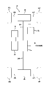
[0072] Referring to the drawings, wherein like reference numerals
illustrate corresponding
or similar elements throughout the several views, FIG. 1 is a schematic
representation of an
embodiment of a drive system 10 incorporating a center differential 12
according to an
embodiment of the present invention. The drive system 10 also includes an
engine 14 (such as
an internal combustion engine or an electric motor powertrain) that rotatably
drives a
transmission 16. The transmission 16 rotatably drives the center differential
12, which in turn
rotatably drives a front drive shaft 18F and a rear drive shaft 18R. The front
drive shaft 18F
rotatably drives a front differential 20, which in turns rotatably drives
first and second front
driven shafts 22L, 22R and front wheels 24L, 24R. The rear drive shaft 18R
rotatably drives a
rear differential 26, which in turns rotatably drives first and second rear
driven shafts 28L, 28R
and rear wheels 30L, 30R. The center differential 12 and the front
differential 20 are
operatively coupled to an electronic controller or power supply 32 and one or
more user
manipulated controls (for example, on/off switches or buttons).
Center Differential
[0073] FIGS. 2-9 provide various views of the center differential 12 of the
drive system 10
according to one embodiment. The center differential 12 includes an outer
housing or
differential housing (not shown) that is secured to a frame of a vehicle (not
shown)
incorporating the drive system 10 or to the transmission 16. The housing
rotatably carries or
supports the front drive shaft 18F and the rear drive shaft 18R via bearings
31F, 31R, which
carry spacers 33F, 33R. Generally, the housing carries an open differential
assembly 34, a bi-
directional overrunning roller clutch 36, and an electromagnet assembly 38.
The open
differential assembly 34 is driven by an input drive (not shown) of the
transmission 16, and the
open differential assembly 34 in turn drives the front drive shaft 18F and the
rear drive shaft
18R. As described in further detail below, when the electromagnet assembly 38
is not
energized, the bi-directional overrunning roller clutch 36 is disengaged and
the open
differential assembly 34 is in an unlocked configuration. In the unlocked
configuration, the
open differential assembly 34 permits relative rotation or differentiation
between the front drive
shaft 18F and the rear drive shaft 18R (for example, to facilitate turning the
vehicle). In
17
Date recue / Date received 2021-12-21
contrast, when the electromagnet assembly 38 is energized, the bi-directional
overrunning
roller clutch 36 is engaged and the open differential assembly 34 is in a
locked configuration.
In the locked configuration, the open differential assembly 34 inhibits
relative rotation between
the front drive shaft 18F and the rear drive shaft 18R (for example, to
facilitate moving the
vehicle in low-traction situations).
[0074] With continued reference to FIGS. 2-9, in the illustrated embodiment
the open
differential assembly 34 includes two input gears, more specifically a first
ring gear 40A and a
second ring gear 40B. The ring gears 40A, 40B are preferably made from steel
material. The
first ring gear 40A is driven in a first rotational direction when the vehicle
is driven in a forward
direction and the second ring gear 40B is driven in a second rotational
direction (opposite from
the first rotational direction) when the vehicle is driven in the reverse
direction. Alternatively,
the open differential assembly 34 could include a single input gear for
driving the vehicle in
both the forward and reverse directions. In the illustrated embodiment, the
first ring gear 40A
and the second ring gear 40B drive a planetary gear assembly 42. More
specifically, the first
ring gear 40A and the second ring gear 40B are fixed to a planetary carrier 44
via a plurality of
posts 46, spacers 48, and fasteners 50. The posts 46 also rotatably carry a
plurality of first
planetary gears 52A and a plurality of secondary planetary gears 52B. The
planetary gears
52A and 52B are preferably made from steel material. Each first planetary gear
52A is paired
and meshably engages one of the secondary planetary gears 52B. The first
planetary gears
52A are also disposed radially outwardly relative to and meshably engage a
first sun gear 54A.
Similarly, the second planetary gears 52B are disposed radially outwardly
relative to and
meshably engage a second sun gear 54B. The sun gears 54A and 54B are
preferably made
from steel material. The first sun gear 54A and the second sun gear 54B engage
the front drive
shaft 18F and the rear drive shaft 18R, respectively, via any conventional
means designed to
transfer torque from a gear to a shaft. In the illustrated embodiment, the sun
gears 54A and
54B includes internal splines which mate with external splines on the drive
shafts 18F and
18R. The above gearing arrangement permits the sun gears 54A and 54B and the
drive shafts
18F and 18R to rotate at different speeds relative to each other and relative
to the planetary
carrier 44. The above gearing arrangement also permits the first sun gear 54A
and the front
drive shaft 18F to rotate in the opposite direction from the second sun gear
54B and the rear
drive shaft 18R. In other embodiments, the open differential assembly 34 may
take other
18
Date recue / Date received 2021-12-21
forms. For example, the open differential assembly 34 could include a bevel
gear assembly
instead of a planetary gear assembly.
[0075] With specific reference to FIGS. 2, 4, 6, and 7, in the illustrated
embodiment the bi-
directional overrunning roller clutch 36 is partially defined by and disposed
within the planetary
carrier 44. More specifically, a portion of the planetary carrier 44 (e.g. the
rear side of the
planetary carrier 44) provides a clutch housing or recess 56 which has a
smooth inner
diameter surface 58. The clutch housing 56 is concentrically disposed around a
hub 60
including a plurality of cam surfaces 60S, also referred to as a cammed hub,
and the cam med
hub 60 engages the rear drive shaft 18R via any conventional torque transfer
means. In the
illustrated embodiment, the cammed hub 60 includes internal splines which mate
with the
external splines on the rear drive shaft 18R. As a result, the cammed hub 60
also rotates in
combination with the second sun gear 54B. The radial space between the cammed
hub 60 and
the clutch housing 56 is occupied by a roll cage 62. The roll cage 62 can be
made from any
suitable material that is sufficiently strong to withstand the applied loads,
such as hardened
anodized aluminum material, engineered polymer, or steel. The roll cage 62 has
a plurality of
equally-spaced slots 64 about its circumference. Each slot 64 holds a roller
66, and each roller
66 is preferably made from hardened steel material. One end of the roll cage
62 has a plurality
of slots or notches 68 that are engaged by an armature plate 70. The armature
plate 70 can be
engaged to the roll cage 62 in other manners. For example, while the armature
plate 70 has
been described as a separate component from the roll cage 62, it is also
contemplated that the
armature plate 70 can be attached to, formed on, or engaged with the roll cage
62 so as to
rotate in combination with the roll cage 62. Alternately, the armature plate
70 can be
permanently or removably attached to the roll cage 62, or may simply be a
surface on the roll
cage 62. The rollers 66 are biased radially inwardly toward the cam med hub 60
by one or more
springs 72, such as garter springs, which extend around the roll cage 62 and
all of the rollers
66. As described in further detail below, when the bi-directional overrunning
roller clutch 36 is
disengaged, the springs 72 bias the rollers 66 away from the clutch housing
56. As a result,
the clutch housing 56 and the cammed hub 60 are permitted to rotate at
different speeds,
which in turn permits the rear drive shaft 18R and the front drive shaft 18F
to rotate at different
speeds via the open differential assembly 34. In contrast, when the bi-
directional overrunning
roller clutch 36 is engaged, the rollers 66 wedge between the cammed hub 60
and the clutch
19
Date recue / Date received 2021-12-21
housing 56. As a result, the clutch housing 56 rotates in combination with the
cammed hub 60,
which causes the rear drive shaft 18R and the front drive shaft 18F to rotate
in combination
with each other. In other embodiments, the bi-directional overrunning roller
clutch 36 may take
other forms. For example, the hub 60 could have a uniform outer diameter and
the clutch
housing 56 could include cam surfaces for engaging the rollers 66.
[0076] With specific reference now to FIGS. 2 and 4, the electromagnet
assembly 38 is
preferably bonded or otherwise attached to the housing and is located adjacent
or in close
proximity to the armature plate 70 and the bi-directional overrunning roller
clutch 36. The
electromagnet assembly 38 includes an electromagnet housing (or pocket) 74,
preferably
annular, that carries an electromagnet or coil 76, preferably annular. The
coil 76 is configured
to receive electrical power from the controller 32 (FIG. 1; for example, upon
actuation of one of
the user manipulated controls) via an electrical harness 78. When the
electromagnet assembly
38 is energized (that is, when the coil 76 receives electrical power), the
coil 76 attracts the
armature plate 70, which causes the armature plate 70 to resist rotation. This
in turn causes
the roll cage 62 to resist rotation and drag or index the rollers 66 to a
position relative to the
cam surface 60S of the cammed hub 60 that will wedge the rollers 66 between
the cam
surface 60S and the inner surface 58 of the clutch housing 56. Once the
rollers 66 are
wedged, the cammed hub 60 and clutch housing 56 rotate in combination with
each other and
the open differential assembly 34 occupies the locked configuration as
described above.
Front Differential
[0077] Referring now to FIGS. 10-14, the front differential 20 of the drive
system 10 of one
embodiment is shown. The front differential 20 may have the same or similar
components and
features as any of the front differentials described in U.S. Patent No.
8,840,514 or U.S. Patent
No. 8,857,294. More specifically and referring first to FIGS. 10 and 11, the
front differential 20
includes a differential housing including a cover 80 removably mounted to a
differential gear
case 82. As shown, a pinion input gear 84 is rotatably disposed within the
case 82. A shaft
86 of the pinion input gear extends out from an opening in the case 82 and is
adapted to attach
to the front drive shaft 18F (FIG. 1). For example, the front drive shaft 18F
engages with a
splined end of a pinion input shaft 86. In order to facilitate rotation of the
pinion input shaft 86,
a bearing 88 is
Date Recue/Date Received 2023-03-22
preferably mounted between the shaft 86 and the case 82. An oil seal 87 is
preferably located
between the case 82 and the pinion input shaft 86. The oil seal 87 prevents
oil from escaping
out of the case 82.
[0078] The pinion input gear 84 preferably has a bevel gear 90 formed on or
attached to the
end of the shaft 86 within the differential case 82. The bevel gear 90 is
preferably made from
steel material. The bevel gear 90 engages with a ring gear 92 located within
the differential
case 82. The ring gear 92 is preferably made from steel with mating bevels. It
is contemplated
that other gearing arrangements, such as a worm gear set or helical gearset,
may be used for
engaging the pinion input shaft 86 to the ring gear 92.
[0079] The ring gear 92 is preferably formed integral with or attached to a
clutch housing
94. The clutch housing 94 includes an internal diameter with a contour or cam
surface 96. A
bushing 98 is mounted between the clutch housing 94 and the differential case
82 for
permitting the clutch housing 94 to freely rotate within the differential case
82. The bushing
98 is preferably a self-lubricating bushing, such as a DU bushing. A roll cage
assembly 100 is
located within the clutch housing 94 and includes a roll cage 102 with a
plurality of rollers 104
rotatably disposed within slots 106 in the cage 102. More specifically, the
roll cage 102
preferably includes two independent sets of rollers 104 disposed within two
sets of slots 106
formed in the roll cage 102 around its circumference. The roll cage 102 can be
made from any
suitable material that is sufficiently strong to withstand the applied loads,
such as hardened
anodized aluminum material or steel. Alternatively, the roll cage 102 can be
made from plastic
or composite material. The rollers 104 are preferably made from hardened steel
material. The
roll cage assembly 100 includes a plurality of spring elements or clips (not
shown) for
positioning the rollers 104 in the slots 106. A variety of springs may be
used. In some
embodiments, each spring clip is preferably substantially H-shaped with two
independent
springs that are attached to or formed on opposite sides of a bridge. The
bridge separates
each spring into two opposed arms. The arms are preferably curved or arcuate
in shape such
that the combination of the arms is concave, similar to the shape of a leaf
spring. However, the
arms may also be linear such that they combine with the bridge to form a Y
shape. The bridge
acts as a yoke to support the arms permitting them to bend independently from
one another,
as well as from the opposite spring. Each slot 106 includes a spring from two
adjacent spring
clips, thus biasing the roller substantially into the center of the slot. The
springs account for
21
Date recue / Date received 2021-12-21
tolerances in the manufacturing of the various components so that the rollers
all engage at the
same time. Other spring mechanisms can be used in the present invention. U.S.
Pat. Nos.
6,629,590, 6,622,837 and 6,722,484, disclose suitable spring arrangements and
roll cage
assemblies.
[0080] Each set of rollers 104 is located adjacent to the inner cam surface
96 of the clutch
housing 94. In one configuration, of the contour of the cam surface 96
includes a plurality of
peaks and valleys. When the roll cage 102 is located within the clutch housing
94 and the
clutch is not activated, the rollers 104 are located within the valleys with
the cam surface 96
tapering toward the cage on either side of the roller 104. The cam surface 96
and rollers
104 provide the front differential 20 capabilities as described in detail in
U.S. Pat. Nos.
6,629,590, 6,622,837 and 6,722,484. Cam surfaces and roll cages in overrunning
clutches are
well known in the art. Hence, a detailed discussion of these features is not
needed.
[0081] With continued reference to FIGS. 10 and 11, there are two hubs
108A, 108B, which
include a portion located radially inward of the roll cage 102. Each hub 108A,
108B is adjacent
to one of the sets of rollers 104 such that the outer surface of a portion of
each hub contacts a
set of rollers 104. As is well understood in the art, the contact between the
rollers 104, the
clutch housing 94 and the hubs 108A, 108B transfer rotation between the clutch
housing and
the axles. A bushing 110 is preferably located between the inner ends of the
two hubs 108A,
108B.
[0082] The hubs 108A, 108B engage with the first and second front driven
shafts 22L, 22R
(FIG. 1), respectively, via any conventional means designed to transfer torque
from the hub to
the shaft. In the illustrated embodiment, each hub 108A, 108B includes
internal splines which
mate with external splines on a portion of the front driven shafts 22L, 22R.
It is contemplated
that the hubs 108A, 108B and the front driven shafts 22L, 22R could be formed
as integral
units if desired. The internal splines on the hubs 108A, 108B are accessible
through openings
formed in the cover 80 and gear case 82. Roller bearings 112A, 112B are
mounted between a
portion of each hub 108A, 108B and the corresponding cover 80 or case 82. The
roller
bearings 112A, 112B support the hubs 108A, 108B while permitting the hubs
108A, 108B to
rotate with respect to the cover 80 and case 82, respectively. A spacer 113 is
positioned
adjacent the hub 108B, and the spacer 113 positions the roll cage 102. Oil
seals 114A, 114B
22
Date Recue/Date Received 2023-03-22
are preferably incorporated into the cover 80 and case 82 around the hubs
108A, 108B,
respectively, to provide fluid tight seals.
[0083] As discussed briefly above, the engagement of the rollers 104 with
the clutch
housing 94 and hubs 108A, 108B permits the transfer of torque from the front
drive shaft
18F to the front driven shafts 22L, 22R. In order to activate the overrunning
clutch and thereby
make the vehicle capable of engaging in four-wheel drive and engine braking,
the front
differential 20 preferably incorporates an electromagnet assembly. More
specifically, the front
differential 20 includes two or more roll cage adjustment devices or indexing
devices which are
electrically connected to an electronic control system. Each adjustment device
preferably
includes an electromagnetic coil assembly. The first indexing device (e.g.,
the electronic or
electromagnetic drive activation device or electromagnetic drive coil
assembly) is configured,
when activated, to cause the roll cage to index into an active drive state
(i.e., four-wheel drive
capability) where the rolls are positioned to cause the front drive shaft 18F
be coupled to the
front driven shafts 22L, 22R when four-wheel drive capability is needed.
[0084] The second indexing device (e.g., the electromagnetic backdrive
activation device or
electromagnetic backdrive coil assembly) is configured, when activated, to
cause the roll cage
to index into an active backdrive state (i.e., engine breaking capability)
where the rolls are
positioned to cause the front driven shafts 22L, 22R to be coupled to the
front drive shaft
18F for providing torque transfer from the front driven shafts 22L, 22R to the
front drive shaft
18F during an engine braking condition. The second indexing device may be
activated when
the vehicle is decelerating or on a downhill.
[0085] With continued reference to FIGS. 10 and 11 and additional reference
to FIG. 12, in
the illustrated embodiment, each electromagnetic indexing device includes a
coil assembly that
includes a coil in an annular steel coil pocket or housing and an armature
plate which control
retarding or indexing of the roll cage 102 with respect to the clutch housing
94. The first
indexing device includes a drive coil assembly 116 that is preferably attached
to the cover 80
at a location radially outward from the hub 108A. The drive coil assembly 116
is preferably
annular in shape with a central axis coincident with the axis of rotation of
the roll cage 102. The
drive coil assembly 116 is preferably a bobbin wound coil which includes a
plastic base about
which the coil is wound. Suitable coils for use in the present invention are
well known to those
23
Date recue / Date received 2021-12-21
skilled in the electric clutch art. The drive coil assembly 116 is preferably
bonded or otherwise
attached to the cover 80.
[0086] A first armature plate 118 is located between the drive coil
assembly 116 and the roll
cage 102. The armature plate 118 is preferably annular in shape and is free to
rotate with
respect to the drive coil assembly 116 when the coil is not energized. The
armature plate 118
includes at least one and, more preferably a plurality of tangs or fingers 120
which protrude
from the armature plate 118 toward the roll cage 102. The tangs 120 engage
with slots or
notches formed in or on an end face of the roll cage 102. The armature plate
118 is engaged
with the roll cage 102 when the tangs 120 are engaged with the slots. Hence,
when the drive
coil assembly 116 is not energized, the armature plate 118 rotates with the
roll cage 102
relative to the clutch housing 94. The armature plate 118 is preferably made
from steel
material. While a separate armature plate 118 has been described, it is also
contemplated that
armature plate can be attached to, formed on, or engaged with the roll cage
102 so as to rotate
in combination with the roll cage 102. Alternately, the armature plate 118 can
be permanently
or removably attached to the roll cage 102, or may simply be a surface on the
roll cage 102.
[0087] When the drive coil assembly 116 is energized, an electromagnetic
field is
generated between the drive coil assembly 116 and the armature plate 118
attracting the
armature plate 118 to the drive coil assembly 116, thus causing it to drag.
Because the
armature plate 118 is engaged with the roll cage 102 by the tangs 120, the
dragging of the
armature plate 118 causes the roll cage 102 to also drag or retard. In an
alternate embodiment
(not shown), instead of tangs 120 on the armature plate 118 engaging with
slots, the roll cage
102 includes protrusions that engage with slots in the armature plate 118. The
drive coil
assembly 116 is connected to the controller 32 (FIG. 1) for controlling
energizing of the coils
(for example, upon actuation of one of the user manipulated controls).
[0088] The second indexing device includes a backdrive coil assembly 122
that is
preferably attached to the cover 80 at a location radially outward from the
hub 108A but inward
from the drive coil assembly 116. The backdrive coil assembly 122 is
preferably similar to the
drive coil assembly 116 and is annular in shape with a central axis coincident
with the axis of
rotation of the roll cage 102. The backdrive coil assembly 122 is preferably
bonded or
otherwise attached to the cover 80.
24
Date recue / Date received 2021-12-21
[0089] A second armature plate 124 is located between the backdrive coil
assembly 122
and the roll cage 102. The second armature plate 124 is preferably annular in
shape and is
free to rotate with respect to the backdrive coil assembly 122 when the coil
is not energized.
The second armature plate 124 includes at least one and, more preferably a
plurality of tangs
or fingers 126 which protrude from the second armature plate 124 toward the
roll cage 102.
The tangs 126 engage with slots formed in or on an end of the roll cage 102.
The second
armature plate 124 is engaged with the roll cage 102 when the tangs 126 are
engaged with the
slots. Hence, when the backdrive coil assembly 122 is not energized, the
second armature
plate 124 rotates with the roll cage 102 relative to the clutch housing 94.
The second armature
plate 124 is preferably made from steel material. As with the first armature
plate 118, the
second armature plate 124 can be engaged to the roll cage 102 in other
manners. For
example, while the second armature plate 124 has been described above as a
separate
component from the roll cage 102, it is also contemplated that the second
armature plate 124
can be attached to, formed on, or engaged with the roll cage 102 so as to
rotate in combination
with the roll cage 102. Alternately, the second armature plate 124 can be
permanently or
removably attached to the roll cage 102, or may simply be a surface on the
roll cage 102. It is
also contemplated that a single armature plate can be used in the front
differential 20 with two
independently controlled coil assemblies mounted in a common cover or housing.
It is also
contemplated that two armature plates could be interlocking with drive
feature(s) but only one
of the armature plates is interacting with the roll cage 102.
[0090] A hub plate 128 is positioned between the backdrive coil assembly
122 and the
second armature plate 124. The hub plate 128 is engaged with the hub 108A.
Specifically, the
hub plate 128 is annular in shape and includes, in one preferred embodiment,
teeth 130
around an inner diameter that engage with splines 132 formed on an outer
surface of the hub
108A. Thus, the hub plate 128 is configured to rotate in combination with the
hub 108k Other
mechanisms can be used to engage the hub plate 128 to the hub 108k An upper
portion of
the hub plate 128 is located adjacent to the backdrive coil assembly 122 and
the second
armature plate 124.
[0091] When the backdrive coil assembly 122 is energized, an
electromagnetic field is
generated between the backdrive coil assembly 122, the hub plate 128 and the
second
armature plate 124 attracting the hub plate 128 and second armature plate 124
to the
Date recue / Date received 2021-12-21
backdrive coil assembly 122. Since the hub plate 128 is coupled to the hub
108A, activation of
the backdrive coil assembly 122 magnetically holds the second armature plate
124 to the hub
108A thus causing it to want to rotate with the hub 108A. Since the second
armature plate 124
is engaged with the roll cage 102 by the tangs 126, the magnetic engagement of
second
armature plate 124 causes the roll cage 102 to advance relative to the clutch
housing 94 as
the hub 108A rotates. The backdrive coil assembly 122 is also connected to the
electronic
controller 32 for controlling energizing of the coils (for example, upon
actuation of one of the
user manipulated controls).
[0092] While the first and second indexing systems are described above as
including coil
assemblies, it is also contemplated that other electronically controlled
assemblies can be used.
For example, an electrically controlled solenoid could be used to cause the
indexing. In this
embodiment, the solenoid would be activated by the electronic control system
so as to cause a
plunger to engage the armature plate, hub plate, and/or a surface on the roll
cage to produce
the necessary frictional contact for dragging the roll cage into its indexed
position. Other
systems, such as hydraulic and pneumatic actuators can be used in place of the
coils and
similarly controlled by the electronic control system. A person skilled in the
art, in light of the
teachings provided in this description, would be readily capable of
implementing such systems
into the clutch system shown.
[0093] The indexing systems above are configured to move the roll cage 102
in a
prescribed direction relative to the clutch housing when a certain state of
operation is desired
(four-wheel drive or engine braking). When those states are no longer desired,
the system
includes a spring assembly for biasing the roll cage 102 back to its neutral
position. Referring
now to FIGS. 12-14, the spring assembly may be a torsion spring assembly 134.
The torsion
spring assembly 134 includes a spring retainer adapter 136 which, as will be
discussed below,
provides a connection between a torsion spring 138 and the first armature
plate 118. However,
as will become apparent, the adapter 136 could alternately be connected to the
second
armature plate 124. The adapter 136 is an annular ring that is disposed about
an outer surface
of the clutch housing 94. One side of the adapter 136 is located adjacent to a
portion of the
first armature plate 118. In one embodiment the adapter 136 has at least one
and more
preferably a plurality of protruding lugs or tabs 140 that extend out of the
side of the adapter
136 facing the first armature plate 118. The lugs 140 mate with notches 142
formed in the first
26
Date recue / Date received 2021-12-21
armature plate 118. The mating of the adapter 136 with the armature plate 118
provides a
connection between the adapter 136 and the roll cage 102 (which is engaged
with the
armature plate through the tabs 120). The adapter 136 includes an adapter pin
144 (FIG. 14)
that protrudes out of the side of the adapter 136 opposite from the armature
plate 118.
[0094] The torsion spring 138 is generally circular in shape with its ends
overlapping. The
spring 138 is also disposed about the outer surface of the clutch housing 94
and adjacent to
the adapter 136. The torsion spring 138 is designed to bias the roll cage 102
to its neutral
position (with the rolls centered in the cam surface 96). The overlapping ends
of the torsion
spring 138 include arms 146A, 146B that extend at a generally right angles to
where they
extend from the spring 138. The ends of the torsion spring overlap such that
the arms 146A,
146B on the torsion spring 138 extend past one another defining a gap 148. A
clutch pin 150
extends outward from the clutch housing 94 and is captured in the gap 148 with
the arms
146A, 146B on either side of the clutch pin 150. The arms 146A, 146B are also
on either side
of the adapter pin 144 which is located adjacent to the clutch pin 150. Thus,
the adapter 136
acts to retain the torsion spring 138 on the clutch housing 94.
[0095] When the first indexing device is energized it hinders the rotation
of the armature
plate 118, thus hindering the roll cage 102 and adapter 136. This causes the
adapter pin 144
to move one of the spring arms 146A away from the other spring arm 146B (which
is held
stationary by the clutch pin 150). This movement causes the torsion spring 138
to deflect at
which point the spring force of the torsion spring 138 acts against the
adapter pin 144 to bias it
back toward the clutch pin 150 and the neutral position of the roll cage 102.
[0096] The incorporation of a torsion spring 138 provides much tighter
tolerance and
provides a reliable mechanism for returning the roll cage 102 to its neutral
position, preventing
unwanted wedging of the rolls between the cam surface 96 and the hub. The
torsion spring
138 also prevents premature engagement that could potentially occur in some
designs. Also,
the use of a torsion spring 138 reduces the need for the roll springs to be
designed to bias the
roll cage 102 into a neutral position. Thus, the operational life of the roll
springs is increased.
Other types of spring assemblies can be used in the front differential 20. For
example, one or
more springs could be mounted between the roll cage 102 and the clutch housing
94 (one end
of the spring on the housing 94 the other on the roll cage 102) for biasing
the roll cage 102 into
27
Date recue / Date received 2021-12-21
its neutral position from an indexed position. Two springs can be used, each
biasing the roll
cage 102 in the opposition position. In this embodiment a spring adapter is
not needed. If a
spring adapter is used, the springs could be mounted between the adapter 136
and the roll
cage 102.
Rear Differential
[0097] Referring now to FIGS. 15-18, the rear differential 26 of the drive
system 10 of one
embodiment is shown. The rear differential 26 may have the same or similar
components and
features as any of the rear differentials described in U.S. Patent No.
8,919,513 or 9,022,195.
More specifically and referring first to FIGS. 15 and 16, the rear
differential 26 includes a
housing 152 and a flange 154 affixed to the housing 152. The flange 154 is
adapted to receive
or engage with an input gear or sprocket that is engaged with the rear drive
shaft 18R (FIG. 1)
for imparting rotational movement to the flange 154 and thus to the housing
152. The input
gear may be attached to the flange 154 by any mechanical means known in the
art, or may be
formed as an integral part of the flange 154 or housing 152. When the rear
drive shaft 18R is
engaged with the input gear, the flange 154 rotates, which in turn rotates the
housing 152.
The rear differential 26 is mounted in an outer housing (not shown), and
bearings 176A and
176B support the rear differential 26 in the outer housing.
[0098] As shown in FIG. 17, the housing 152 includes a substantially
cylindrical inner
surface 156. The inner surface 156 includes a plurality of an inner cam
surfaces (not shown)
including forward and reverse cam surfaces. Depending on the desired direction
of rotation of
the housing 152, either cam surface may be interchangeably considered as a
forward or a
reverse cam surface.
[0099] With continued reference to FIG. 17, a pair of hubs 158A, 158B is
located within the
housing 152. The hubs 158A, 158B are substantially coaxially aligned with each
other within
the housing 152, and are each adapted to rotate about their common axis within
the housing
152. The first hub 158A is adapted to engage an end of the first rear driven
shaft 28L (FIG. 1)
and the second hub 158B is adapted to engage an end of the second rear driven
shaft 28R
(FIG. 1). Each hub 158A, 158B has a substantially cylindrical outer surface
160 having a
diameter smaller than the diameter of the inner surface 156 of the housing
152, so that an
28
Date Recue/Date Received 2023-03-22
annular space is formed between the outer surface 160 of the hubs 158A, 158B
and the inner
surface 156 of the housing 152. Each hub 158A, 158B preferably has an internal
bore 162 into
which a portion of the corresponding driven shaft is received. In the depicted
embodiment, the
internal bores 162 include splines to allow the shafts to move axially inward
and outward with
respect to the hubs 158A, 158B while ensuring that each shaft will rotate in
combination with
its respective hub 158A, 158B. In other embodiments, other mechanical
connections between
each shaft and its respective hub 158A, 158B may be used to ensure rotational
coupling. It is
further contemplated that the hubs 158A, 158B may be formed integrally with
the primary drive
shafts.
[0100] A pair of roller assemblies 164A, 164B is located within the housing
152, with a
portion of each roller assembly 164A, 164B being situated in the annular space
between the
outer surface 160 of one of the hubs 158A, 158B and the inner surface 156 of
the housing 152.
As shown in FIG. 17, the roller assemblies 164A, 164B include roll cages 166A,
166B,
respectively, that are formed in substantially cylindrical shapes. The roll
cages 166A, 166B
correspond to the hubs 158A, 158B, respectively, and have sets of slots (not
shown) spaced
around their circumferences. The slots are adapted to receive cylindrical
rollers 168A, 168B.
The slots of the first roll cage 166A position a plurality of rollers 168A in
the annular space
between the first hub 158A and the inner cam surface 156 of the housing 152,
and the slots of
the second roll cage 166B position a plurality of rollers 168B in the annular
space between the
second hub 158B and the inner cam surface 156 of the housing 152. In one
embodiment, each
set of rollers 168A, 168B has ten rollers, it being understood that any number
of rollers greater
than or equal to three may be used. As shown, each roller 168A, 168B is
substantially
cylindrical, but rollers of other shapes may be used, including but not
limited to substantially
spherical rollers.
[0101] The rollers 168A, 168B are adapted to be wedgingly engaged between the
hubs
158A, 158B, respectively, and the inner cam surface 156 of the housing 152
when the hubs
158A, 158B and the housing 152 are rotated with respect to the other. In
particular, when the
housing 152 is rotationally driven at a speed faster than the hubs 158A, 158B
are rotating, the
rollers 168 are designed to wedgingly engage between the forward cam surfaces
in the
housing and the outer surfaces 160 of the hubs 158A, 158B, causing the hubs
158A, 158B to
rotate with the housing 152. Similarly, when both hubs 158A, 158B are rotating
faster than the
29
Date recue / Date received 2021-12-21
housing 152, such as during a descent or deceleration, the hubs 158A, 158B
cause the rollers
168A, 168B to wedge between the reverse cam surfaces and the outer surfaces
160 of the
hubs 158A, 158B. The reverse cam surface engagement enables an engine braking
or back
driving effect, when available, whereby the reduced speed of the input gear
slows or brakes
the drive axles.
[0102] Providing two separate roller assemblies 164A, 164B, each having a
set of rollers
168A, 168B associated with one of the hubs 158A, 158B, allows overrunning of
one hub 158A,
158B while maintaining positive driving engagement of the other hub 158A,
158B. For
example, in a wheeled vehicle in which the hubs 158A, 158B drive wheels on
opposite sides of
the vehicle, when the vehicle travels around a curve, the wheel on the inside
of the curve has a
shorter distance to travel, and thus travels at a slower speed, than the wheel
on the outside of
the curve. Consequently, when the housing 152 is being rotationally driven
while the vehicle is
in a curve, one hub 158A, 158B, for example hub 158A, associated with the
inside wheel will
continue to be driven, with its rollers 168A engaged between the outer surface
160 of the hub
158A and the forward cam surfaces of the inner surface 156 of the housing 152,
while the
other hub 158B, for example hub 158B, associated with the outside wheel will
be allowed to
overrun, turning faster than the housing 152, such that its rollers 168b
disengage from their
wedging between the inner cam surface 156 and the outer surface 160 of the hub
158B, thus
allowing the hub 158B to freely rotate as it is driven by the outside wheel.
When the vehicle
returns to a straight path and the speed of the disengaged hub 158B slows down
to equal the
speed of the housing 152, the rollers 168B surrounding the hub 158B re-engage
(wedge)
between the forward cam surfaces and hub 158A, 158B so that the hub 158B is
once again
driven to rotate at the same speed as the housing 152.
[0103] However, because the rear differential 26 uses a split roll cage, if
the two roller
assemblies 164A, 164B were completely decoupled, there is the potential that
the rollers 168B
associated with the overrunning hub 158B could go into reverse engagement with
the reverse
cam surfaces of the inner surface 156 of the housing 152, thereby causing the
vehicle to act as
if it has a solid axle (i.e., one axle being driven by the housing 152, while
the other axle tries to
drive the housing 152). To overcome potential reverse engagement of an
overrunning hub, the
rear differential 26 includes a roll cage coupler 170 positioned between the
two roller
assemblies 164A, 164B. The coupler 170 includes a hub 172 with a plurality of
teeth 173
Date recue / Date received 2021-12-21
extending radially outward from the hub 172. The number of teeth preferably
matches the
number of slots and the number of rollers 168A, 168B in each roll cage 166A,
166B. The teeth
of the coupler 170 preferably fit into the slots in each roll cage 166A, 166B.
The width of the
portion of each tooth within a slot is slightly less than the width of the
slot of the roll cages
166A, 166B such that a gap is present. This gap is designed to permit the roll
cages 166A,
166B to shift or index so that the rollers 168A, 168B are positioned to engage
with the cam
surface, but the gap is not large enough to permit the other roll cage 166A,
166B to index in
the opposite direction. Accordingly, by using an intermittent coupler 170, the
split cage design
prevents the issue of one set of rollers engaging the forward cam surface to
drive one axle and
the other set of rollers engaging the reverse cam surface to be driven by the
other axle.
[0104] Rotationally coupling together two separate roll cages 166A, 166B
with an
intermittent coupler 170 allows each roll cage 166A, 166B to move axially with
respect to its
associated hub 158A, 158B, which enables a compact and simple friction disk
mechanism to
index each roll cage 166A, 166B relative to its associated hub 158A, 158B. The
intermittent
coupler also allows for a large torque difference from one axle to the other,
and also allows for
larger manufacturing tolerances in the clutch cam profile and hub diameters.
The intermittent
coupler also provides a method for retaining the roll assemblies in axial
position so to prevent
one set from contacting the other.
[0105] End caps 174A, 174B are attached to each end of the housing 152 so
as to rotate
with the housing 152. In some embodiments and as illustrated, the end cap 174A
is formed
together with the flange 154. The end caps 174A, 174B are coupled to bearings
176A, 176B,
respectively. To assist in indexing the roller assemblies 164A, 164B to their
corresponding
hubs 158A, 158B, the end caps 174A, 174B are associated with friction disk
mechanisms
178A, 178B, respectively. The friction disk mechanisms 178A, 178B create a
frictional
engagement with the roller assemblies 164A, 164B and the hubs 158A, 158B,
respectively, so
that the roll cages 166A, 1666 rotate with the hubs 158A, 158B when both hubs
158A, 158B
are rotating. In combination, the friction disk mechanisms 178A, 178B and the
roll cage coupler
170 make up an indexing assembly.
[0106] Each friction disk mechanism 178A, 178B may include a friction plate
or disk
180 that is attached to, formed on, or engaged with the roll cage 166A, 166B
so as to rotate in
31
Date recue / Date received 2021-12-21
combination with the roll cage 166A, 166B. The friction plate 180 can be
permanently or
removably attached to the roll cage 166A, 166B, or may simply be a surface on
the roll cage
166A, 166B. In one embodiment, the friction plate 180 is a substantially
planar annular ring
with radially extending tabs or teeth that are sized to extend into the slots
on the roll cage
166A, 166B when the friction plate 180 is placed on the roll cage 166A, 166B
and adjacent to
an inside end surface of the roll cage 166A, 166B. The friction plate 180 is
configured to
provide a frictional engagement with a portion of the hubs 158A, 158B. More
specifically, in
one embodiment, the hubs 158A, 158B include a contact surface 181, which may
be integral
with, formed on, or attached to the hub, preferably on an axial end surface of
the hub so as to
be adjacent to a portion of the friction plate 180. The portions of the
friction plate 180 and the
contact surface 181 that contact one another preferably have a sufficient
coefficient of friction
to create frictional contact for transferring torque between the two.
[0107] Springs 182 are compressed between bushings 184 and end surfaces of
the roll
cages 166A, 166B. In the depicted embodiment, the springs 182 are wave
springs. The
springs 182 bias the roll cages 166A, 166B, and thus the friction plate 180,
into the contact
surfaces 181 of the hubs 158A, 158B. As such, the springs 182 cause the roll
cages 166A,
166B to move axially with respect to the hubs 158A, 158B, respectively,
thereby urging the
friction plate 180 into frictional engagement with the hubs 158A, 158B.
System Operation
[0108] The drive system 10 is capable of providing power to at least one of
the wheels 24L,
24R, 30L, and 30R in various situations. For example and referring to FIG. 19,
when traction is
present at all four wheels 24L, 24R, 30L, and 30R, the system 10 provides
power to all four
wheels 24L, 24R, 30L, and 30R and the center differential 12 may be in either
the unlocked
configuration or the locked configuration. As another example and referring to
FIG. 20, when
traction is present at three wheels (illustratively, the front wheels 24L, 24R
and the rear right
wheel 30R) and absent at one wheel (illustratively, the rear left wheel 30L),
the system 10
provides power to the three wheels (illustratively, the front wheels 24L, 24R
and the rear right
wheel 30R) and the center differential 12 may be in the unlocked or locked
configuration.
Referring to FIG. 21, when traction is present at two wheels on a common axle
(illustratively,
the front wheels 24L, 24R) and absent at the other two wheels (illustratively,
the rear wheels
32
Date recue / Date received 2021-12-21
30L, 30R) and if the center differential 12 is in the unlocked configuration,
the system 10
provides power to the other two wheels (illustratively, the rear wheels 30L
and 30R), which
causes the other two wheels to slip and spin, which in turn causes no movement
of the first
two wheels (illustratively, the front wheels 24L and 24R). However, and
referring to FIG. 22,
when traction is present at two wheels on a common axle (illustratively, the
front wheels 24L,
24R) and absent at the other two wheels (illustratively, the rear wheels 30L,
30R) and if the
center differential 12 is in the locked configuration, the system 10 provides
power to all wheels.
As another example and referring to FIG. 23, when traction is present at one
wheel
(illustratively, the front right wheel 24R) and absent at three wheels
(illustratively, the front left
wheel 24L and the rear wheels 30L, 30R) and the center differential 12 is in
the locked
configuration, the system 10 provides power to all of the wheels, but that
power is only usable
to propel the vehicle by the wheel with traction (illustratively, the front
right wheel 24R)._The
drive system 10 may be reconfigured from the unlocked configuration to the
locked
configuration or vice versa upon actuation of one or more user manipulated
controls (for
example, on/off switches or buttons).
[0109] The drive system 10 advantageously provides one or more various
benefits
compared to other systems. For example, the drive system 10 does not require
computer
controls, sensors, friction plate clutches, or associated electric motor
actuators or hydraulics.
As another example, the drive system 10 more efficiently transfers power to
drive a vehicle; in
contrast, in other systems efficiency losses occur when power is directed to
the wheel without
traction and heat losses occur upon clutch plate actuation. As another
example, the drive
system 10 does not require wear or heat mitigation for friction plate clutch
material. As yet
another example, the drive system 10 requires less time to redistribute power
to the wheels; in
contrast, other systems require more time to redistribute power due to the
need to actuate
plate clutch packs via hydraulics or electric actuators.
[0110] Drive systems according to embodiments of the present invention may
be modified
from the systems described above. For example and referring now to FIGS. 24
and 25, a
center differential 210, which may be used in a drive system instead of the
center differential
12, illustrated. The center differential 210 is similar to the center
differential 12, and similar
components are illustrated with the same reference numbers. Generally, the
center differential
210 includes an open differential assembly 34 and a bi-directional overrunning
roller clutch 36
33
Date recue / Date received 2021-12-21
as described above. The center differential 210 also includes an electromagnet
assembly 212
for engaging the bi-directional overrunning roller clutch 36 and thereby
locking the open
differential assembly 34. The electromagnet assembly 212 includes an
electromagnet housing
74 that carries an electromagnet or coil 76 as described above. When the
electromagnet
assembly 212 is energized, the coil 76 attracts a second armature plate 214,
which transfers
magnetic flux to the first armature plate 70. The second armature plate 214
also engages the
second ring gear 40B (for example, by including protrusions 216 received in
recesses 218 on
the second ring gear 40B. This results in a connection from the second ring
gear 40B through
the second armature plate 214 and the first armature plate 70 to the roll cage
62, causing it to
resist rotation. In this configuration if the cammed hub 60 is rotating faster
than either ring gear
40A and 40B while the coil 76 is energized, the cammed hub 60 and the second
armature
plate 214 will drag the first armature plate 70, causing the roll cage 62 to
rotate relative to the
hub 60 and index into an engaged position where the rolls 66 wedge between the
cams on the
hub 60 and the inner bore of the clutch housing 44. If the second ring gear
40B and therefore
the clutch housing 44 is rotating faster than the cammed hub 60 while the coil
76 is energized,
the second armature plate 214 will be turning faster than the first armature
plate 70. The
magnetic force and friction acting between the two plates 70, 214 will cause
the second
armature plate 214 to rotate the first armature plate 70, which rotates the
roll cage 62 and
changes the relative position of the rolls 66 relative to the cams on the hub
60, thereby locking
the rolls 66 between the cams and inner surface of the clutch housing 44 so as
to transmit
torque between the ring gear 40B and the drive shafts 18F, 18R.
[0111] Although the invention has been described and illustrated with
respect to the
exemplary embodiments thereof, it should be understood by those skilled in the
art that the
foregoing and various other changes, omissions and additions may be made
therein and
thereto, without parting from the spirit and scope of the present invention.
34
Date recue / Date received 2021-12-21